-
Start of pcb wrapup
11/12/2015 at 08:42 • 0 commentsI'm back on the project, slight distraction as I finished the digital wall clock I started 19 years ago.
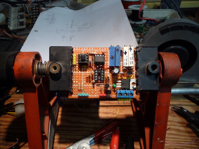
I have been busy gathering up the schematics and re-glueing and testing them. things have come togethor enough for me to start building one of the 3 pcbs that will make the new regulator system.
![]()
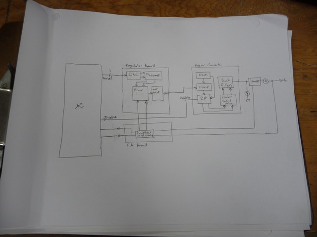
The system will be broken into 3 baords,
![]()
A regulator board, a power converter, and a feedback conditioner.
Schematics are as follows, some testing still needs to be done. Thanks for all the people who have helped sofar and all the peoples work that I'v stolen to get this far.
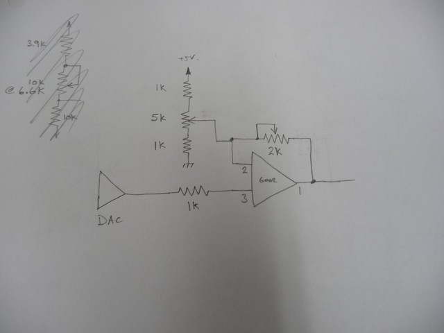
The DAC outputs 1.25-3.75V, so this expands it to 0-5V which I was trying to avoid, but made more of a mess. MCP6002 amp, 5V supply.
![]()
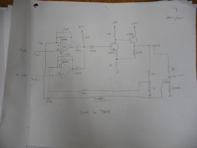
Error amplifer, this will take the voltage and current feedback, and work out what the drive signal needs to be to the power amp. The two dividers on the right were just for testing functionality.
![]()
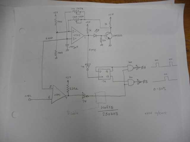
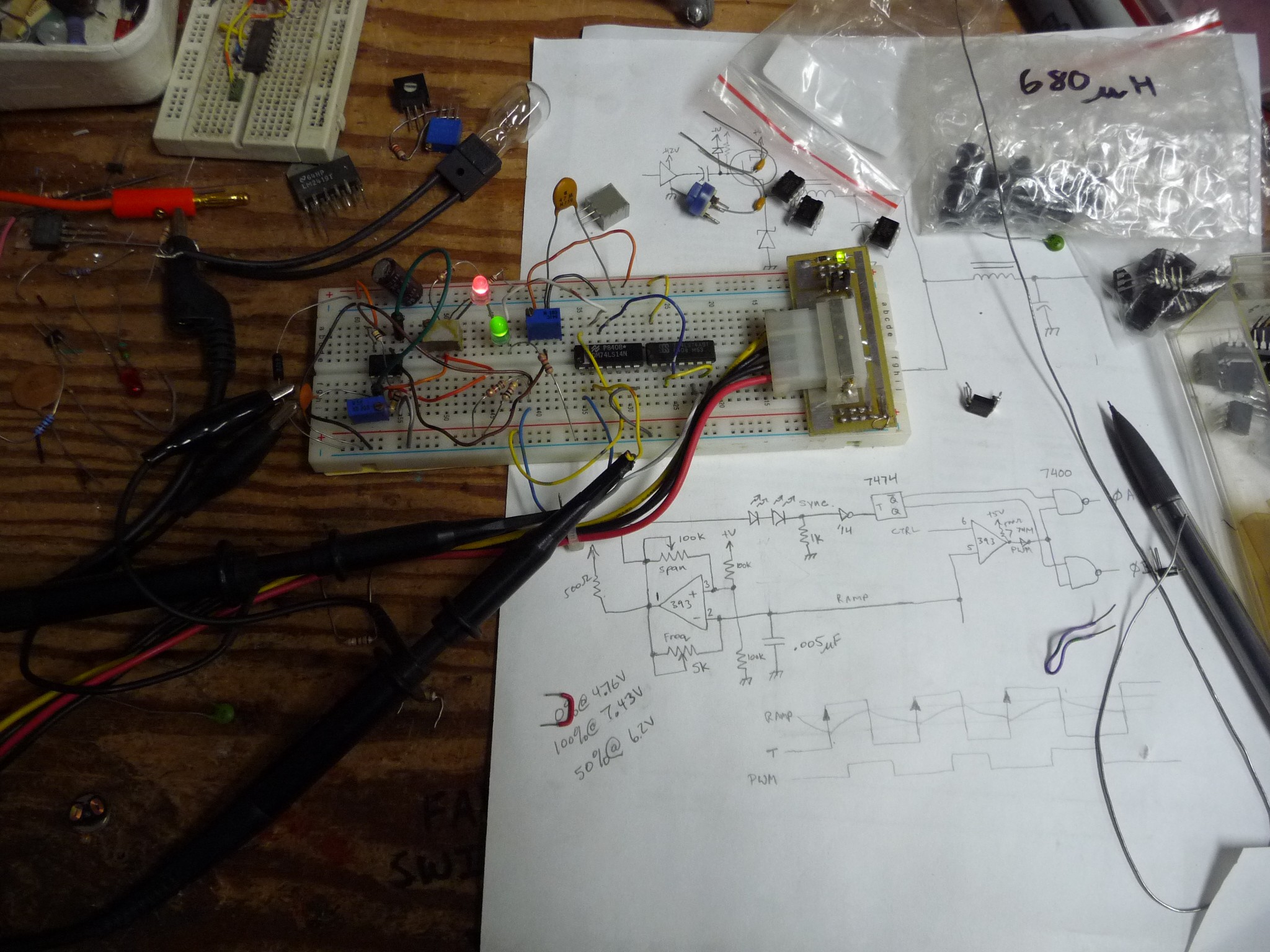
PWM genorator, 250Khz, 2 phase. Splitting the pwm into two phases that max 50% duty means I can use a capacitor for level shifting. I'm going to insert a gate for the microprocessor to disable the outputs till everything is ready during startup.
![]()
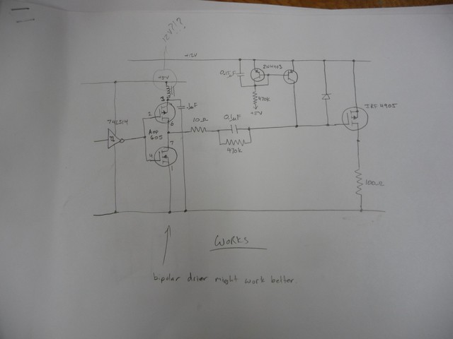
Fet driver, today I was looking at changing this to drive the fets at 12V, it would reduce the on resistance loss from 1W to 0.5W, but, it makes life really hard, so I'm going to stay with the 5V drive.
250Khz is really hard to work with, you have to pick parts carefully to get a fast enough responce.
Note the 0.1uF level shifting capacitor.
![]()
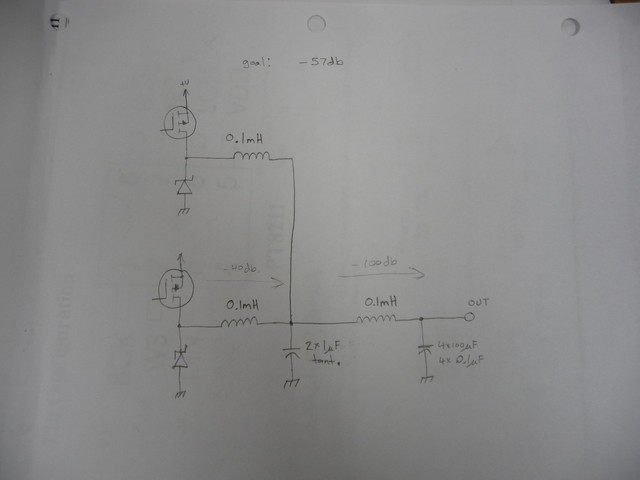
Output filter, from what I can work out, I need -57db this gives me -140db in 2 stages, the idea is that the first stage components wont be stressed (large 1uF caps) and the reduced ripple to the second stage will lower the ESR evils that usually cause those caps to fail.
![]()
Thats all, I'm gonna be testing and soldering for a while.
Why does it have to be so hard to make a variable current regulated, variable voltage supply that can go down to 0V and take up to 5A?
-
Regulator wrapup starts
10/25/2015 at 16:00 • 0 commentsI'm just back from my training course. I have started designing the power section from the DAC end. the first board will go from the DACs to an analog control voltage for the power stage. The board after that will be a pwm amplifer (30V, 5A, 2 phase, 250Khz, gain of about 6)
Last night I piggybacked some DACs onto some DIP8s that seem to have had a hole drilled thru them right where their die was. having the DACs as DIP8s will make my life easier for now.
-
Little time, little things
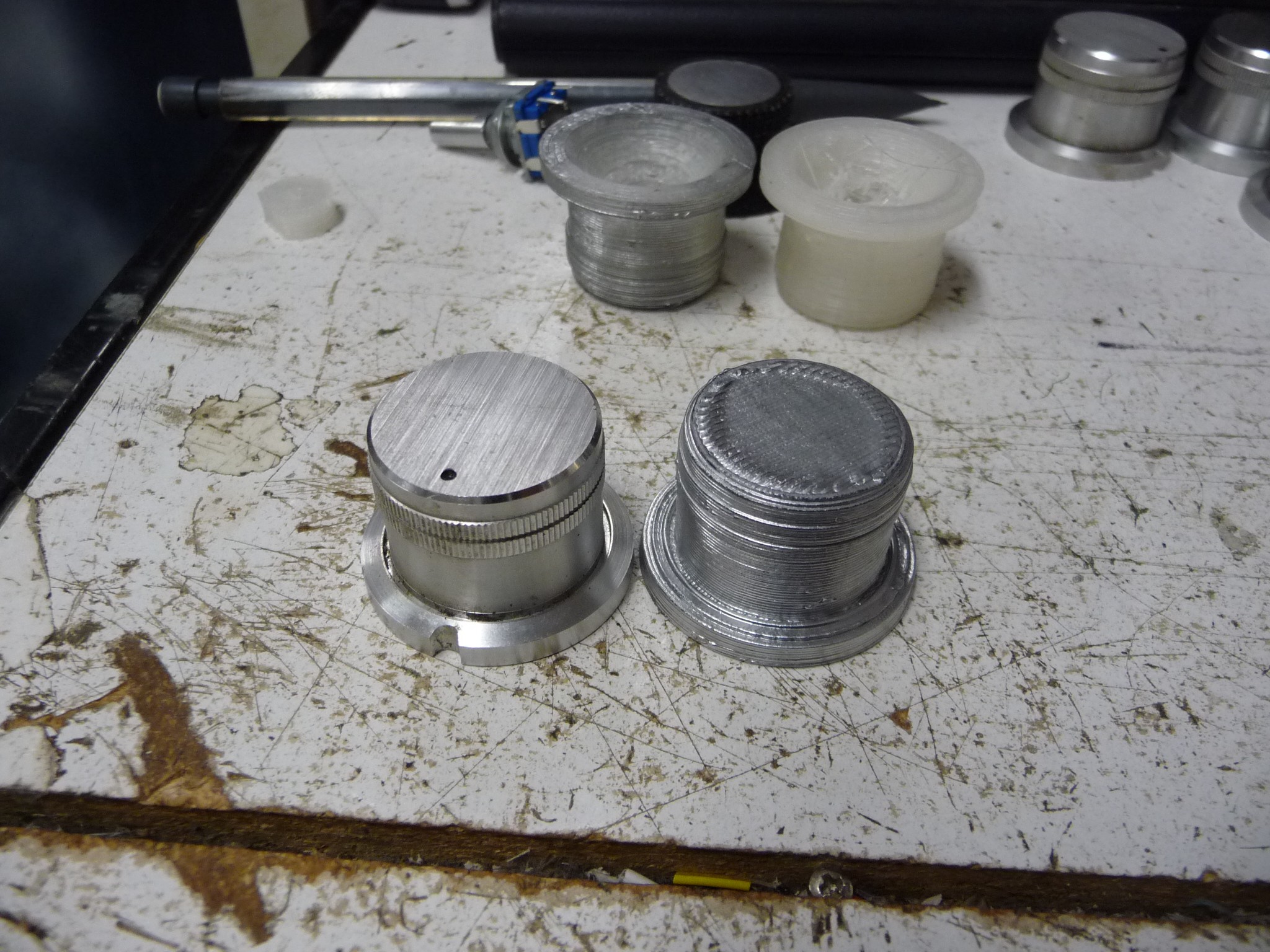
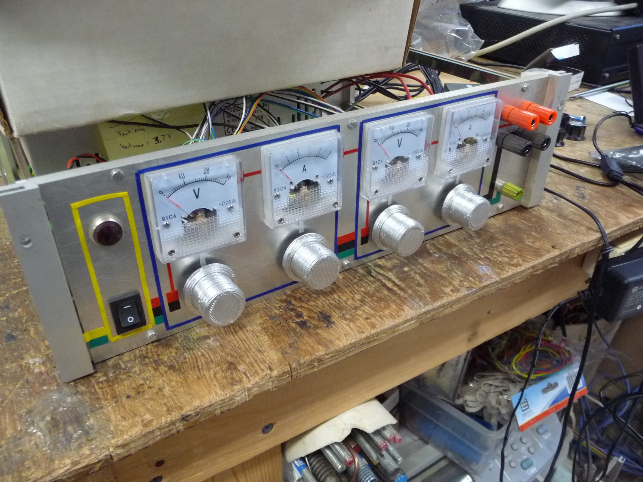
07/29/2015 at 03:38 • 0 commentsNight before last I sat down and worked on modeling the origional knobs I'd used so I could print some repalcements.
In the origional design, the knobs operated potentiometers, when that went wrong I changed to digital encoders. The potentiometers used a knurled shaft, but the encoders use a D shaft, so I had to give up the origional knobs.
One of the many project distractions has been the construction of a 3d printer, which I can now put to use to make some new knobs in the origional style.So, here is what I made.
![]()
They are a bit close to the old one, there is no point on notches and dots to indicate where the knob is , as its free spinning. yea, I painted it silver. I can think of about a million ways to improve the design of the knob, and I can do that later one day.
![]()
But for now, they are on the power supply. I think this is the first photo with the... pinstriping, I added :)
-
Revisiting the pwm genorator
07/26/2015 at 07:16 • 0 commentsK.C. Lee's comments and some thoughts had me revisit the pwm genorator for two questions.
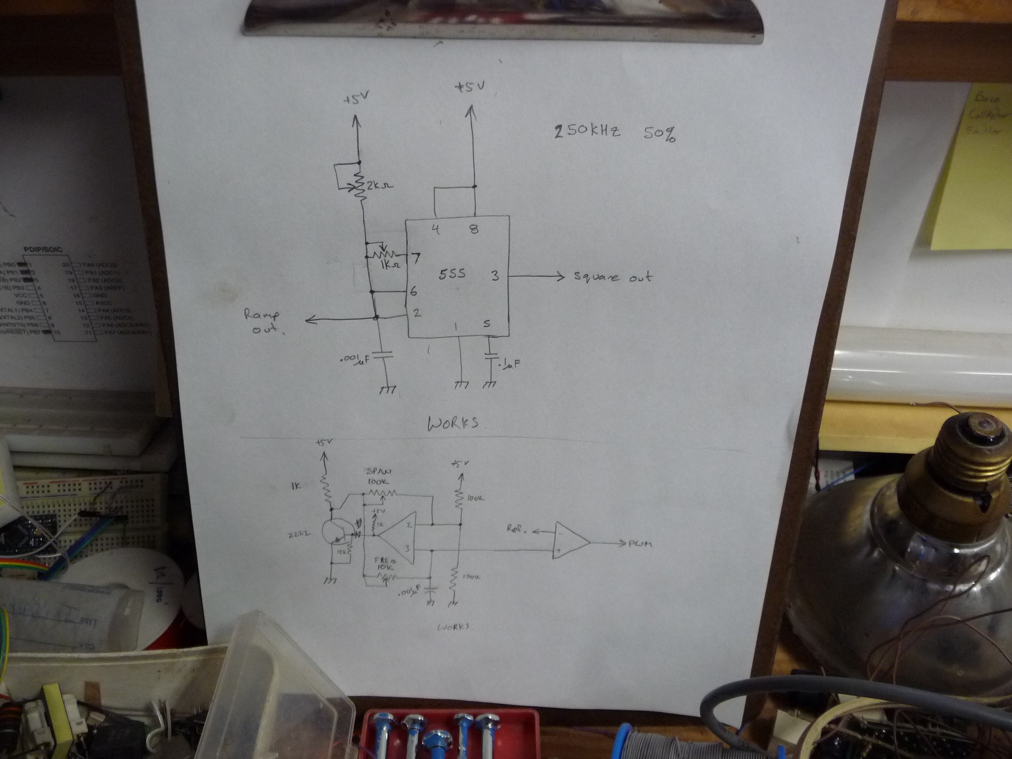
a) Would a 555 make a better ramp generator?
b) Can I get the whole ramp generation circuit to operate on 5V ( that previous design needed to be operated at 12V to get around shortcommings of the LM393 output )
Frist up was the 555, Operated in 50% duty mode. I was able to get it working, and it generated a fine signal. But looking at it on the breadboard I realized that it might not be best for the long term goal. If I use a 555 for a ramp genorator, I still have to use a LM393 for a comparitor to generate the pwm, so far the design also needs a 74xx14 to clean the pwm and synchronization signals, 74xx74 to alternate the phase drive signals, and 74xx00 to gate the pwm to the correct driver side. It would be preferable to not add another chip to the mix, If I can make the LM393 do teh work, its one less chip in the mix. (but it worked)
Next up was trying to adjust the LM393 circuit to operate on just 5V. The output of the LM393 is a common emitter NPN with a current rating of 16mA, To drive a .1uF cap at 250Khz, takes about 70mA. so, I put a PN2222 on the output of it to boost it up. Then I also lowered the bar, by switching to a .001uF timing capacitor. I suppose that means it only needs 0.7mA....
zippo:/files/programming/c# units
You have: .001uF*(3V/4us)
You want: mA
* 0.75hmm...
zippo:/files/programming/c# ohm -v 5 -i 0.00075
Wattage is: 0.003750
Current is: 0.000750
Voltage is: 5.000000
Resistance is : 6666.666504hmm.... interesting how these things dont come up while your hacking a circuit on a breadboard...
Anyhow, it worked, and it helps me reduce the chip count of this circuit. Since building it K.C. Lee fired me a schematic of his circuit, and I'd like to use the current source for my LM393
The other mental note is the power filter he used for it, which it a good point, make sure the osc has really clean power.
... I can go to .01uF and still not need the booster transistor...
below are the schematics I tried.
![]()
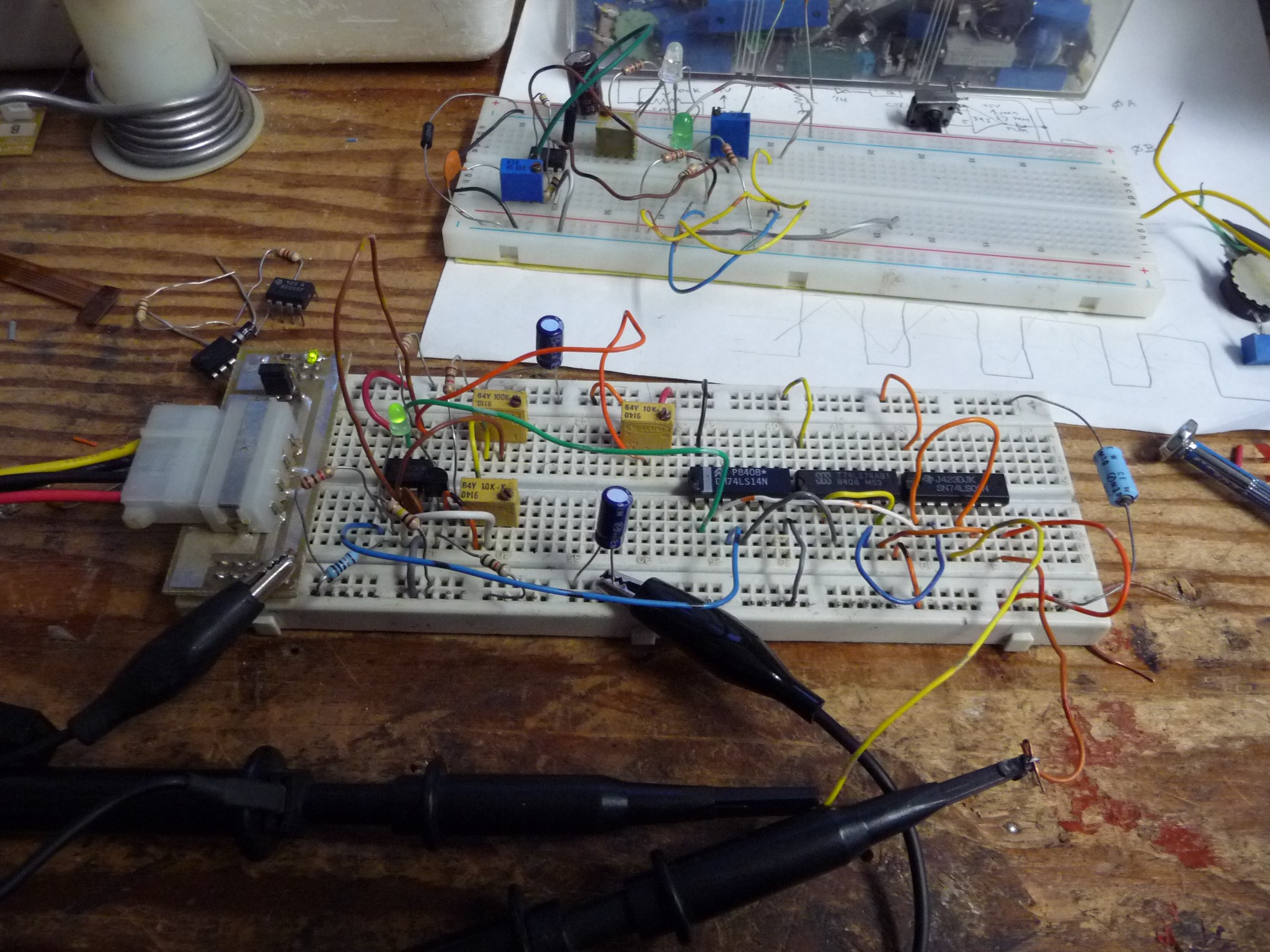
below is the LM393 circuit
![]()
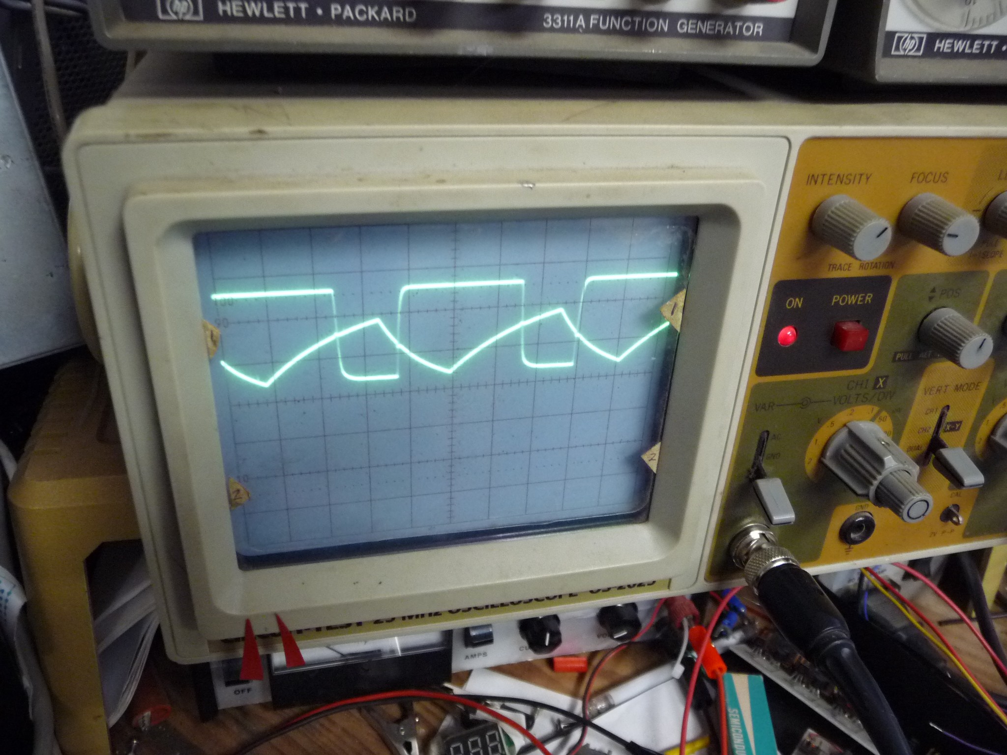
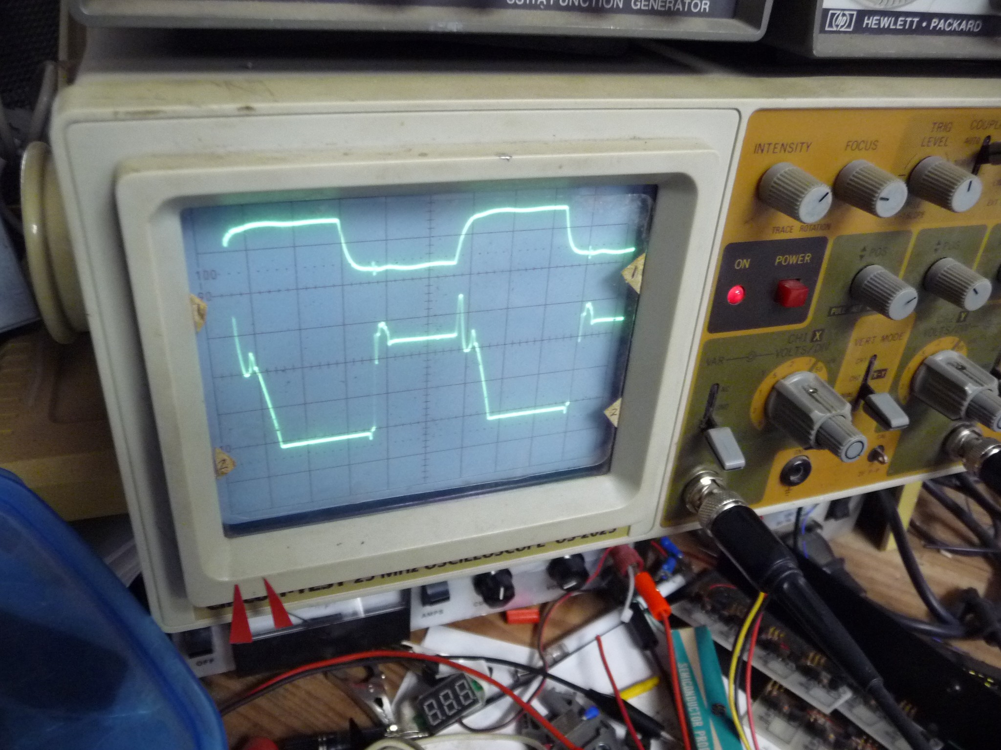
scope traces... (the signal I'm using for generating the pwm is ramped, but all that does it play with the phase of the pwm as the values go up and down)
![]()
below is the split pwm for sending off to the fet drivers, P channel fets, so low is on. This is the signal out of the 74LS00
![]()
Now if you will pardon me I'm gonna take out that transistor and try inserting a current source, ... which just puts a transistor back I suppose... ah well..
-
P channel Fet driver
07/24/2015 at 05:20 • 0 commentsSo, today was the attack on the fet driver. Last night I paged thru a lot of datasheets before finding a circuit that I thought would work out properly for the project. Interestingly enough, it basically just offsets the drive signal of a low side fet driver, which is exactly the type of solution I was interested in.
With 2 possable varriations, I have working circuits.
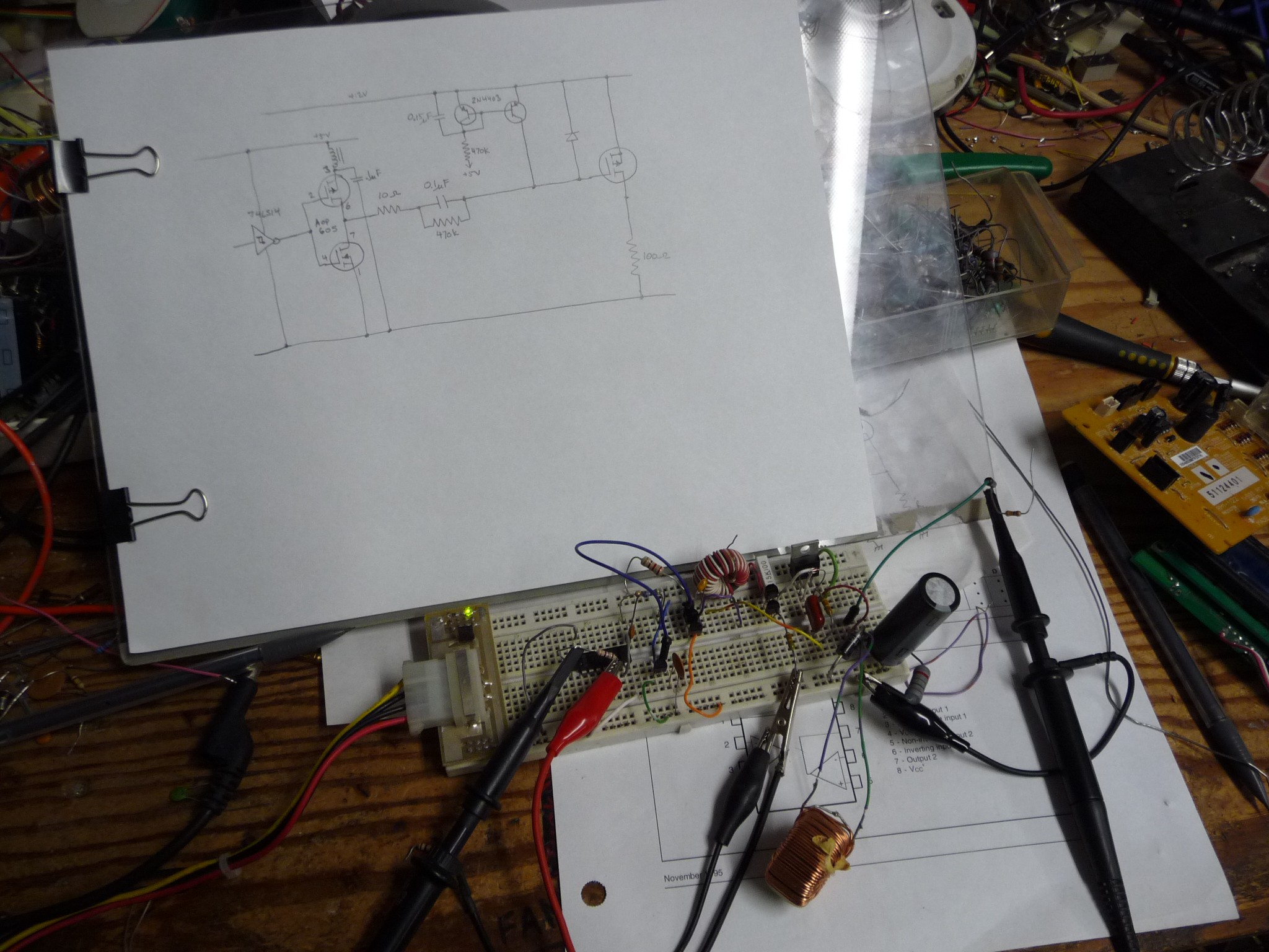
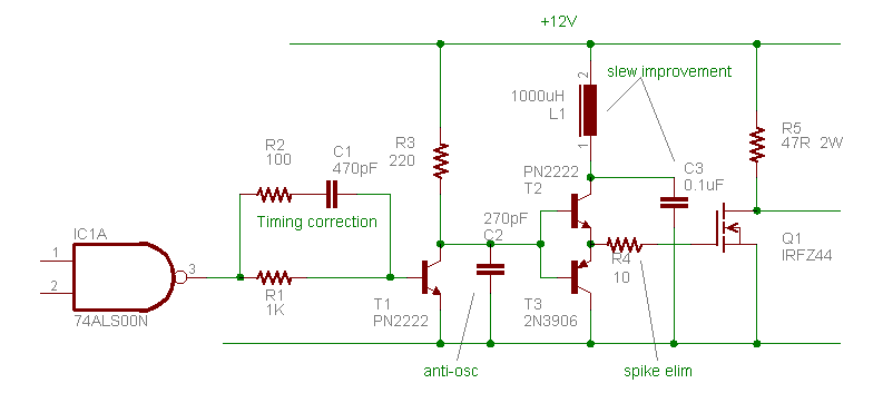
I was playing with the gate driver for the power fet, I have two circuits available, one is a bipolar totem pole driver, and the other is a fet totem pole driver. the photo below is the bipolar, but the only way I was able to get the performance I wanted was to bump the drive supply up to 12V from 5V (need 10V anyhow) and to put an inductive load on the power fet that would respond faster to the switching. I want to go back and try the fet drive.
At the end of the day, the circuits on time is 0.25us, which might sound good till you realize that at 250Khz, the on time is only 4us. I can lower the switching freq if I need to, 250Khz was a bit of an insane goal. (but I'm doing awefull well)
![]()
![]()
my alternate power fet driver is...
![]()
So, now I have a regulator, pwm genorator, and fet driver, the only other part is to make a buck filter and put it all togethor. (it wont be as easy as it sounds)
And the old bench supply burned out AGAIN, I dont know what did it this time, last time I had to replace the LM723 controller in it.
-
250Khz pwm converter!
07/22/2015 at 06:12 • 8 commentsI couldn't help myself, I had to try to design a switching converter. The problem that I'v had so far with this, is that driving an N channel fet causes drive signal in the output, which throws it off. Using a P channel is a bit easier as there is no extra drive voltage to generate, I'v found a P channel fet that has a low enough Rdson, but the remaining problem was the offset between the 5V control signals and the 36V main power rail.
The easiest way to offset a pwm signal for a fet is to use a series capacitor, but thats only suitable for duty cycles up to 50%.
So a solution clicked, to split phase the pwm converter. I can push the series capacitor just a bit past 50%, so 2 phaes is just fine.
I just tried a circuit that, with some persuasion (to get it up to 250Khz, the LM393 was the only thing I could find that could do it), it works. I didn't try this with a power stage, the goal is just to design a pwm controller.
![]()
![]()
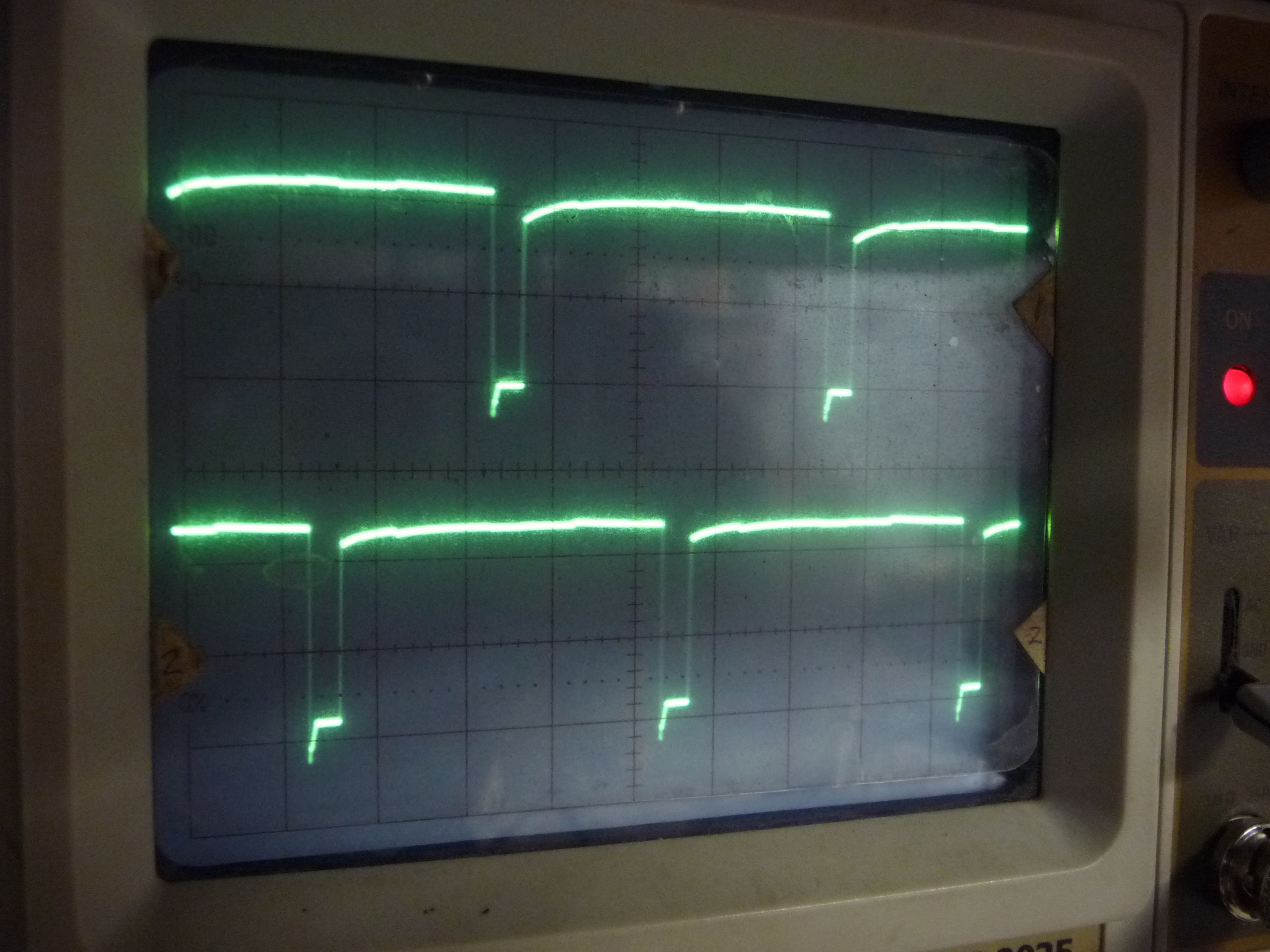
Above image you can see the output of the flipflop on the bottom, the pwm wave on the top. The flipflop output is used to select which channel the pwm pulse goes to.
I think I can peel a power stage or two off an old motherboard.
This is exciting, I can use this converter as a power stage with the regulator in the previous log.
But a question burns deep in me, is there no way to use a single chip smps chip open loop to generate the pwm? (the regulators dont behave properly to use directly)
-
regulator success!
07/10/2015 at 04:04 • 0 commentsKinda, its linear, and I have a few minor tweeks, but its working
![]()
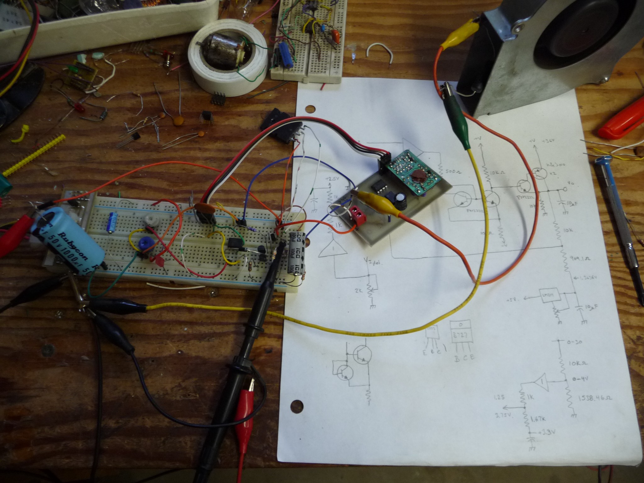
It is successfully amplifying the voltage and doing the current limiting, without a whole bunch of oscillation. with all the recent math, bringing all the signals to the DAC levels isn't a problem. This all looks good.
... of course in the process of getting it working, i tweeked it, the next step is to revese engineer what I just did.
p.s. at the end of this month there will be a 3 month stall in the project :p
p.s. thanks for those who are watching the project, your really keeping me motivated to work on it.
-
A bit of regulator progress
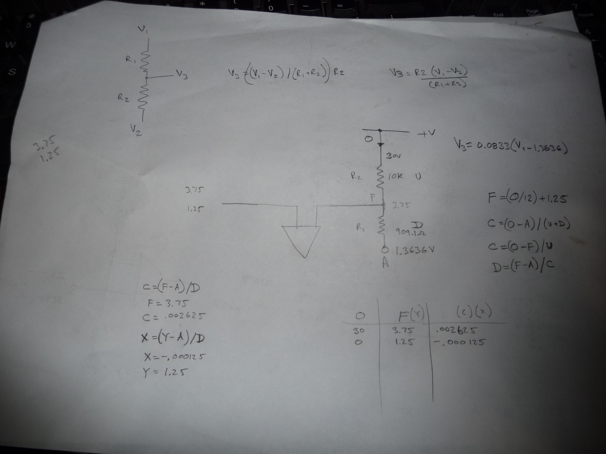
07/06/2015 at 14:27 • 0 commentsAfter 5 hours of torturing wolfram alpha with equations (that once I worked out, I could have just done myself), I managed to design a voltage divider for the feedback that will take the output signal to the same voltage range as the DAC outputs. this will reduce a bunch of complexities and save a lot of parts. I'd still like to have a dac that output a larger voltage range, oh well.
0-30V in, 1.25-1.75V out
![]()
I'm planning to put togethor another regulator circuit soon.
And it gets better, being that I worked out how to do it, I wrote a program to solve these offset votlage dividers for me.
int main(void) {
float R1, R2, Vin1, Vout1, Vin2, Vout2, I1, I2, Voffset;
printf(" Vin \n");
printf(" R2 \n");
printf(" Vout \n");
printf(" R1 \n");
printf(" Voffset \n");printf( "Top resistor: ");
scanf("%f", &R2);
printf( "Input low value: ");
scanf("%f", &Vin1);
printf( "Output low value: ");
scanf("%f", &Vout1);
printf( "Input high value: ");
scanf("%f", &Vin2);
printf( "Output high value: ");
scanf("%f", &Vout2);
I1 = (Vin1 - Vout1)/R2;
I2 = (Vin2 - Vout2)/R2;
Voffset = ((I1*Vout2)-(I2*Vout1))/(I1-I2);
R1 = (Vout1 - Voffset)/I1;
printf(" Voffset is : %f\n", Voffset);
printf(" R1 is: %f\n", R1);
return 0;
}Using that confirms last nights work, and to adjust the current signal, I use two 10k resistors with an offset voltage of 2.5V
root@blackie2:/files/programming/c/resistor# ./OFFSETDIVIDER
Vin
R2
Vout
R1
Voffset
Top resistor: 10000
Input low value: 0
Output low value: 1.25
Input high value: 30
Output high value: 3.75
Voffset is : 1.363636
R1 is: 909.090942COOL!
-
Output regulator
04/23/2015 at 03:16 • 0 commentsWeek before last I went thru about 9 regulator designs that dont work well, I could post them all, what I was left with was one that almost works, has some good ole oscillation that needs to be quenched.
"I'm not dead yet!"
-
distractions...
03/16/2015 at 01:33 • 0 commentswow, 3d printers, are REALLY distracting. I'm just working on an analog regulator again, there are two projects mentioned on HaD that I'm drawing ideas from. I do need to finish this supply.
Bench power supply
USB and manual control, and monitoring, 2 channel 5A 30V bench supply.
 Rue Mohr