AVR
AVR-
Components Are In, ITS HAPPENING
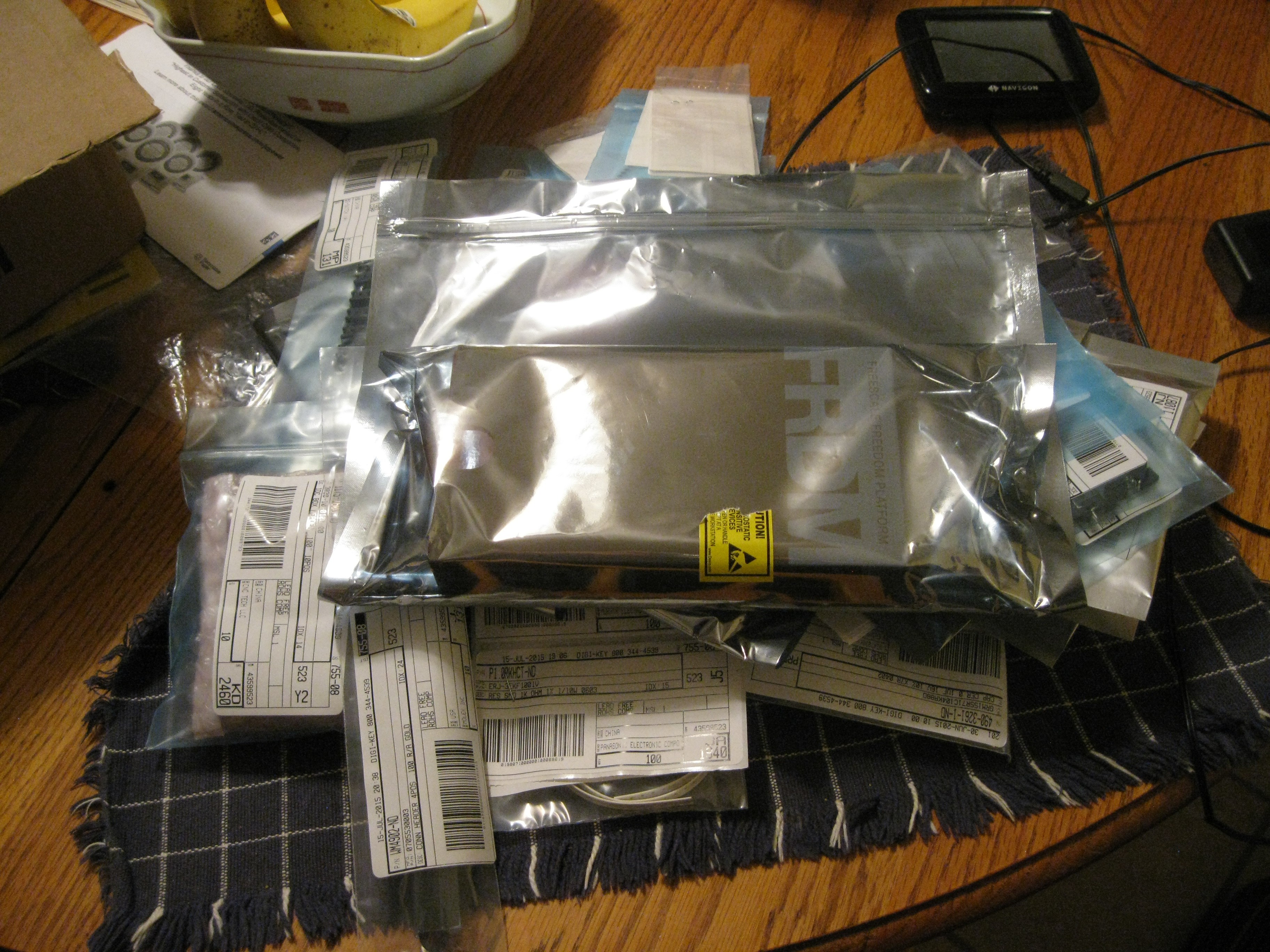
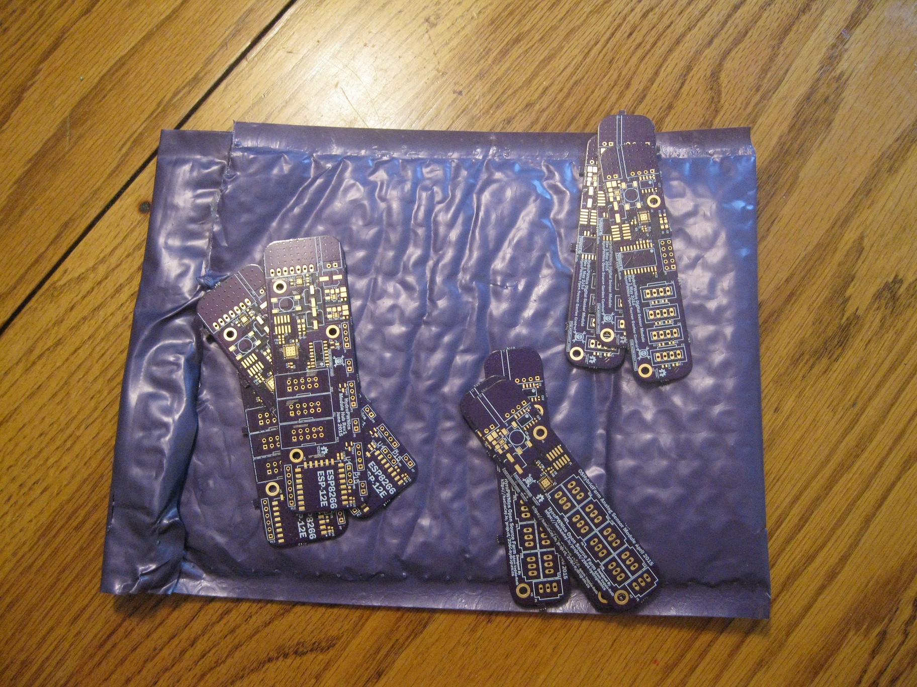
07/22/2015 at 07:03 • 0 commentsToday UPS arrived with my Digikey order containing all the components to build revision 1 of the HydroPWNics hardware. I am hoping to solder and test the hardware this week, and get each board functioning/ready for development. If there are any problems or mistakes in the design, I'm going to attempt to modify the PCBs with wire and trace cutting, and if that cant render the current hardware revisions functional next week will be dedicated to revising the PCBs. If the PCBs are functional or repaired to function the plan is to spend next week on the embedded software. Here is what the pile of parts looked like:
![]()
So yeah yay parts! So as for populating these PCBs successfully without damaging components I have sort of a protocol I follow for populating boards. With a prototype I like to do manual assembly placing each component on one at a time under a stereo microscope. I like to ensure that every single component is soldered on perfectly to prevent shorts and keep components well secured to the pads. Now when the PCB is populated I do it in stages/sections rather than solder on all the components, cross my fingers and turn on the power. I found that that method can result in blown components and that's not fun for anyone, components cost money and can be difficult to remove depending on the package. The first stage/section thats populated is the power supply, whatever it is composed of in the case of these board a decoupling cap and a regulator. After the power supply is populated, I inspect it for shorts under the microscope and power it on. The goal is to debug the power circuit and make sure it is function correctly. The next thing I do is manually test all the pads that should be receiving power and make sure they are recieving the correct voltage (some designs have more than one voltage). In the case that the design has a more complex power circuit such as the module hub with its two regulators, then the process is the same except one regualtor is populated and tested before the other. The next stage for population and testing really depends on the topology of the PCB, in this case the hydroPWNics boards are microcontroller boards like most of my projects tend to be. In this case the next thing I populate and test is the micro controller and its supporting passive components everything it needs to boot up. After the microcontroller is soldered in place with its supporting components I power it up and attempt to program the micro, if it is succesfful I just populate the rest of the board if not consult the datasheet and figure it out! Thats basically my PCB population protocol I'll try to cover each section of the population of each board in the next project log.
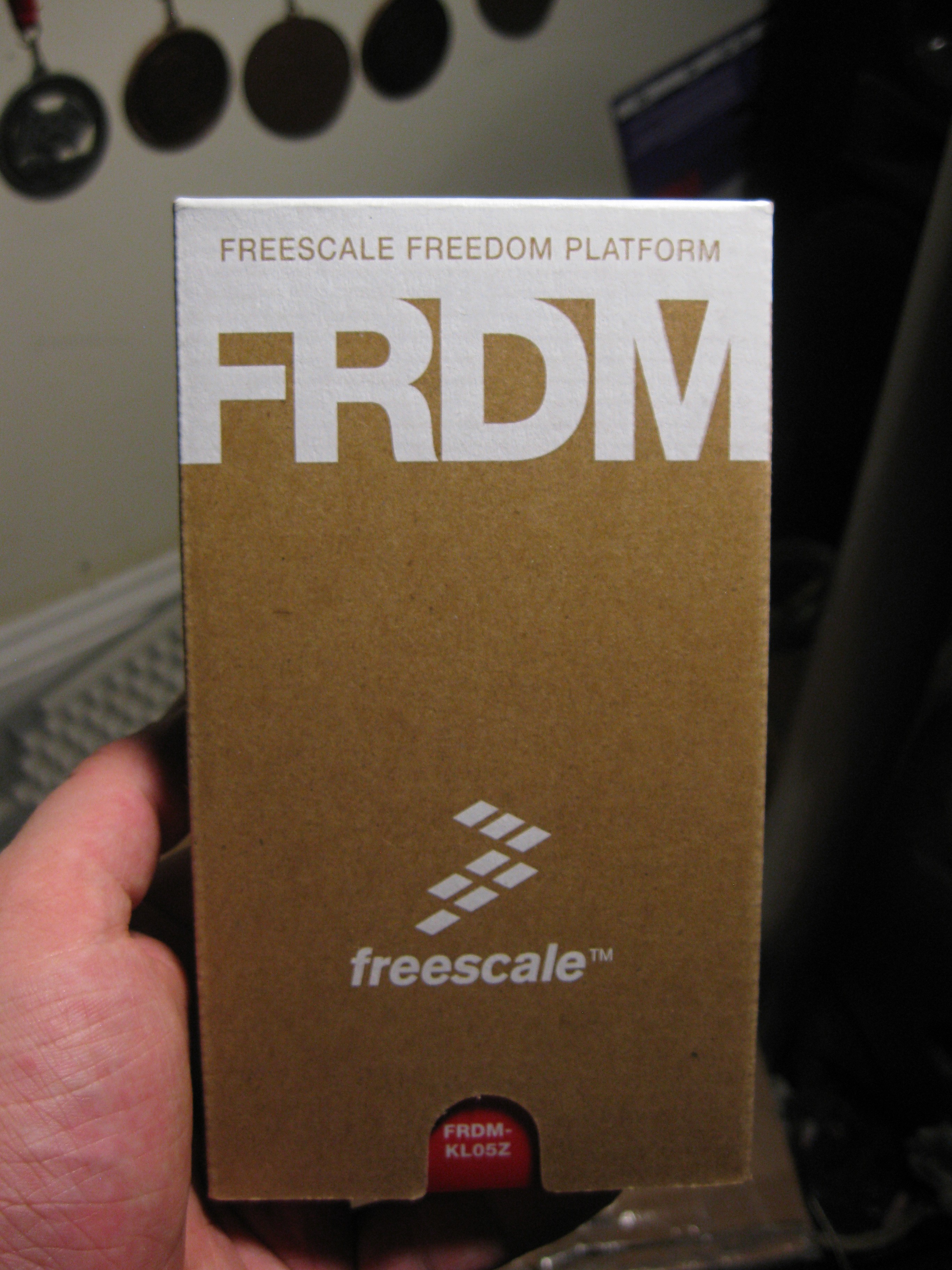
Amongst the components in the box from digikey was something else. I also purchased a FreeScale FRDM-KL05Z Freedomboard, this will function as a development tool acting as a dev board and programmer for the two sensor modules. I do also believe I will be able to program the Module Hub with the OpenSDA debugger built into the Freedomboard but I have yet to test it. Anyways I thought the packaging for the little board was pretty neat so here a picture:
![]()
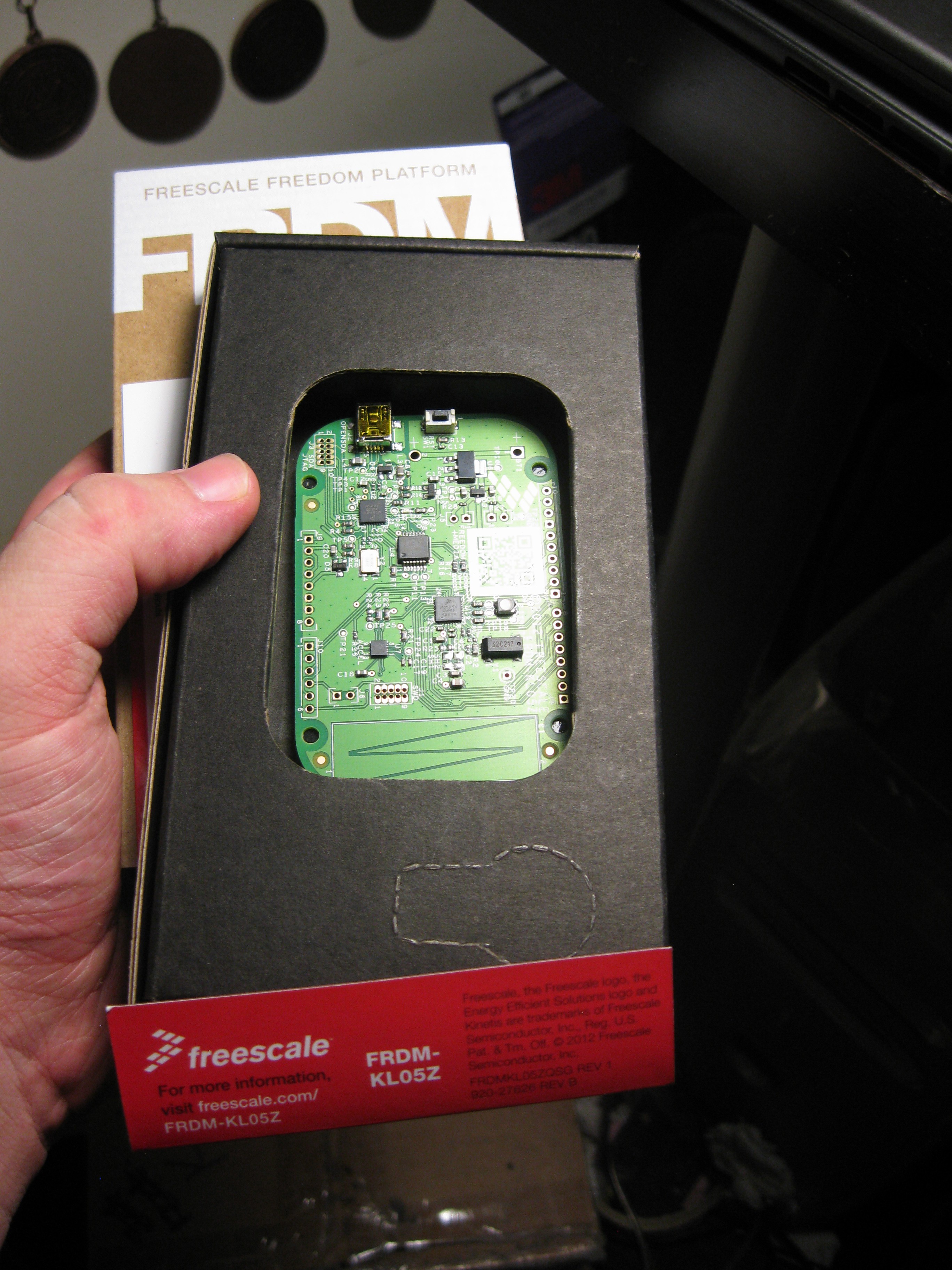
Open Box
![]()
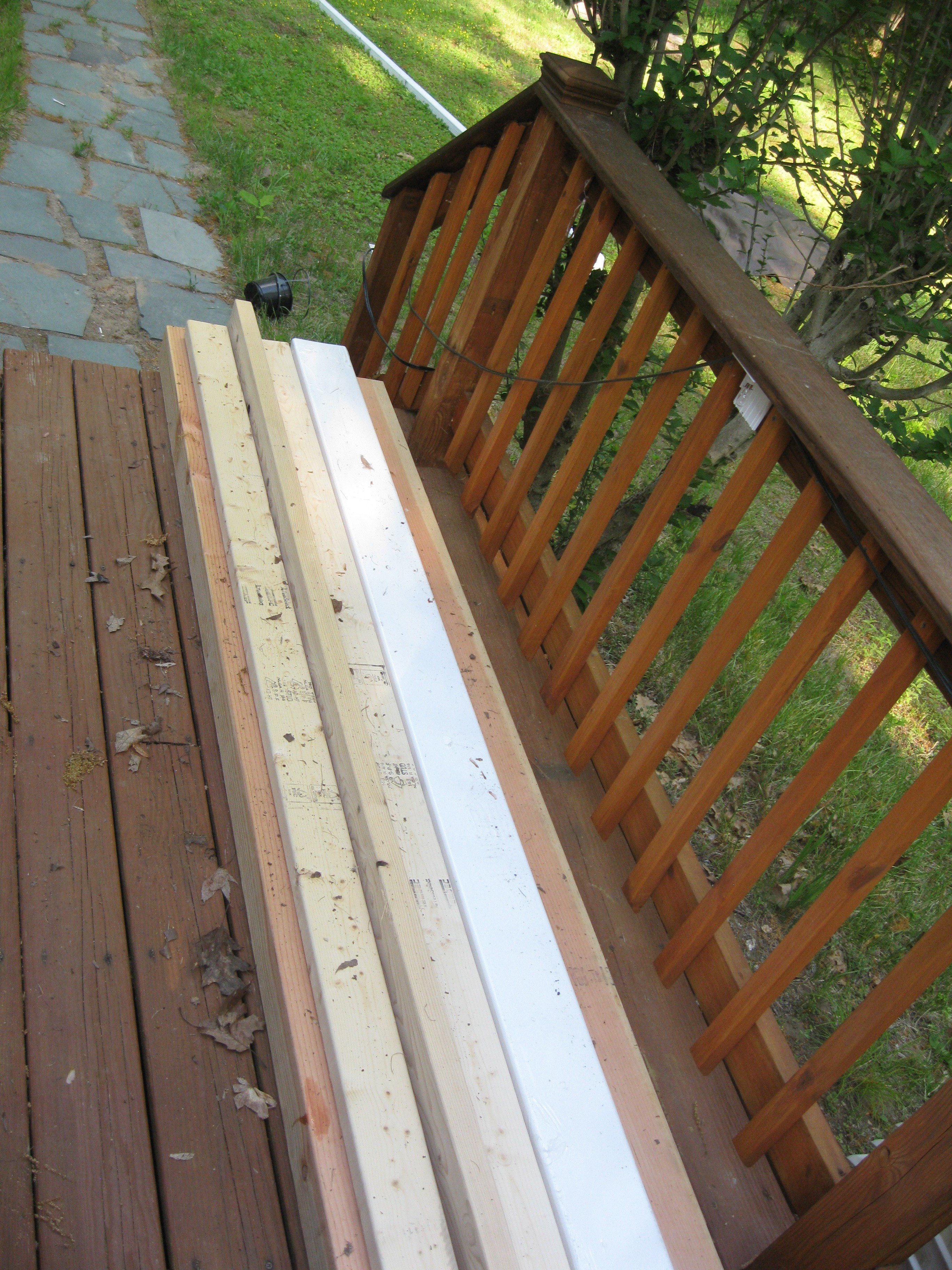
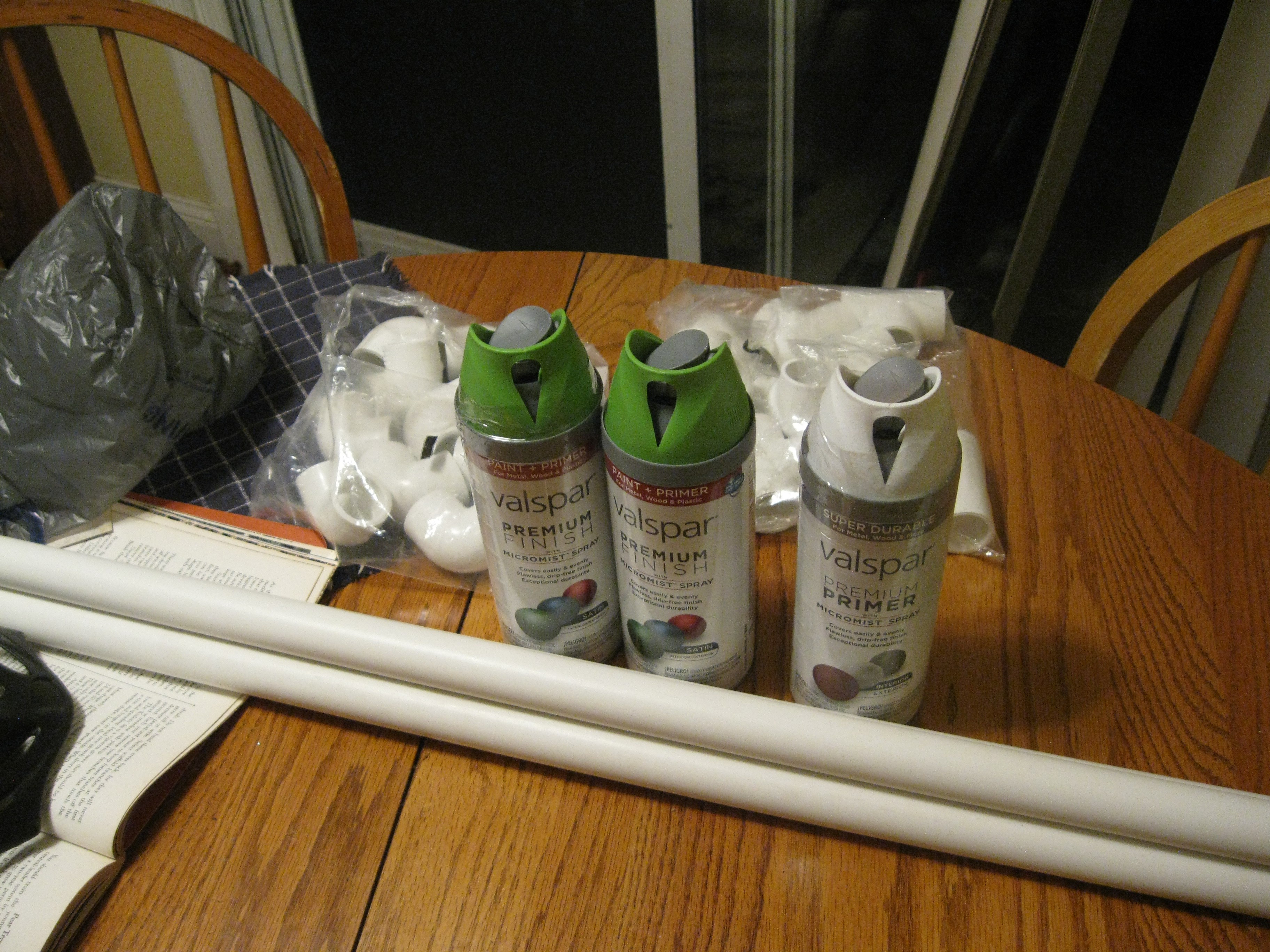
On another note, I went out to the hardware store today and picked up some more supplies for the NFT rig I will be using to deploy and develop HydroPWNics with. I got more PVC pipe for the fitting I have, the missing endcaps for the posts, and some spraypaint for the frame. I got a cool matte green color and some primer so this thing is gonna look pretty. Endcaps not pictured, I couldnt help myself and put them on as soon as I got home.
![]()
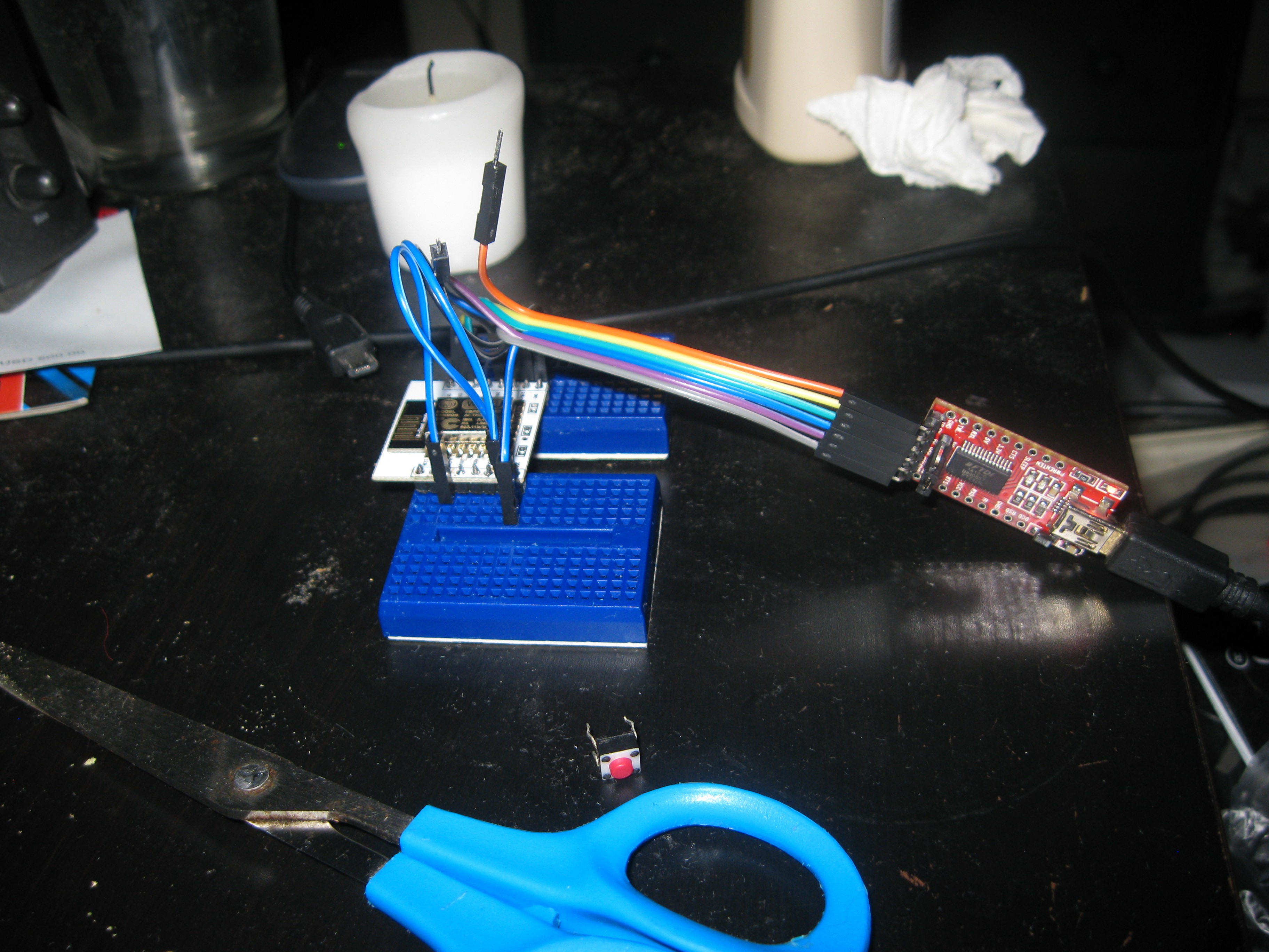
And one more thing, a while back I bought a ton of ESP8266 stuffs on ebay for development and projects. I grabbed up enough ESP-12E modules for populating the Module Hub PCBs but also got a breadboard breakout kit. I soldered it up a while ago and didn't do anything with it. Last night I wired it up with some mini breadboards I had lying around to an FTDI breakout. I just wanted to test the module since i heard counterfeits of this particular one are common. To test the module I loaded example project code from the Arduino IDE with ESP8266 support, I'm happy to say that the module programmed successfully a few times, next step now is to setup the toolchain and learn how to build projects for it that way.
![]()
-
Update, Grow Unit build, Prototypes, and Software
07/20/2015 at 04:01 • 0 commentsThis week I managed to get a bit more done, a little bit of work here and there on each of the different parts. At the start of the week I ordered all the components for populating the PCBs, they should be in from Digikey after the weekend. I went through my inventory of components on hand and decided to just order all new components, to keep things simple, it ended up being a lot cheaper than I originally estimate too.
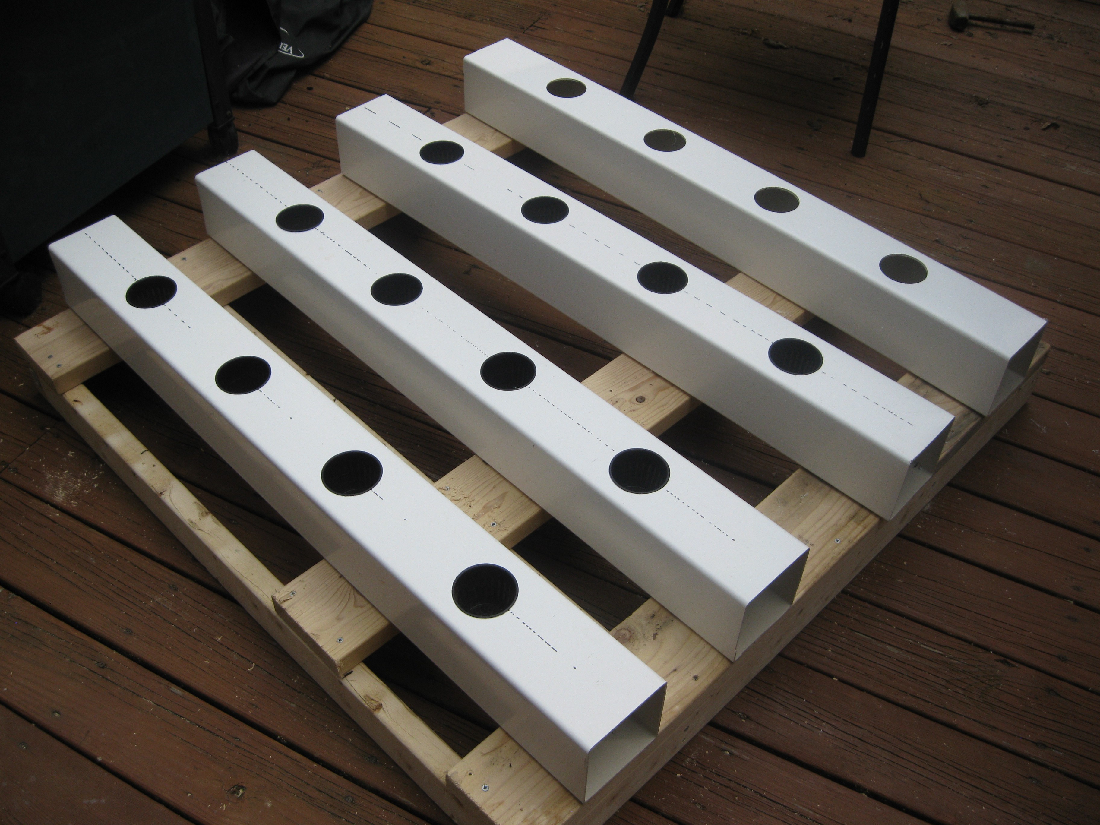
During this week I also got a lot more done on the grow unit. With the help of some friends I went to the local hackerspace's free night and drilled out all the wholes for the pots in the fence post. Unfortunately I forgot my camera so I don't have any pictures at the space of the drilling.
Posts all drilled with pots in all but 4 positions, see that the frame isn't finished, more on that next!
![]()
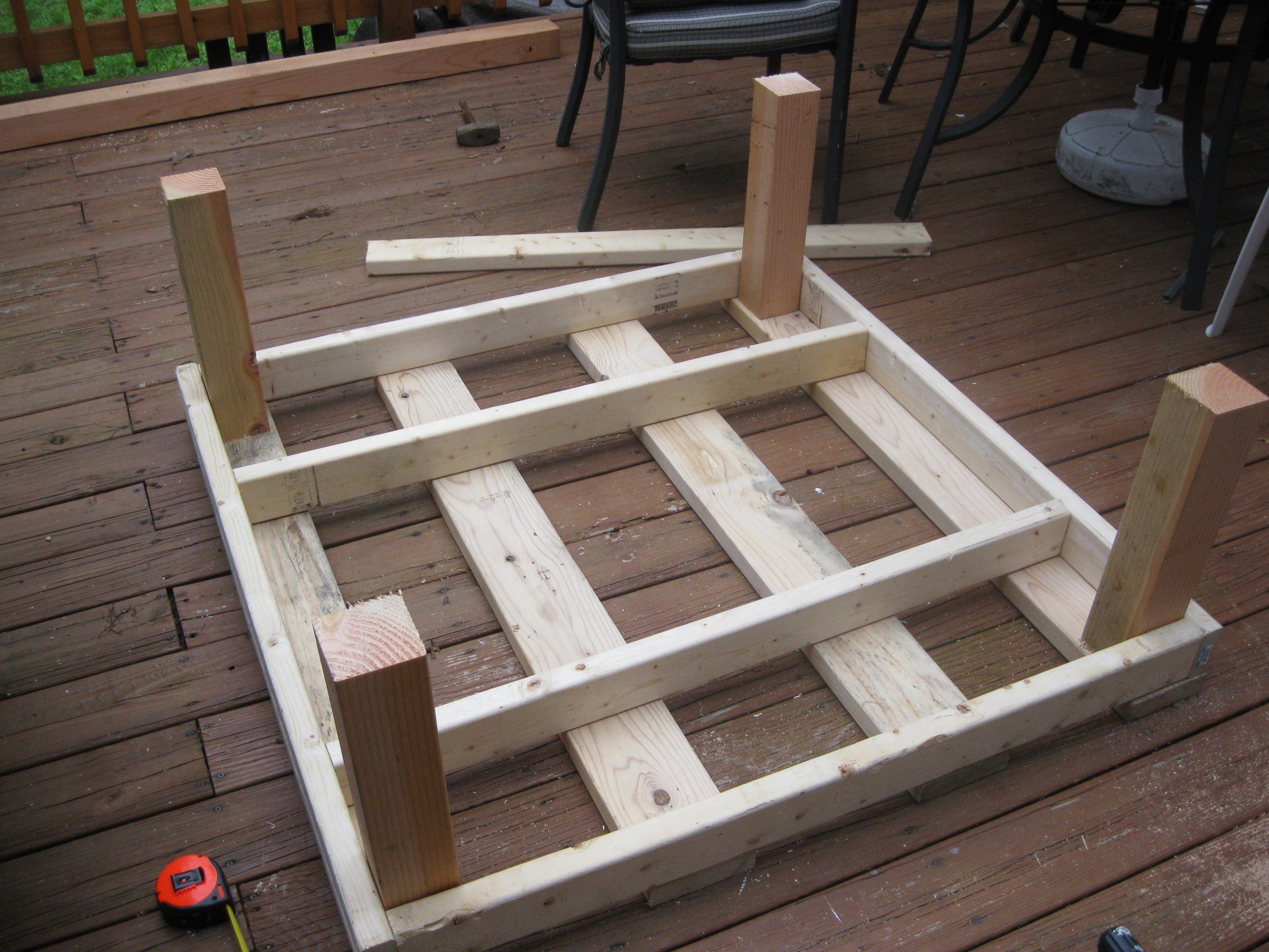
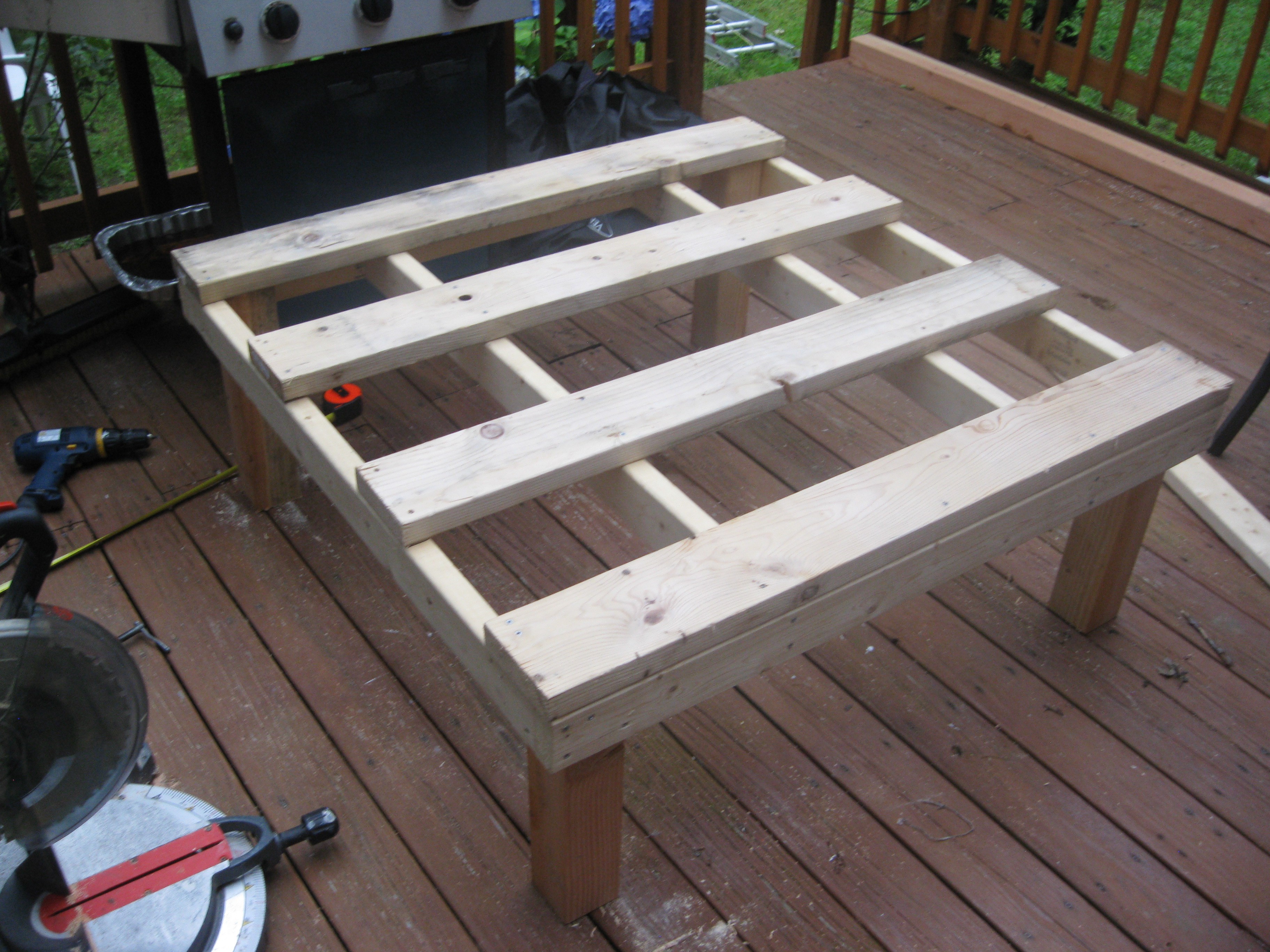
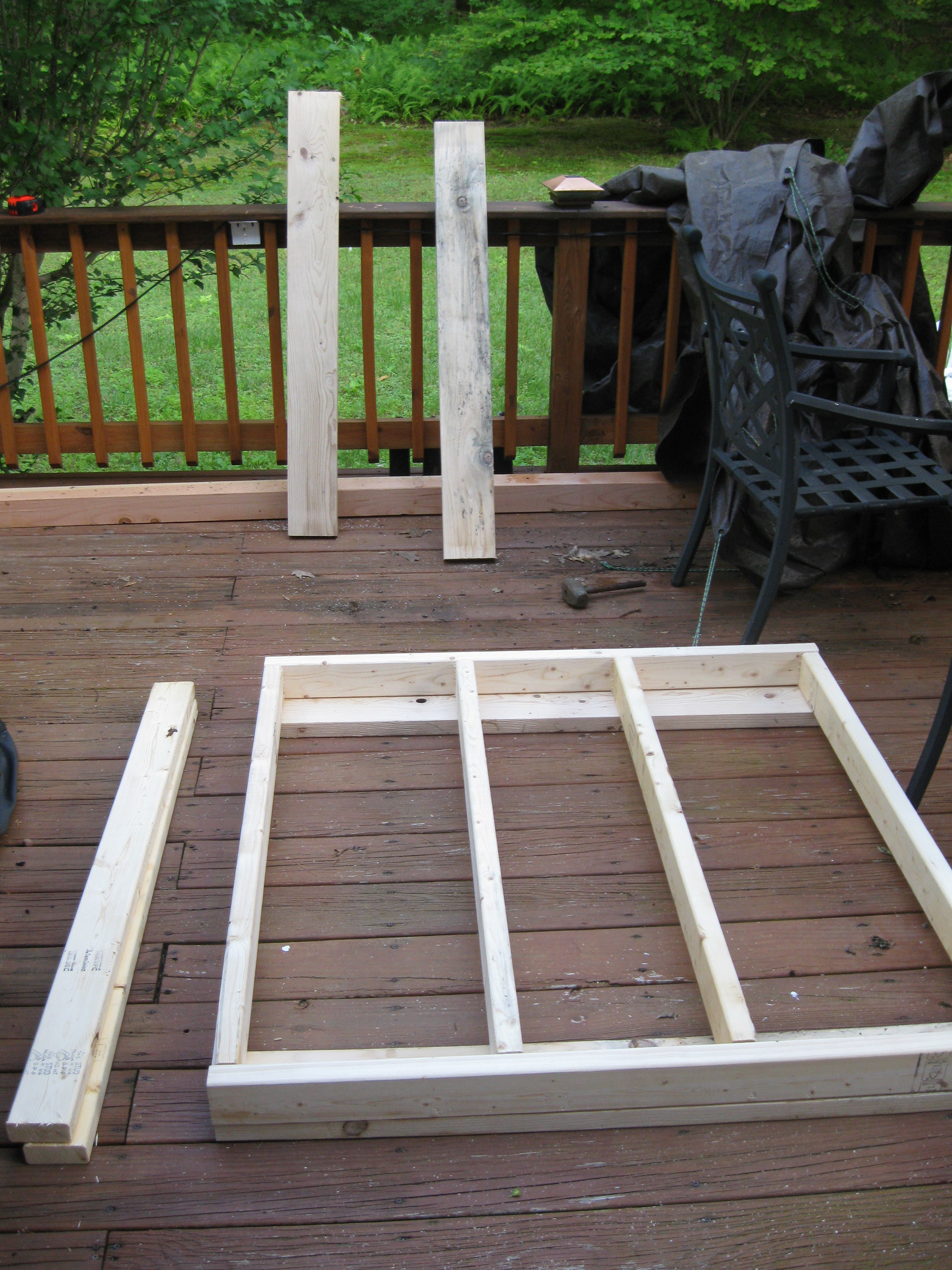
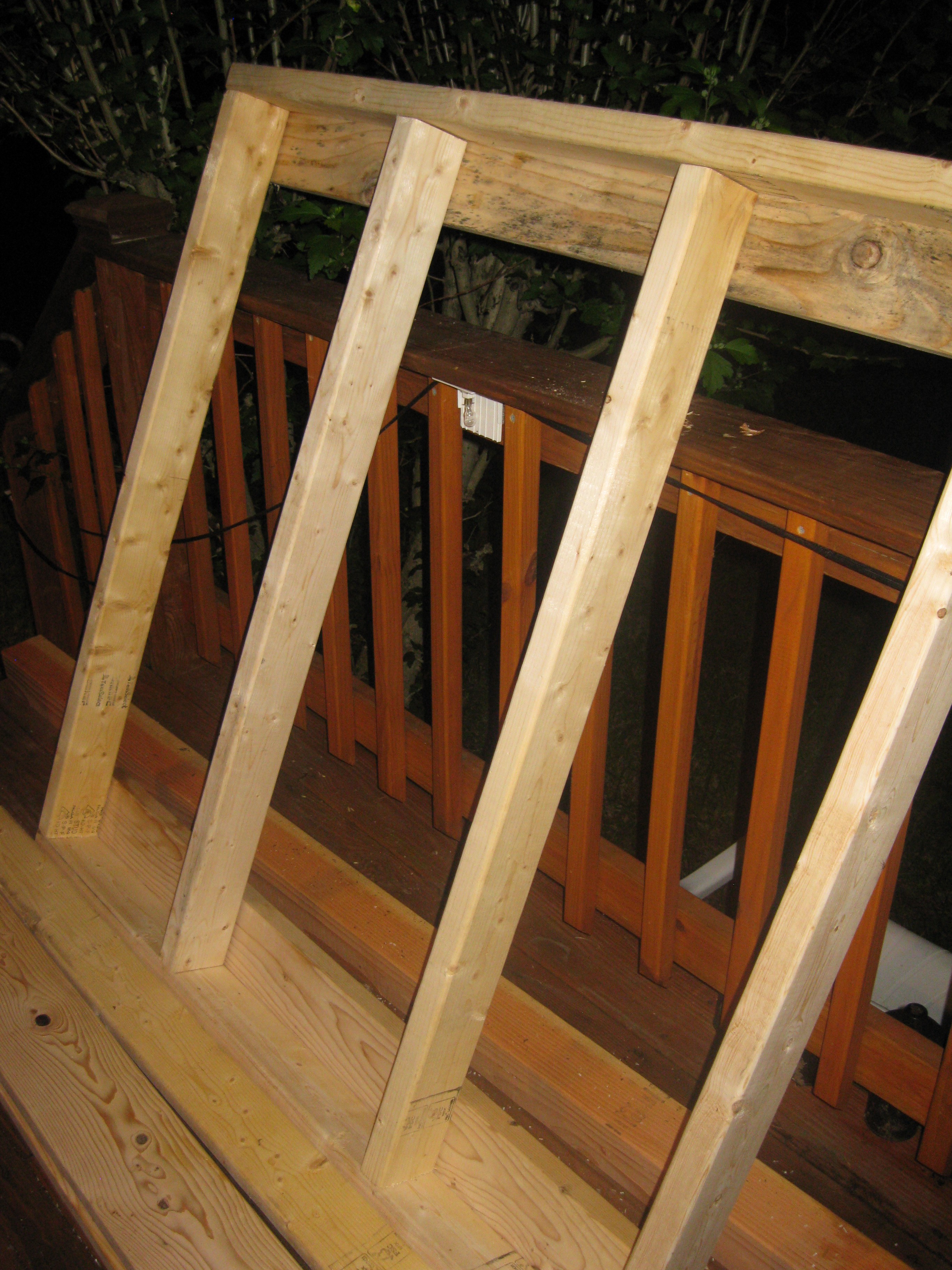
Today I finished the wooden frame of the whole unit. I added the crossboards and legs, take a look at the pictures to see what I mean:
Dry fitting the legs after the cross boards added to the top of the frame.
![]()
![]()
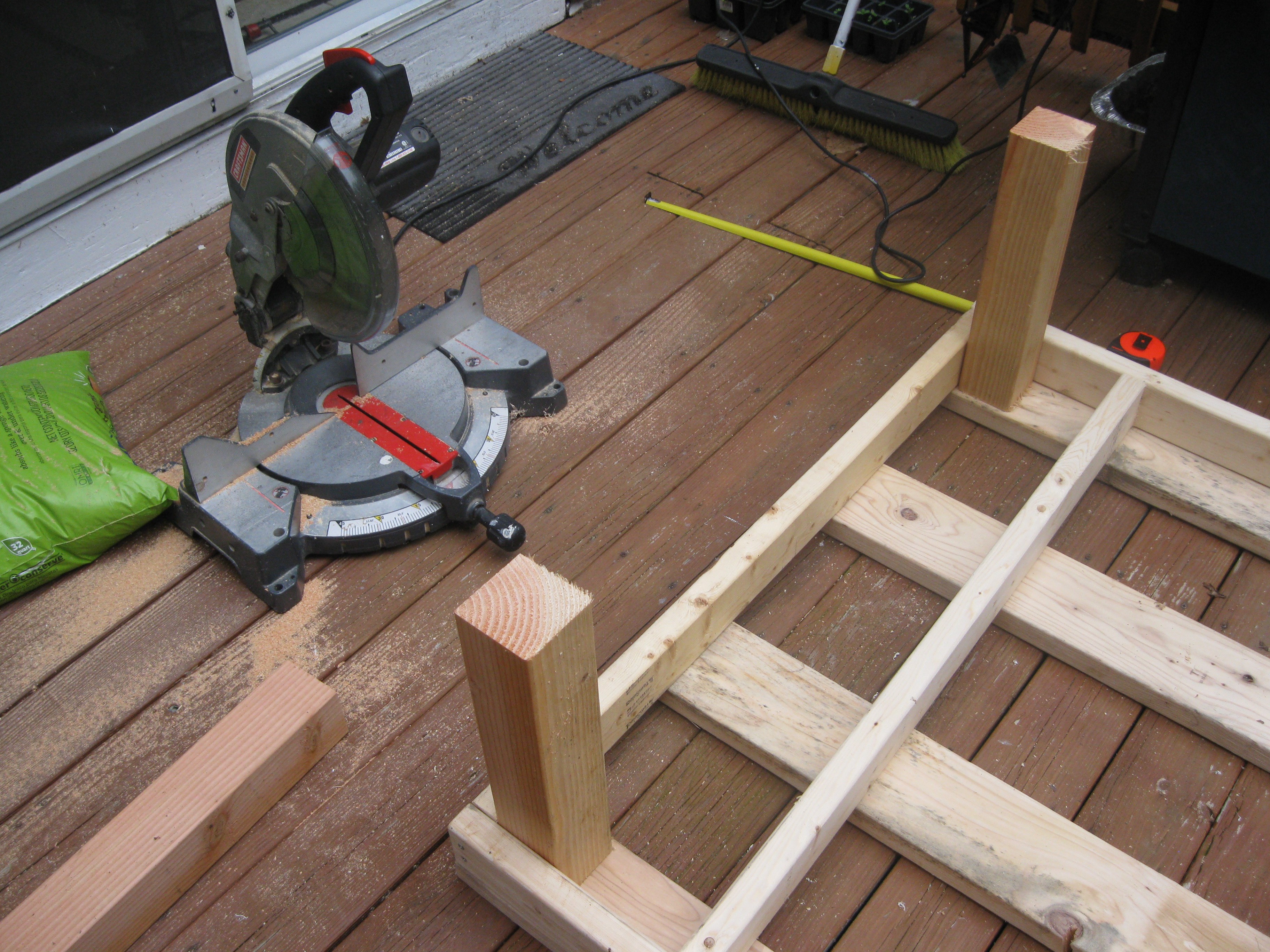
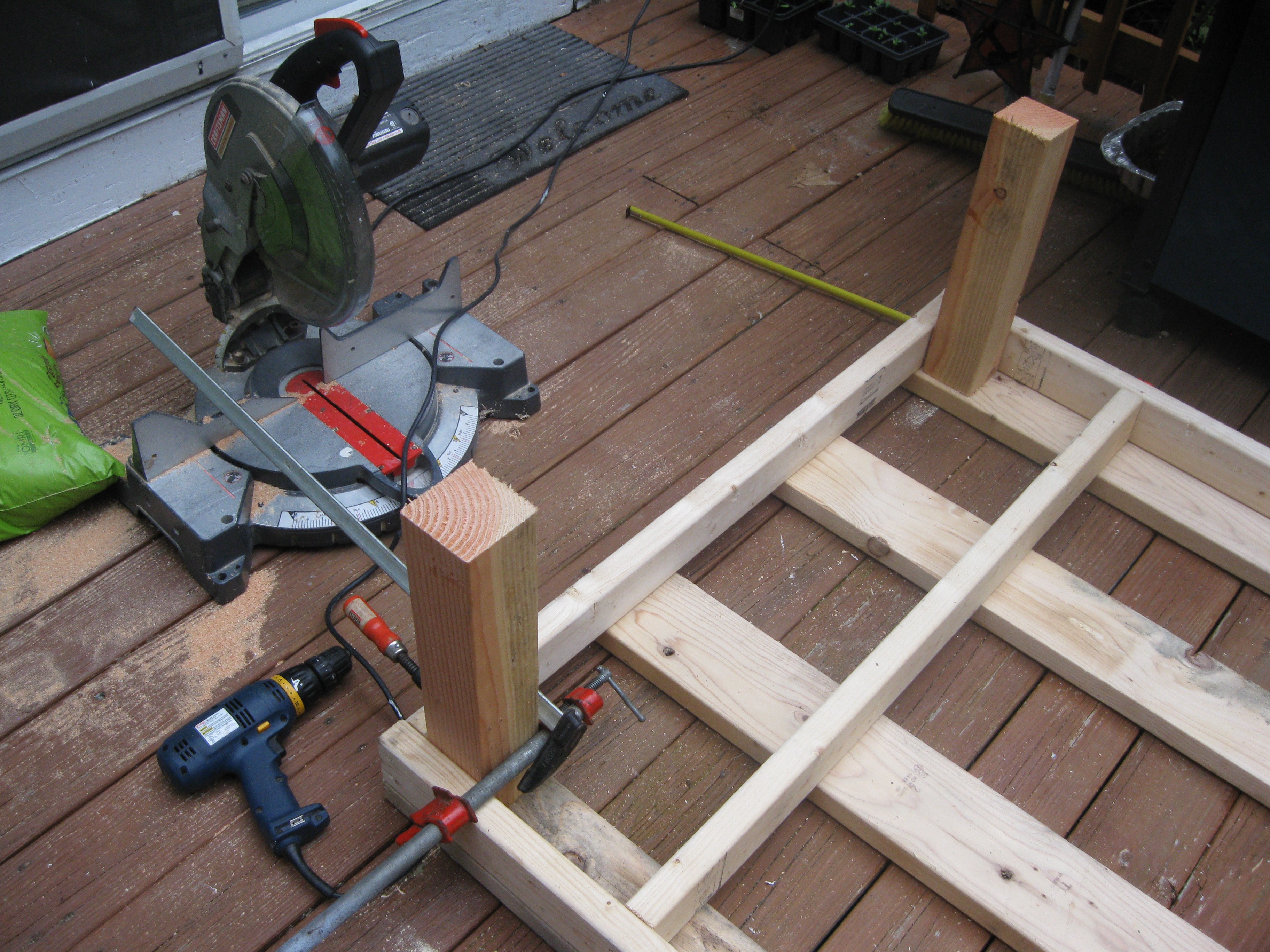
To attach the legs securely and straight, I clamped them tightly into each corner with the same two clamps I used the other day. I used a spare piece of the 4X4 wood to hammer each leg after being clamped to make sure its flat up against the board on the top of the frame. I used 4 screws on each leg. I'm trying to decide if I want to have crossmembers between the legs or have a skirt for the frame at the bottom, or both. I think a skirt at the bottom is definitely going to happen, mainly so I can build a giant drawer underneath the unit to store the water reservoirs.
![]()
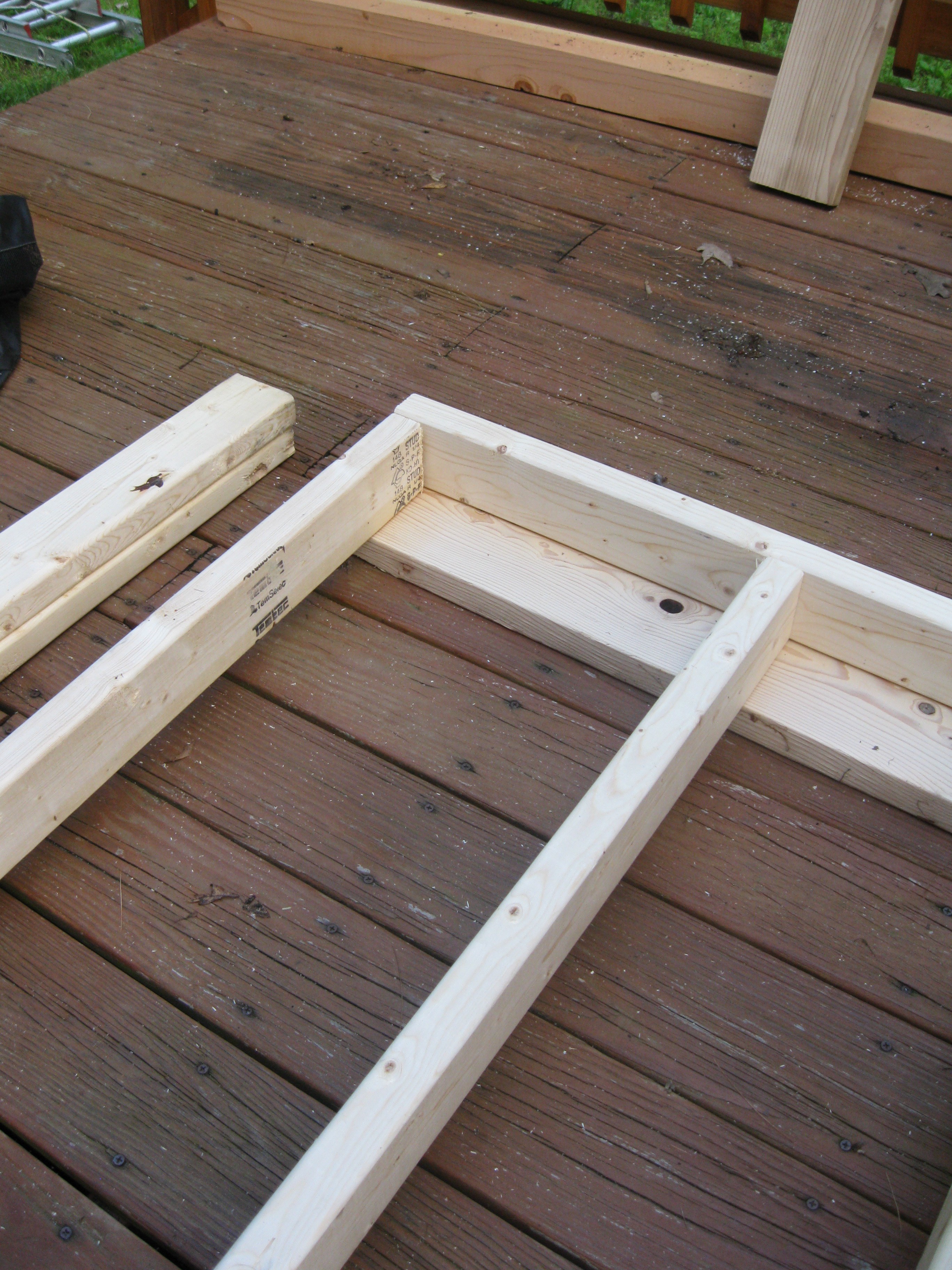
Another view:
![]()
Done for now, there will be a two by four skirt added to the bottom (as I stated previously), next trip to the hardware store I will be getting the remaining wood to build the skirt and bright green paint!
![]()
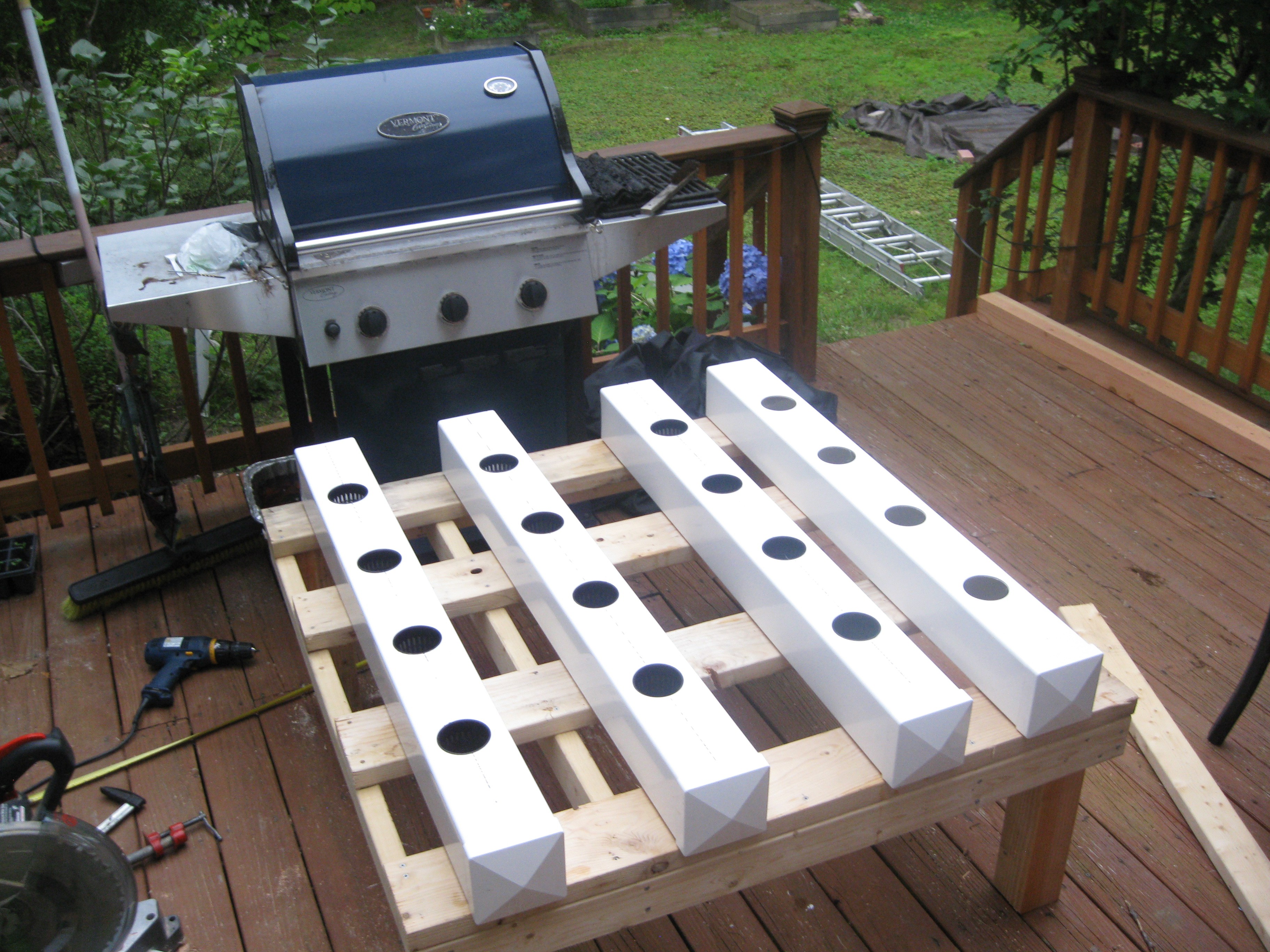
What it looks like with the rows of fence on top:
![]()
Overall I like how the frame came out, its almost a perfect 4X4 foot square and a little less than two feet of the ground. Orignally I was going to make it 5 tall off the ground, but I wanted more height for the plants to grow. I am also going to be using rubbermaide tubs for a reservoir instead of a 55 gallon water barrel which was also another reason to make it shorter.
As for software updates I did some more basic test work on the embdedded side and made some changes to how the GUI will be done. The GUI to control HydroPWNics will be just be a Jquery web application on a web page that the user logs into. The application will receive data to display from the cloud data server and send/receive JSON packets to the Java application running locally on the beaglebone black. With all these changes I should also mention that user Shane Kirkbride has joined the project offering his Microsoft Azure based cloud data system for plants.The platform is called Viva Planet and can be found here: http://www.vivaplanet.io/ I will be adjusting the HydroPWNics API to talk to his system, so all the java I wrote and posted is subject to heavy change. This development is very good news though, now cloud database doesn't have to be created from scratch and I can now focus on the application and embdedd software.
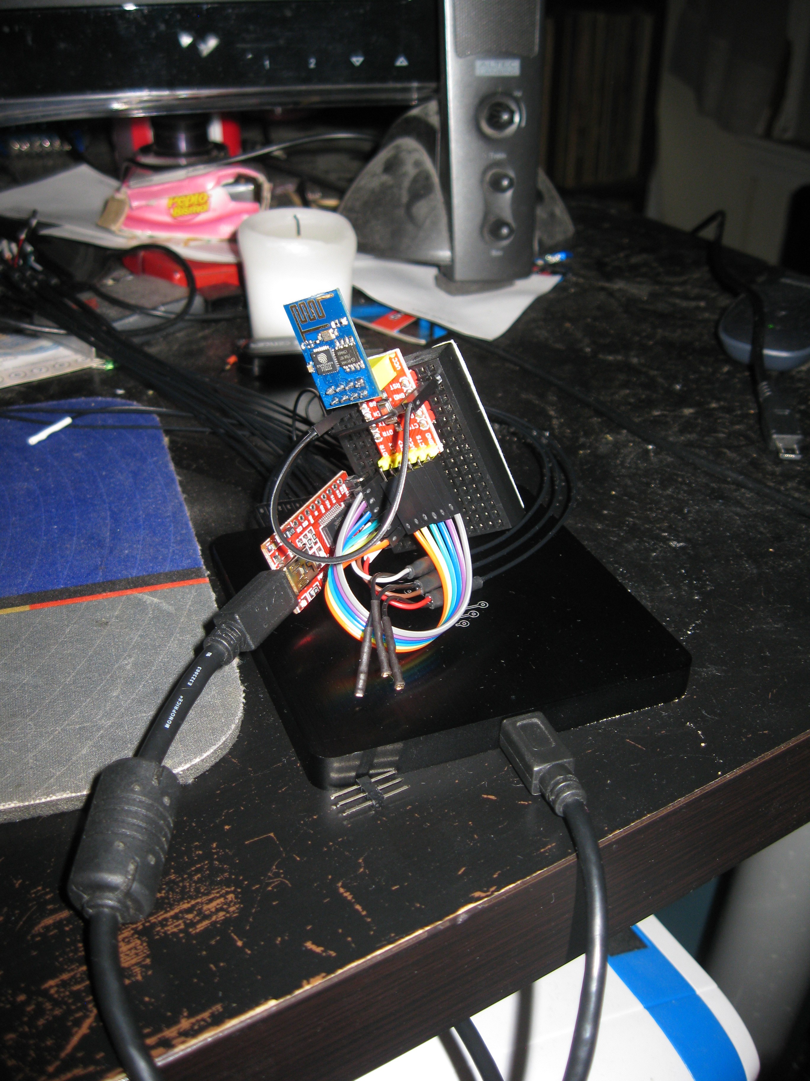
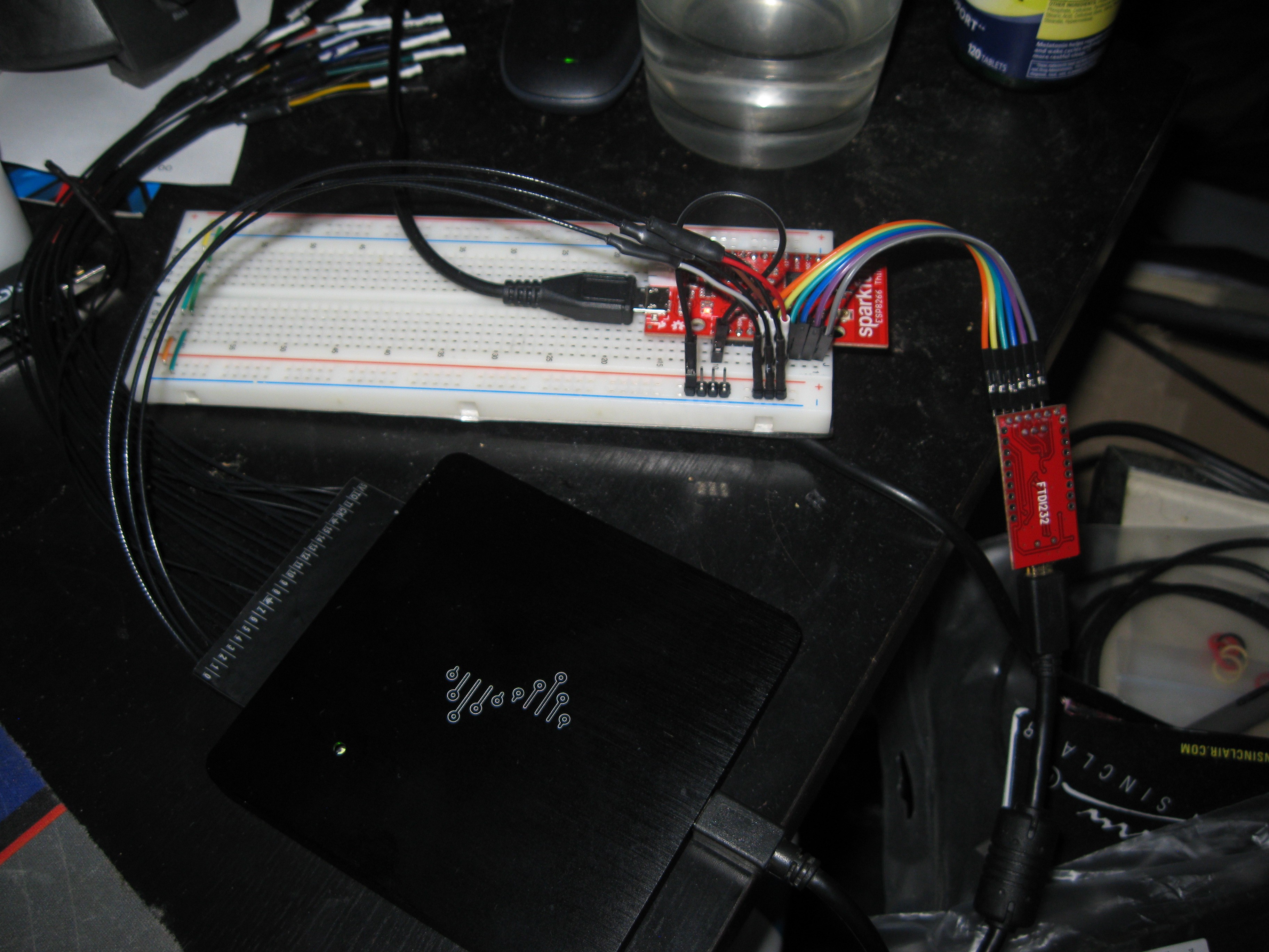
As for embedded work I have been experimenting with the ESP8266 modules I have and the Arduino IDE. The reason for using the IDE is that its a simple way to see if the ESP modules I purchased are non-counterfeit or just work like they are supposed to. I also messed around with my Sparkfun ESP8266-Thing but did not get it to program with the IDE. I explored it with a logic analyzer and discovered that the chip isn't talking back but thats as far as I got with it. Here are some pictures of the two test setups I'm working with:
Standard ESP-02 module, hooked up to an FTDI breakout that can do 3v3 and 5v power. Pictured is the logic analyzer wired up to monitor the RX/TX lines. I was looking to record an entire programming sequence and see how it compared to the the sparkfun module's response.
![]()
Sparfun board setup, I really hope I figure out whats wrong with it, I think I might have bricked it. Though I have to say this logic analyzer has been super useful !
![]()
My next plan for the ESP hardware is to setup the bare metal GCC based toolchain under linux and perform tests with that. I will be using the standard toolchain for compiling the Bowler MCU server for the ESP chip. After I have the ESP working with its toolchain I'm turning my attention back towards the FreeScale hardware, the plan is to setup a terminal build script under linux using the ARM GNU toolchain so that I can work independently of the Kinetis IDE. Stay tuned for more interesting updates to come, next week I am soldering all the PCBs together by hand, I promise there will be lots of pictures!!!!
-
NFT Grow Unit Progress
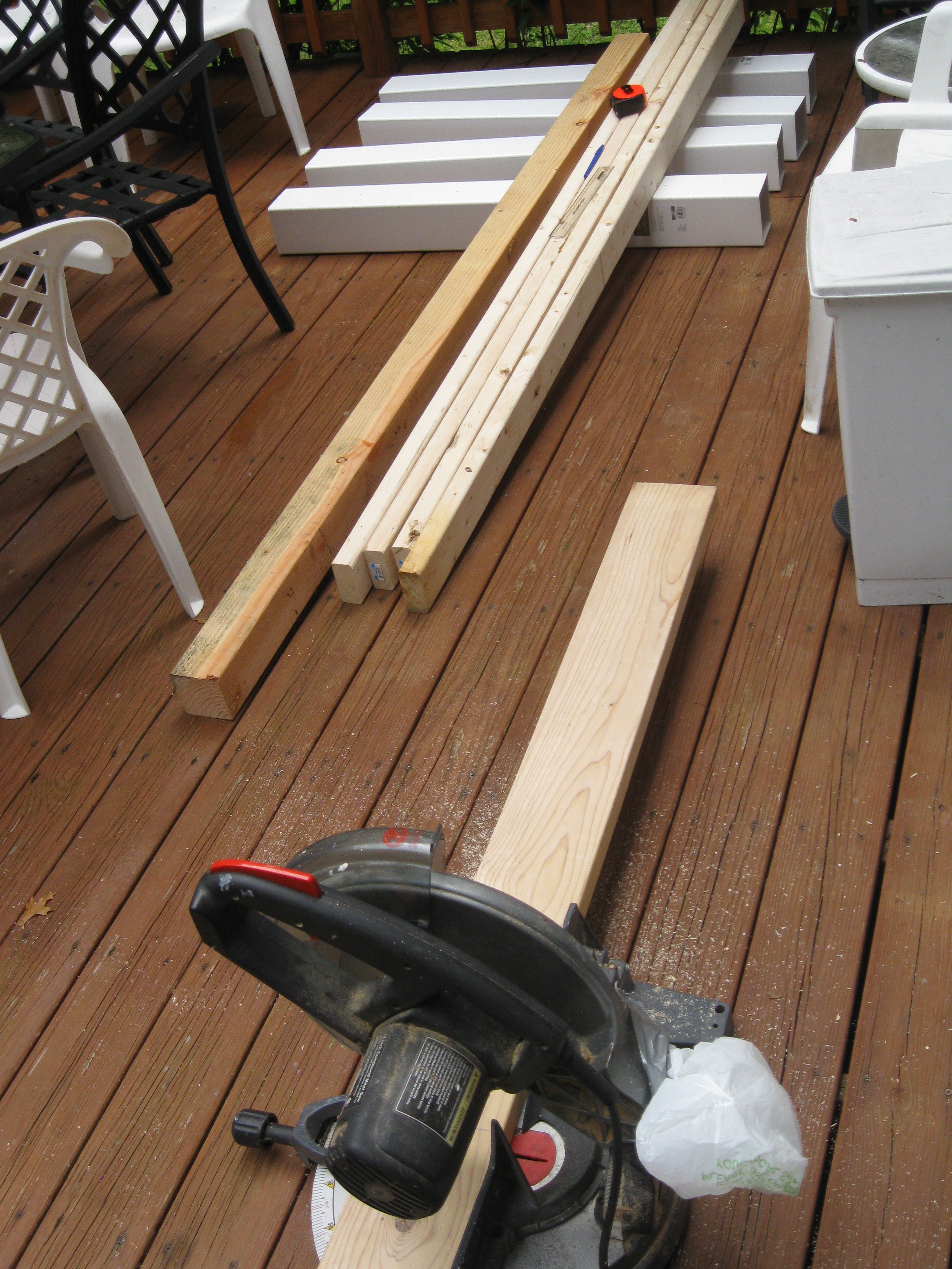
07/20/2015 at 03:13 • 0 commentsLast week I did a lot more work on the NFT grow unit the HydroPWNics control system will be deployed on. I finally decided on a simple design to hold up the 4 cut piece of fence posts holding the plants. I choose to cut the two by fours into two pieces one larger than they other. I used all these piece to make a simple box frame and added boards on top to strengthen and support it further. Its hard to describe with words so I have included a bunch of pictures of what I have done so far:
Materials laid out being measured and cut
![]()
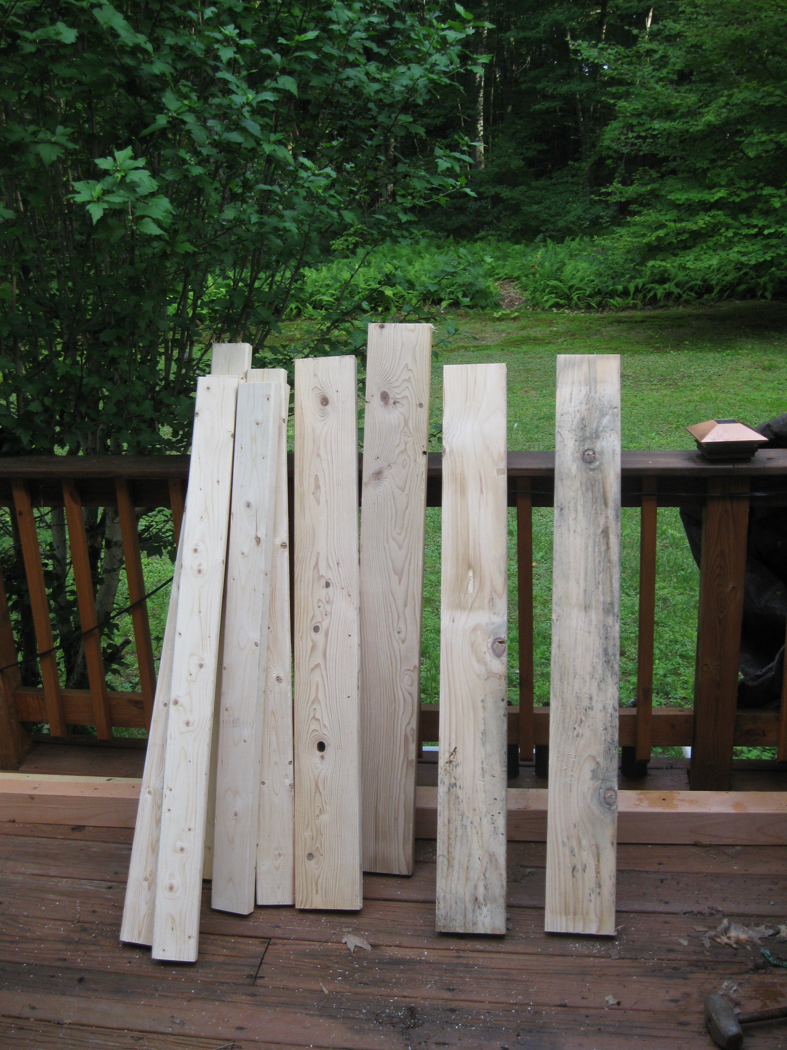
Wood all cut to length, time to drill pilot holes and screw it all together:
![]()
Just placing it together to see how it fits and see how well the cuts came out. The cuts were spot on, and everything slid together without any real big gaps between wood. You can see how the pieces were cut purposely uneven (like how I mentioned before) so that they fit together neatly at each corner.
![]()
Closer look at the at the construction
![]()
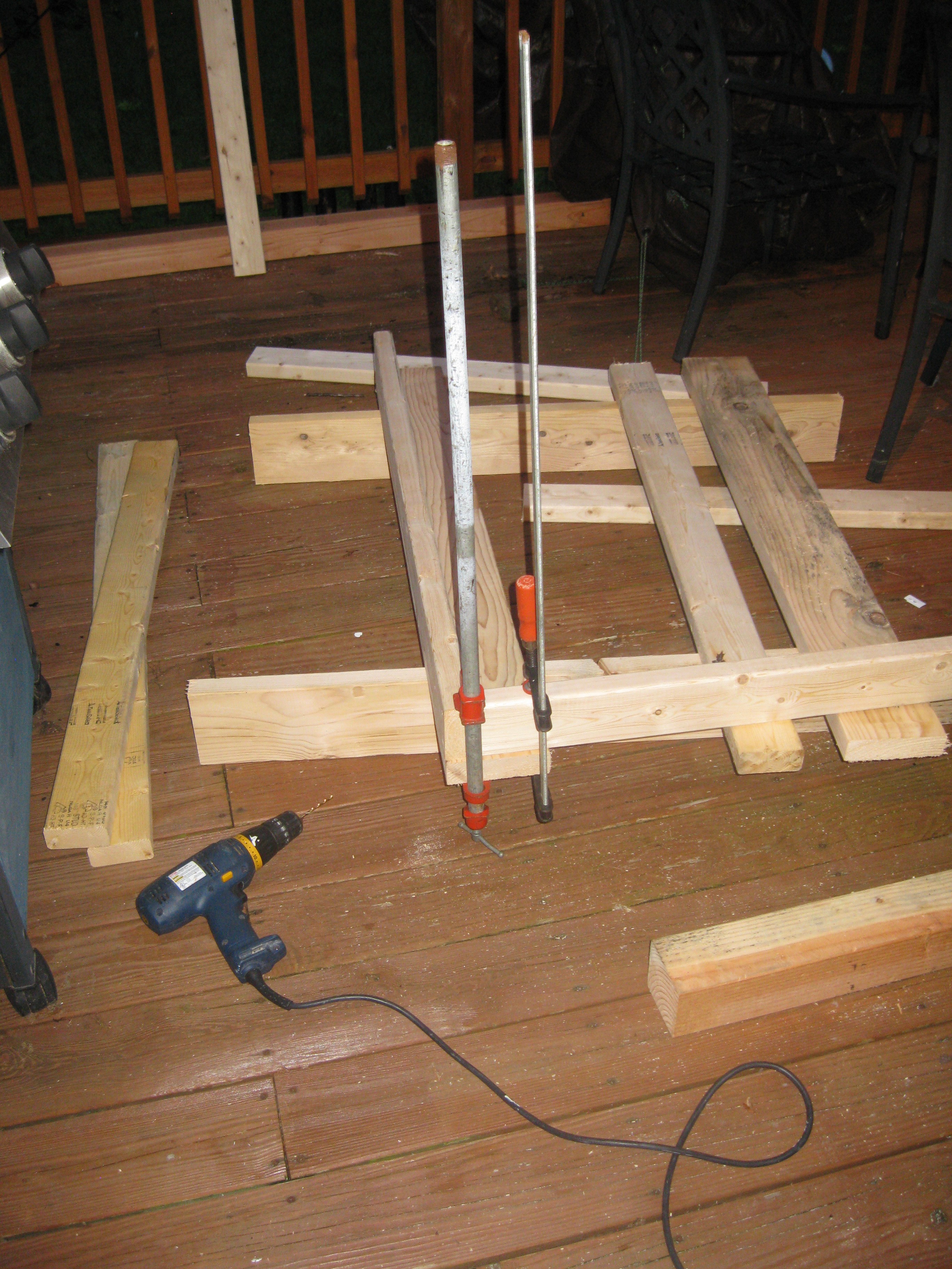
Its much darker out because it took me a while to find some clamps around the house. I clamped each joint together, when I drilled the pilot holes and left them clamped when I added the screws. It took much longer to clamp and drill pilot holes but in the end I didn't get any cracks in the wood and everything went together rather smoothly.
![]()
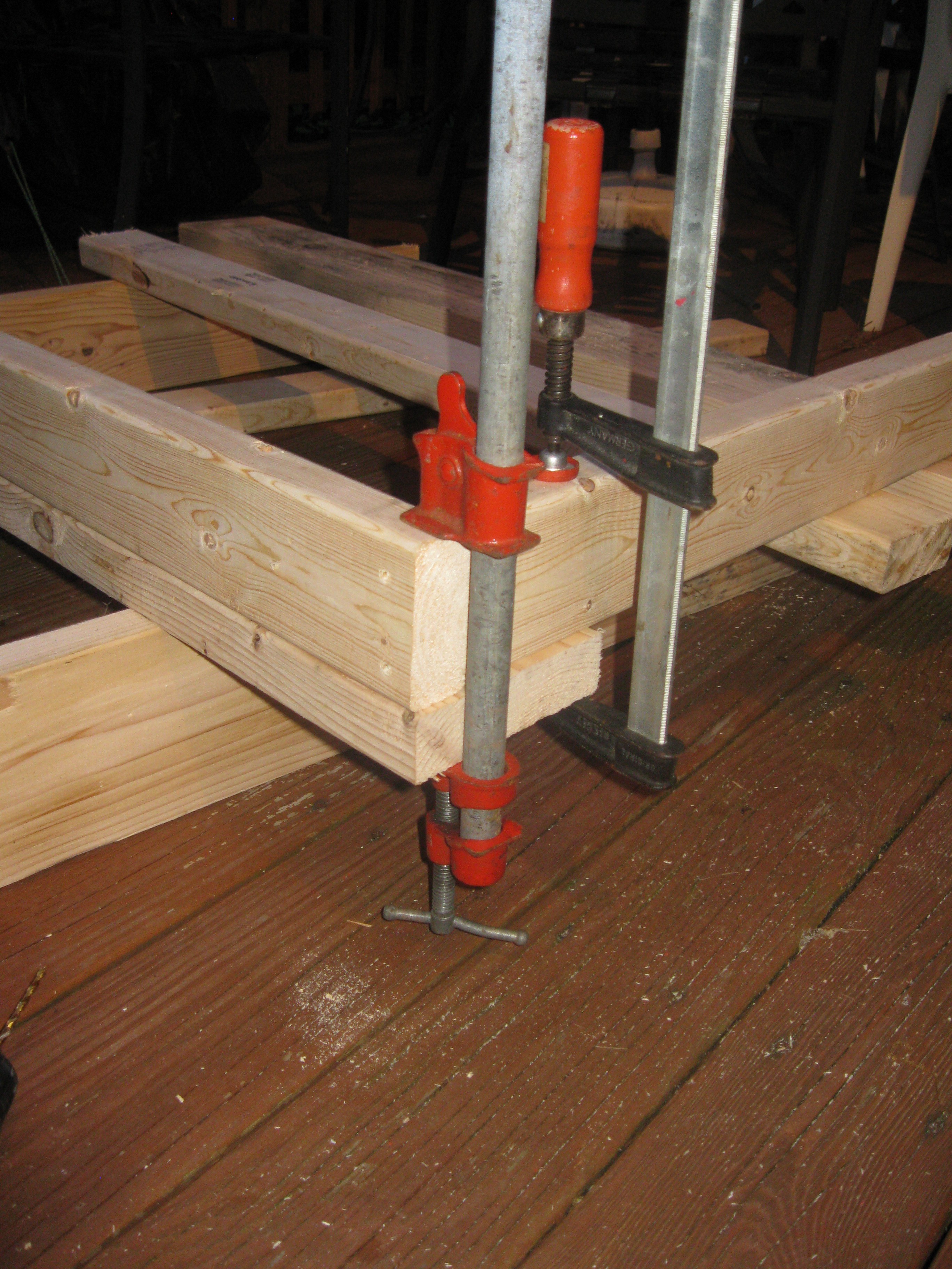
Closer look at the clamp placement and placement of the wood. I forgot to take pictures earlier but what I did firs was take the longer lengths of two by four for the frame and bolted them to the top planks at the end, which are also the same length. I did that first to make it easier to clamp, drill, and screw each corner of the frame.
![]()
The frame after the first day of work. The middle two by fours are screwed in from the top and side, so they are held in place rather well. One got attached crooked and it makes things look weird but I plan to fix it later before I paint the frame.
![]()
Stay tuned for another update on the frame as well as the rest of the project either later tonight or tomorrow. This post is for last week's work and I just forgot to make a post. I hope to have some more to show from this past week, so stay tuned!!!
-
PCBs Here, Code Moved, and More!!!
07/10/2015 at 07:23 • 0 commentsGot a pretty big update this evening. First off the HydroPWNics project was selected for a few awards this week. During this week hackaday announced the projects that won the sponsor list prizes. I am proud and happy to say HydroPWNics was selected for all four sponsor prices, Texas Instruments, Microchip, FreeScale, and Atmel. I'd like to thank Hackaday and the Sponsors for the excellent prizes!!! Its always nice to be featured in he spotlight of this fantastic community ! Well anyway on with the really fun things!
Last evening I decided to move all the code over to a dedicated github organization called HydroPWNics (surprising I know). Each component of the software and hardware have their own repositories. Dedicated repos for firmwares, hardware source, application software, webpage, and API. All the source code and repositories can be found here: https://github.com/HydroPWNics
Earlier this week my PCBs arrived in the mail. As per usual OSHPark did a great job with the board, the quality is pretty great from hand inspection. Now that PCBs are in I should be ordering components soon but I've yet to do an inventory on the components I have, I'll probably have that done over the weekend and adjust my digikey order to save some bucks. Next off will be assembly, I plan to populate the boards at the local hackerspace Technocopia with the help of some friends. I think I can get all the hardware assmbled in one day at the space and estimate a week of debugging before finding all flaws in the boards.
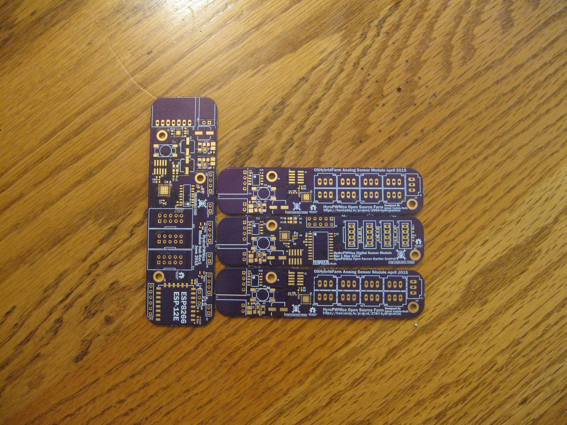
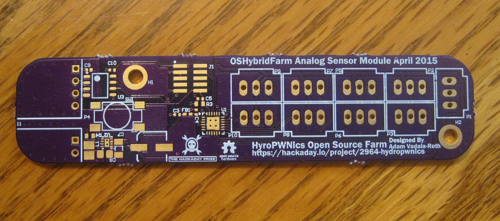
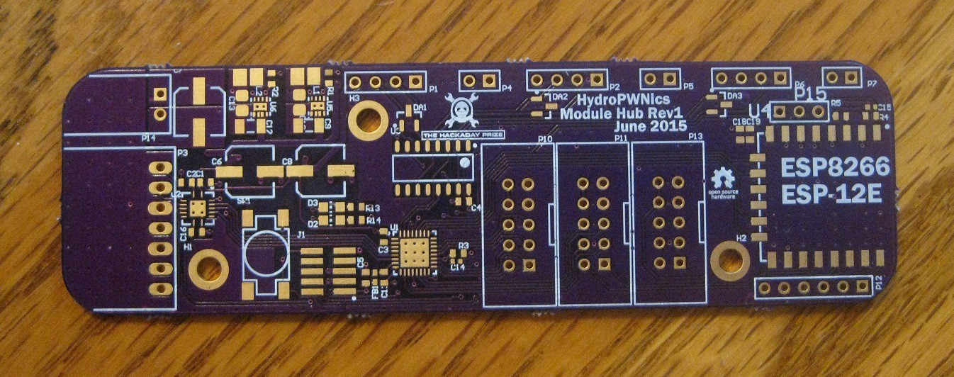
The PCBs:
How the modules fit together with the Module Hub:![]()
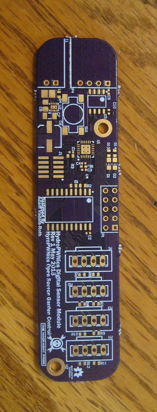
Digital Sensor Module up close![]()
![]()
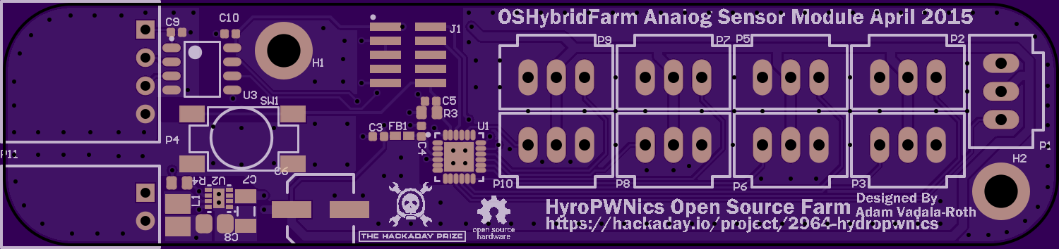
Analog Sensor Module
Module Hub![]()
![]()
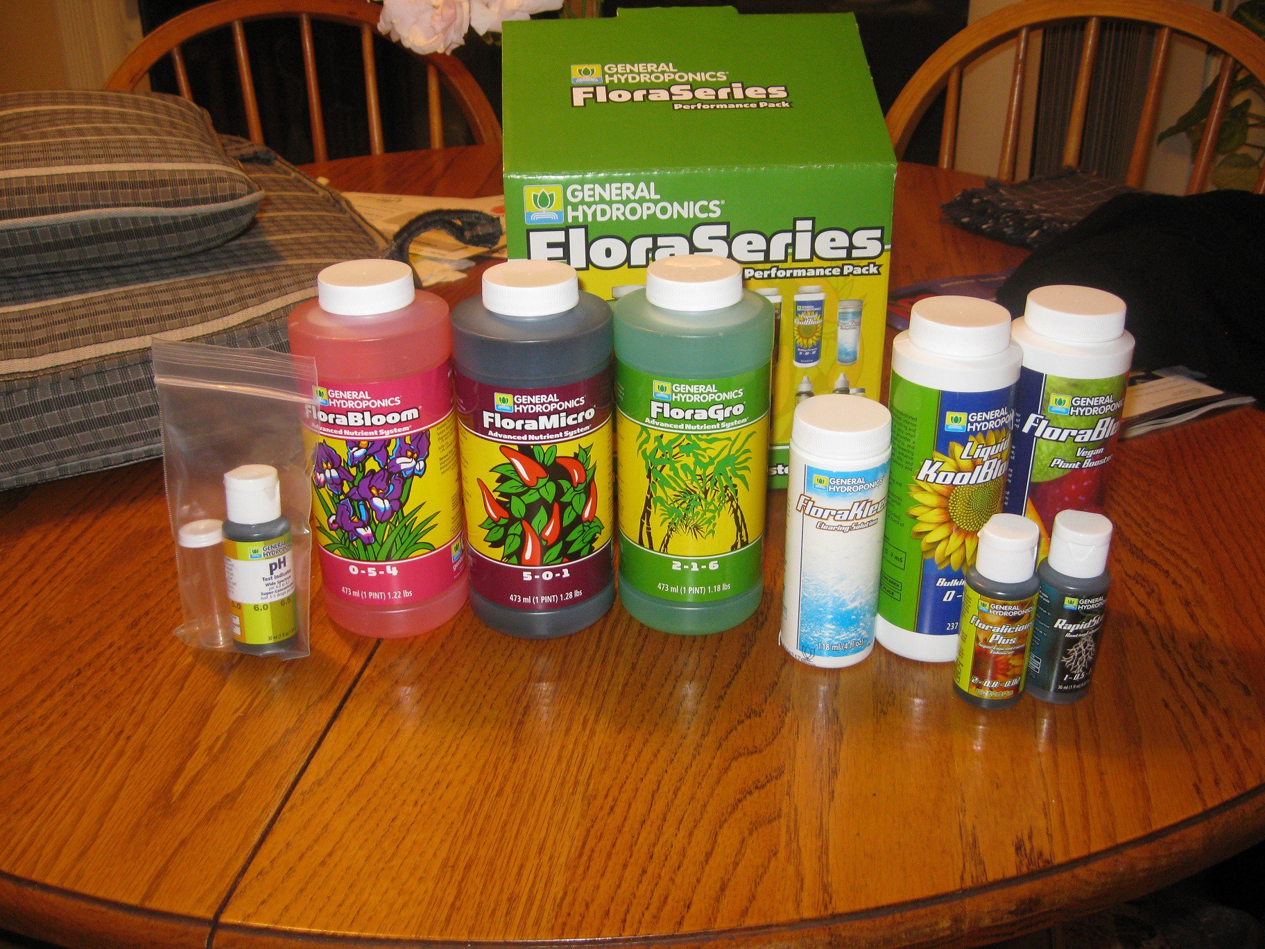
On another note, about 3 weeks back I won a trivia contest that General Hydroponics was holding on their facebook page. They posted a picture of a moth and I correctly identified it to win a GH Performance pack. This kit includes more of the nutrients and pH management solution that I already have but also includes a bunch of other supplements and boosters for various plant stages.![]() Stay tuned for more updates over the weekend!
Stay tuned for more updates over the weekend! -
Update: started embedded sofware
07/02/2015 at 04:36 • 0 commentsOver the last two days I worked on the embedded software for the HydroPWNics Hardware. As mentioned before the hardware is based on FreeScale ARM Cortex M0+ microcontrollers, the Kinetis MKL05Z16VFK4 and MKV10Z16VFM7. To develop and program for these FreeScale MCUs I am using the new FreeScale IDE Kinetis Design Studio. I worked on developing basic hardware libraries to control the hardware peripherals on the microcontrollers, this is he first step before writing an application specific firmware. The process this time around was very different from what I'm used to, it will all be explained in the rest of the post!
Kinetis Studio
![]()
Kinetis Design Studio is an eclipse based IDE, (its the expected IDE really, Ti has their own, NXP has their own, etc) it combines the standard Eclipse C/C++ layout with a an array of tools/plugins specific for FreeScale Kinetis ARM Cortex development. KDS is a free tool and uses the GNU ARM GCC toolchain for building projects. In addition to the standard features of the Eclipse-ARM-Cortex-IDE (my generic term for these sorts of IDEs they are mostlty the same) KDS has a neat tool called Processor Expert. Processor Expert is a nifty graphical interface with lots of menu options and a physical representation of the MCU you are using. With Processor Expert you can configure the microcontroller and code libraries for ther peripherals and pins you are using in your happlication with simple context menus. After you configure everything how you like for your application Processor Expert will auto generate logical device drivers for all the hardware peripherals/GPIO you chose in the in configuration!
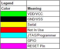
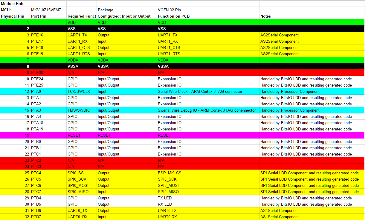
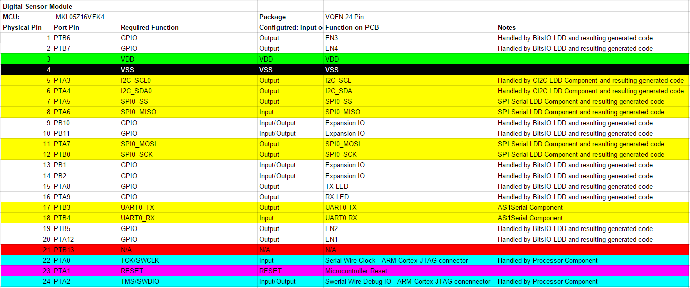
After playing around with Kinetis Design Studio for a while and Processor Expert, I figured out how to use them correctly and set out to created custom libraries for the HydroPWNics hardware. I started by making charts of the pinouts of the microcontrollers on the PCBs in google docs spreadsheets. The chart shows the physical pin, port name, the function the pin needs to be set to, the function on the PCB, and a note (typically which Kinetis component being used for code generation).For easy viewing I screencapped the documents and the legend below:
Pinout Map Legend
![]()
Module Hub Pinout Mapping
![]()
Digital Sensor Module Pinout Mapping
![]()
Analog Sensor Module Pinout Mapping
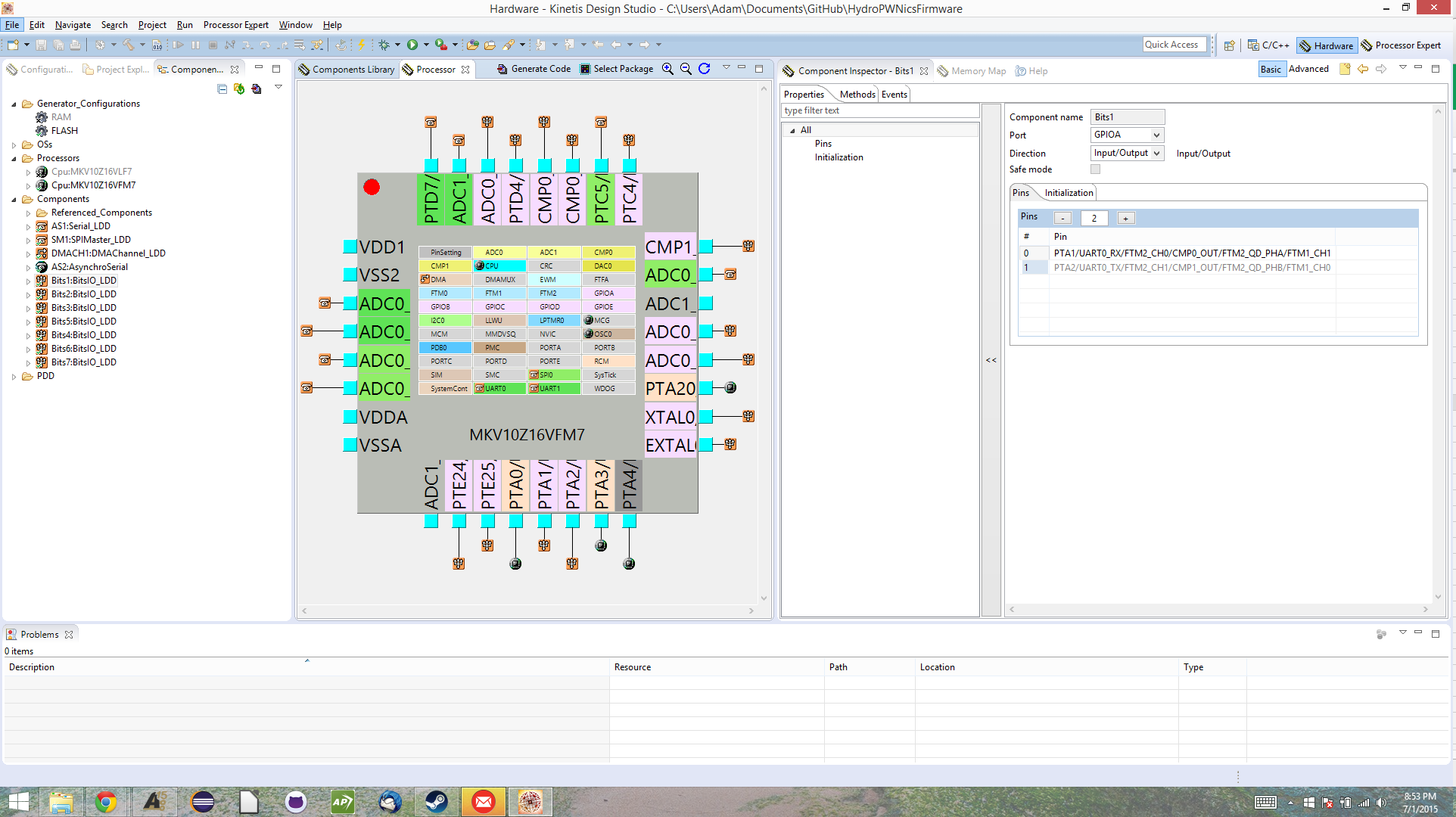
MKL05 Processor Expert : This is the Processor Expert View in Kinetis Design Studio, this is for the MKL05 series MCU being used on the sensor modules, you can see that the graphic is the 24 VQFN package being used on the sensor module boards.
![]()
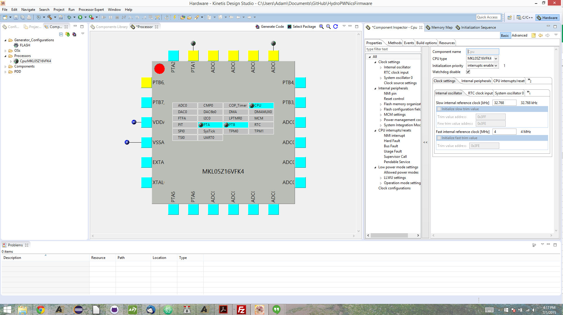
MKV10 Processor Expert: Processor Expert view for the MKV10 series MCU being used on the Module hub. This screenshot shows a bit more, it was taken after I finished the configuration. I didn't say much before but configuration is carried out by selecting "Components" that represent a type of code that can be generated for a given function. The options are usually a logical device driver (simple register level driver code), basic init code (just configuring peripheral registers and nothing else), or a high level application device driver. Once components are chosen they are added to the component list for the project. Components after being added need to be configured, this usually amounts to baudrates or clock divisers for serial or timers and pin mapping for peripherals. Configuration is simple and Processor Expert notifies you of conflicts if component configurations are using the same resources or pins. Once configuration is complete code can be generated with the click of a button.
![]()
I mentioned earlier how this process has been different than I'm used to, well traditionally a library would have to be written at the register level, by digging through the datasheet. Sometimes a manufacture has a prewritten library that just needs to be compiled but this time there was the Processor Expert feature. I guess this is the new way of doing things and its kind of awesome really, this feature has saved me a lot of time and I look forward to spending more time on the application code than hardware drivers!
The software sources for all the firmware can be found in the HydroPWNicsFirmware github repository here: https://github.com/adamjvr/HydroPWNicsFirmware This is only a start so far, a lot has to be done in the coming weeks but I feel that what got done for this post is a good start given that I don't have any hardware in hand yet. PCBs should be coming in the next few days and I will be ordering components and development hardware soon, stay tuned for more to follow on the embedded software and more of HydroPWNics!
-
Java Dev Day Update!
06/29/2015 at 03:51 • 0 commentsSo today I spent some time working on the higher level software for the system. I'd say good chunk got done too but there is still plenty to go. I started with the Java software because for the most part the system's layout and how all the subsystems interact with eachother is basically decided (see previous diagram). Most of the code written today pertains to the data object and how the data of each plant and garden as a whole will be represented and managed inside the Java program. Code from today is found at the following repo: https://github.com/adamjvr/HydroPWNicsAPI
The data structure for the the garden is a sort of nested data structure. The Garden as a whole is represented by a Garden object, the Garden object is made up of PlantRow objects. PlantRow represents a row of plants in the system, PlantRowm has a fixed size set during instantiation. The PlantRow object holds up to the set max amount of Plant objects in an ArrayList. The objects represent the different physical components of the grow units, the plants and the fence post row units they grow in. The Plant object represents a plant, Plant objects are contained by PlantRow objects. A Plant object contains an arraylist of all data samples (timestamped) take during the plants lifetime in addition to characteristics such as name and type. So thats the general overview of how the data of the garden will be handled internal.
Some Code Snippets of the Data Objects can be found below, keep in mind these are rough and very bleeding edge lol
Plant Object
package com.DataTypes.hydroPWNicsAPI.github.io;

import java.sql.Timestamp;
import java.util.ArrayList;
import java.util.Iterator;
public class Plant {
	/**
	 * plantDataSamples : an ArrayList of type PlantData containing all the data
	 * samples on a given plant complete with timestamp
	 */
	ArrayList<PlantData> plantDataSamples = new ArrayList<PlantData>();

	/**
	 * plantDataSamplesIterator an Iterator of Type PlantData for cycling
	 * through the arraylist of containing all plant data samples
	 */
	Iterator<PlantData> plantDataSamplesIterator = plantDataSamples.iterator();

	/**
	 * datPlanted : a timestamp oject denoting the time the plant was added to
	 * the system
	 */
	Timestamp datePlanted = new Timestamp(0);

	/**
	 * PlantTyep : a string of the plant type, e.g Tomato, or Pepper etc
	 */
	String PlantType = "N/A";

	/**
	 * plnt_stage : an enum denoting the plants growth stage, Seedling, sprout,
	 * vegetive, flowering and fruiting.
	 */
	PlantStage plnt_stage = null;

	/**
	 * Instantiation constructor, acceps a date of planting, string for type
	 */
	public Plant(Timestamp date, String type, PlantStage pstage) {
		datePlanted = date;
		PlantType = type;
		plnt_stage = pstage;
	}


	/**
	 * Returns plant data on a given day/time
	 *
	 * @param desired_date
	 *            accepts a timstamp object representing the desired date
	 * @return returns a PlantData object containing all the plant data on the
	 *         specified date.
	 */
	public PlantData getPlantDataOnDate(Timestamp desired_date) {
		PlantData dd_data = new PlantData();
		Timestamp iterator_time = new Timestamp(0);
		while (plantDataSamplesIterator.hasNext()) {
			dd_data = plantDataSamplesIterator.next();
			iterator_time = dd_data.getSmplDate();

			if (iterator_time.equals(desired_date)) {
				return dd_data;
			}// end if

		}// end while
		return null;
	}// end funct

	/**
	 *
	 * @return
	 */
	public int getDays() {
		return 0;
	}

	/**
	 *
	 * @return
	 */
	public int getWeeks() {
		return 0;
	}
}
PlantData Object
package com.DataTypes.hydroPWNicsAPI.github.io;

import java.sql.Timestamp;

public class PlantData {

	/**
	 * plant_humidity Humidity within the vicinity of the plant
	 */
	double plant_humidity = 0.0;
	/**
	 * plant_temp the temperature within the vicinity of the plant
	 */
	double plant_temp = 0.0;
	/**
	 * smpl_waterData : the waterData at the time of that the sample of plant
	 * data is taking place
	 */
	WaterData smpl_waterData = new WaterData();

	/**
	 * lght_tmp : an enum pertaining to the type of light conditions the plant
	 * is under at the time of the plant data sample taking place
	 */
	LightTemp lght_tmp = null;
	/**
	 * type : an enum pertainting to the type of garden the plant is in,
	 * hydroponic, soil, or soiless
	 */
	GardenType type = null;
	/**
	 * smplDate : a Timestamp object containting the date and time the sample of
	 * plant data occurred.
	 */
	Timestamp smplDate = new Timestamp(0);

	/**
	 * Main constructor used for full instantiation of PlantData Object
	 *
	 * @param iplant_humidity
	 *            Humidity around the plant at time of sample
	 * @param iplant_temp
	 *            Temperature around the plant at time of sample
	 * @param ismpl_waterData
	 *            Water datagram at the time of sample
	 * @param itype
	 *            Plant type, hydroponic, soil, or soiless pertains to garden
	 *            growth type
	 */
	public PlantData(double iplant_humidity, double iplant_temp,
			WaterData ismpl_waterData, GardenType itype, LightTemp ilght_tmp,
			Timestamp idate) {
		plant_humidity = iplant_humidity;
		plant_temp = iplant_temp;
		smpl_waterData = ismpl_waterData;
		type = itype;
		lght_tmp = ilght_tmp;
		smplDate = idate;
	}

	/**
	 * default constructor defaults to hydroponic garden designation all other
	 * datatypes default to their constructor default in this case
	 */
	public PlantData() {
		type = GardenType.HYDRO;
	}


	/**
	 * getPlant_humidity : returns the plants humidity
	 *
	 * @return returns type double, member variable pertaining to humidity of
	 *         plant at time of sample
	 */
	public double getPlant_humidity() {
		return plant_humidity;
	}

	/**
	 *
	 * @return
	 */
	public double getPlant_temp() {
		return plant_temp;
	}

	/**
	 *
	 * @return
	 */
	public WaterData getSmpl_waterData() {
		return smpl_waterData;
	}

	/**
	 *
	 * @return
	 */
	public GardenType getType() {
		return type;
	}

	/**
	 *
	 * @param type
	 */
	public void setType(GardenType type) {
		this.type = type;
	}

	/**
	 *
	 * @return
	 */
	public Timestamp getSmplDate() {
		return smplDate;
	}

}
PlantRow Object
package com.DataTypes.hydroPWNicsAPI.github.io;

import java.util.ArrayList;
import java.util.Iterator;

public class PlantRow {
	int num_plants = 0;
	int max_plant_num = 4;
	ArrayList<Plant> PlantsInRow = new ArrayList<Plant>();
	Iterator<Plant> IPlantsInRowIterator = PlantsInRow.iterator();

	/**
	 * Main Constructor
	 *
	 * @param iPlantsInRow
	 */
	public PlantRow(ArrayList<Plant> iPlantsInRow) {
		PlantsInRow = iPlantsInRow;
		num_plants = iPlantsInRow.size();
	}

	/**
	 *
	 * @return
	 */
	public int getNumberOfPlants() {
		return num_plants;
	}

	/**
	 *
	 * @return
	 */
	public Plant getPlant(int list_index) {
		return PlantsInRow.get(list_index);
	}

	/**
	 *
	 * @param newPlant
	 */
	public void addPlantToRow(Plant newPlant) {
		if (PlantsInRow.size() < max_plant_num) {
			PlantsInRow.add(newPlant);
		}
	}

}
Garden Object
package com.DataTypes.hydroPWNicsAPI.github.io;

import java.util.ArrayList;
import java.util.Iterator;

public class Garden {
	ArrayList<PlantRow> GardenRows = new ArrayList<PlantRow>();
	Iterator<PlantRow> IGardenRowsIterator = GardenRows.iterator();
	int GardenRowCount = 0;
	int MaxGardenRowSize = 0;
	int PlantRowSize = 0;
	int GardenSize = 0;

	public void addRowToGarden(PlantRow rowToAdd){
		if(GardenRows.size()<MaxGardenRowSize){
			GardenRows.add(rowToAdd);
		}
	}

	public void AddPlantToGarden(PlantRow whchRow, int plantRowNum){

	}


	public void removePlantFromGarden(PlantRow whchRow, int plantRowNum){

	}


}
On another note in regards to the Java side of things, I did also begin the Java objects representing the hardware. This component of the system is a bit more complex than I anticipated so I didn't get much done in one sitting. I need to read up more on the custom Bowler device documentation from Neuron Robotics before I move ahead anymore with this code.
For transmitting the data to the cloud, I have decided to use JSON packets and the google Gson Java JSON library. With the Gson library I can easily serialize the datatype objects into JSON strings and push them to the cloud. The reason to use JSON is that its simple, readable, and well used. JSON use is definitely the newest development in the project so I don't have much else to say on the subject, so stay tuned for new updates!!!!
-
Project Components
06/28/2015 at 06:24 • 0 commentsSo given that this project has been added to so many project parts lists I feel that it deserves an explanation particularly because two of the lists don't seem to make sense right away.........
So I'll start with the custom hardware. HydroPWNics so far had three unique pieces of electrical hardware designed to date, the Module Hub, the Analog Sensor Module, and the Digital Sensor Module. This board have qualified HydroPWNics to be listed in the Texas Instruments and FreeScale lists. First off the FreeScale List: Each of these boards is powered by a FreeScale ARM Cortex M0+. All Modules use the FreeScale MKL05Z16VFK4 48MHZ ARM Cortex M0+, this controller was chosen for cost effectiveness, performance, and overall simplicity. It's a rather simple controller using not too many external parts and having one of every peripheral. Another note is that it can be programmed with the freedom board. Modules for functions will also use the same MCU, I only say this now because only the sensing modules have been designed/fabbed. The Module Hub is using the FreeScale MKV10Z16VFM7 75MHZ ARM Cortex M0+, this controller was chosen for cost effectiveness and impressive performance. The reason for the higher clock speed is that the module hub has to perform wifi coms and control three modules at the same time.
For Texas Instrument parts all the boards use TPS series DCDC converters, I've been wanting to try these regulators out for a while and felt this was a good project to do so. The TPS62162 is a fixed 3.3v DCDC converter, I chose it because its got decent efficiency and it results in a very small footprint. The TPS62163 is a fixed 5v DCDC converter, I chose it for the same reasons as the TPS62162 as they use the same supporting passives and have the same route. These DCDC regulators also can support 1A of current at their respective voltages ensuring that there will be plenty of power for everything. As a general rule I tend to use Ti power parts, there are plenty of options a lot of them cheap :) .
Now for the interesting. The project is also listed in the microchip and Atmel lists. Looking at the projects component list this may seem puzzling. The explanation is that a component of this project contains those parts. The DyIO has both a microchip PIC32 and Atmel Atmega in it, hence qualifying this project for those lists. It puzzled me at first but then I thought about it. Anways who knows if I will add an Arduino or two or add my ChipKit into the mix down the road?Stay tuned for more project updates and edits to the documentation!!!!!!!!!
-
Description update and More
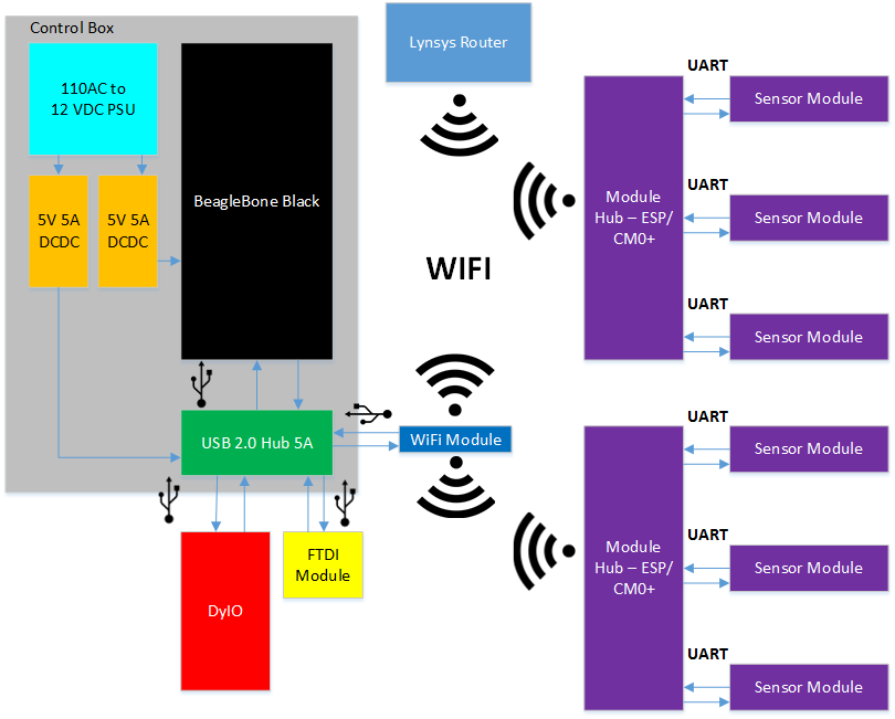
06/28/2015 at 06:06 • 0 commentsSo over the last day or two I have been slowly retooling the description of the project, I'm still editing it and what not but you can check it out here: https://hackaday.io/post/15141 There have been some changes to the project since the original description was written. originally the DyIO was going to be the main controller, a Raspberry Pi 2 was going to be used in the control box, and the web page was going to be java based.
The new system is using a Beaglebone Black for the control box, the custom HydroPWNics hardware I've been blogging about all spring, a dedicated WIFi network via router, and the web page is going to be hosted on an actual web server. The new system has the Beaglebone black running the java application controlling the garden and pushing the data pulled from the Module Hubs to a web server. This system will allow me to publicly host the sight and handle a decent amount of traffic so I can show the plant data of the NFT system I'm building. A benefit to this new system is that the there won't be any need for a web page API using Apache strut since the web page will be a standard HTML5 page receiving data over a secure socket. Below is a diagram of the new system, also available in the project description
![]()
-
PCBs Ordered! and Part BOMs Made!
06/24/2015 at 07:13 • 0 commentsOver the weekend I ordered the first round of PCBs for HydroPWNics. I went with OSHPark because they make decent quality boards cheap and fast. PCBs for the Module Hub, Analog Sensor Module, and Digital Sensor Module will be at my doorstep in about another week. The cost of the PCBs didn't change since my last post on the subject (see the PCB cost estimate log) but have undergone many updates for fabrication and electrical integrity. Most of the tweaking was running design rule checks on the PCBs and correcting the resulting errors.
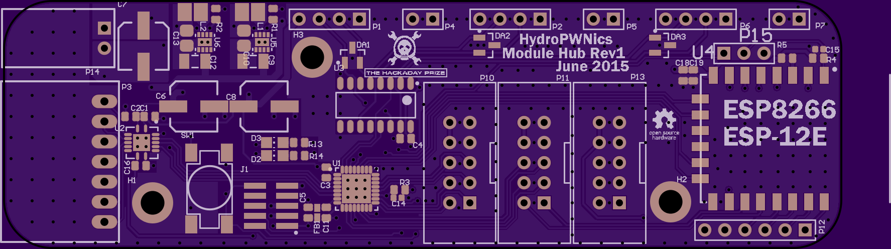
Renders of the PCBs sent to the fab, these are the Rev1s!
Module Hub:
![]()
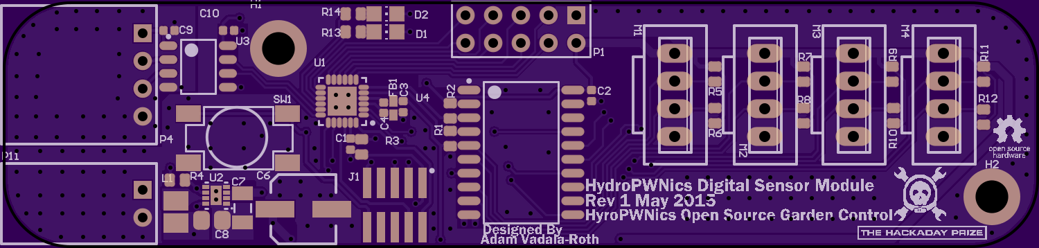
Digital Sensor Module
![]()
Analog Sensor Module
![]()
As for the part BOMs I made a few. There are two kinds of BOMs for each board, a build BOM, and a order BOM. The build BOM is used for assembly purposes, it is to be read like instructions, each step being a designator correlating to a component. The order BOM is for ordering a set of parts for a given board, it organizes the components by quantity for simple ordering from electronics suppliers (I use digikey and Mouser).
Module BOM:
Symbol Value Package Quantity Digikey Part Number Manufacturer Part Number Price Quantity Price Build 3 Price Build 10 Price Build 25 Price C1, C2, C3, C4, C16, C18 100nF C0603 6 399-5089-1-ND C0603C104K5RACTU $0.10 $0.60 $1.80 $6.00 $15.00 C5, C11, C19 10uF 6.3VDC C0603 3 445-11185-1-ND C1608JB0J106K080AB $0.37 $1.11 $3.33 $11.10 $27.75 C6, C7, C8 100uF EEE-1VA101XP 3 PCE3951CT-ND EEE-1VA101XP $0.63 $1.89 $5.67 $18.90 $47.25 C9, C12 10uF 50V C1206 2 1276-2876-1-ND CL31A106KBHNNNE $0.65 $1.30 $3.90 $13.00 $32.50 C10, C13 22uF C0805 2 1276-2907-1-ND CL21A226KQQNNNE $0.56 $1.12 $3.36 $11.20 $28.00 C14, C15 100nF C0402 2 490-3261-1-ND GRM155R71C104KA88D $0.10 $0.20 $0.60 $2.00 $5.00 D2, D3 5988140107F LED2012120 2 350-2041-1-ND 5988140107F $0.45 $0.90 $2.70 $9.00 $22.50 DA1, DA2, DA3 PESD3V3L2BT SOT95P230X110-3N 3 568-4046-1-ND PESD3V3L2BT $0.58 $1.74 $5.22 $17.40 $43.50 FB1 BLM15HG601SN1D BLM15HG601SN1D 1 490-3998-1-ND BLM15HG601SN1D $0.23 $0.23 $0.69 $2.30 $5.75 0 0 0 0 J1 FTSH-105-XX-X-DV 1 S9013E-05-ND ARM Cortex JTAG-DEBUG Header $1.30 $1.30 $3.90 $13.00 $32.50 L1, L2 2.2uH VLS252012T-2R2M1R3 2 445-3670-1-ND VLS252012T-2R2M1R3 $0.81 $1.62 $4.86 $16.20 $40.50 P1, P2, P6 HDR1X4 3 S5440-ND PPTC041LGBN-RC $0.73 $2.19 $6.57 $21.90 $54.75 P3 705530041 1 WM4929-ND 705530041 $1.94 $1.94 $5.82 $19.40 $48.50 P4, P5, P7 HDR1X2 3 S5438-ND PPTC021LGBN-RC $0.57 $1.71 $5.13 $17.10 $42.75 P10, P11, P13 3020-10-0100-00 3 1175-1609-ND 3020-10-0100-00 $0.48 $1.44 $4.32 $14.40 $36.00 P12 HDR1X6 1 Header 6 0 0 0 0 P14 705530001 1 WM4900-ND 705530001 $0.74 $0.74 $2.22 $7.40 $18.50 P15 HDR1X3 1 Header 3 0 0 0 0 R1, R2 100K R0603 2 311-100KHRCT-ND RC0603FR-07100KL $0.10 $0.20 $0.60 $2.00 $5.00 R3, R4, R5, R13, R14 1K R0603 5 P1.00KHCT-ND ERJ-3EKF1001V $0.10 $0.50 $1.50 $5.00 $12.50 SW1 TL3301AF160QG 1 EG2526CT-ND TL3301AF160QG $0.43 $0.43 $1.29 $4.30 $10.75 U1 MKV10Z16VFM7 1 MKV10Z16VFM7-ND MKV10Z16VFM7 $2.50 $2.50 $7.50 $25.00 $62.50 U2 RGY (S-PVQFN-N14) 1 296-20698-1-ND TXS0104E $2.01 $2.01 $6.03 $20.10 $50.25 U3 74HC4052 1 568-1456-1-ND 74HC4052 $0.56 $0.56 $1.68 $5.60 $14.00 U4 ESP8266 ESP-12E 1 ESP-12 0 0 0 0 U5, U6 DSG8-1600X900TP 1 296-29897-1-ND TPS62162DSG $2.62 $2.62 $7.86 $26.20 $65.50 U6 DSG8-1600X900TP 1 296-29898-1-ND TPS62163DSGR $2.30 $2.30 $6.90 $23.00 $57.50 $19.14 $57.42 $191.40 $478.50 Digital Sensor Module BOM
Symbol Value Package Quantity Digikey Part Number Manufacturer Part Number Price Quantity Price Build 3 Price Build 10 Price Build 25 Price Comment C1, C2, C3, C4, C9, C10 100nF C0402 6 490-3261-1-ND GRM155R71C104KA88D $0.10 $0.60 $1.80 $6.00 $15.00 C6 100uF EEE-1VA101XP 1 PCE3951CT-ND EEE-1VA101XP $0.63 $0.63 $1.89 $6.30 $15.75 C7 10uF 50V C1206 1 1276-2876-1-ND CL31A106KBHNNNE $0.65 $0.65 $1.95 $6.50 $16.25 C8 22uF C0805 1 1276-2876-1-ND CL21A226KQQNNNE $0.65 $0.65 $1.95 $6.50 $16.25 D1, D2 5988140107F LED2012120 2 350-2041-1-ND 5988140107F $0.45 $0.90 $2.70 $9.00 $22.50 FB1 BLM15HG601SN1D 1 490-3998-1-ND BLM15HG601SN1D $0.23 J1 FTSH-105-XX-X-DV 1 S9013E-05-ND ARM Cortex JTAG-DEBUG Header $1.30 $1.30 $3.90 $13.00 $32.50 L1 2.2uH VLS252012T-2R2M1R3 1 445-3670-1-ND VLS252012T-2R2M1R3 $0.81 $0.81 $2.43 $8.10 $20.25 M1, M2, M3, M4 4POL254 4 WM4802-ND Molex 0705430003 Alt $1.03 $4.12 $12.36 $41.20 $103.00 P1 HDR2X5 1 609-3236-ND Header 5X2 $0.49 $0.49 $1.47 $4.90 $12.25 P4 705530003 1 WM4902-ND 705530003 $1.10 $1.10 $3.30 $11.00 $27.50 P11 705530001 1 WM4900-ND 705530001 $0.74 $0.74 $2.22 $7.40 $18.50 R1, R2, R5, R6, R7, R8, R9, R10, R11, R12 4.7K R0603 10 P4.7KGCT-ND ERJ-3GEYJ472V $0.10 $1.00 $3.00 $10.00 $25.00 R3, R13, R14 1K R0603 3 P1.00KHCT-ND ERJ-3EKF1001V $0.10 $0.30 $0.90 $3.00 $7.50 R4 100K R0603 1 311-100KHRCT-ND RC0603FR-07100KL $0.10 $0.10 $0.30 $1.00 $2.50 SW1 TL3301AF160QG 1 EG2526CT-ND TL3301AF160QG $0.43 $0.43 $1.29 $4.30 $10.75 U1 98ASA00474D 1 MKL05Z16VFK4-ND MKL05Z16VFK4 - 24 Pin VQFN $1.69 $1.69 $5.07 $16.90 $42.25 U2 DSG8-1600X900TP 1 296-29897-1-ND TPS62162SOP $2.62 $2.62 $7.86 $26.20 $65.50 U3 ADUM3210BRZ-RL7 1 ADUM3210BRZ-RL7CT-ND ADUM3210BRZ-RL7 $3.31 $3.31 $9.93 $33.10 $82.75 U4 PCA9518APW,512 1 568-4245-5-ND PCA9518APW512 $2.36 $2.36 $7.08 $23.60 $59.00 $20.37 $61.11 $203.70 $509.25 Analog Sensor Module BOM
Symbol Value Package Quantity Digikey Part Number Manufacturer Part Number Price Quantity Price Build 3 Price Build 10 Price Build 25 Price Comment C3, C4, C5, C9, C10 100nF C0402 5 490-3261-1-ND GRM155R71C104KA88D $0.10 $0.50 $1.50 $5.00 $12.50 C6 100uF EEE-1VA101XP 1 PCE3951CT-ND EEE-1VA101XP $0.63 $0.63 $1.89 $6.30 $15.75 C7 10uF 50V C1206 1 1276-2876-1-ND CL31A106KBHNNNE $0.65 $0.65 $1.95 $6.50 $16.25 C8 22uF C0805 1 1276-2876-1-ND CL21A226KQQNNNE $0.65 $0.65 $1.95 $6.50 $16.25 FB1 BLM15HG601SN1D 1 490-3998-1-ND BLM15HG601SN1D $0.23 $0.23 $0.69 $2.30 $5.75 J1 FTSH-105-XX-X-DV 1 S9013E-05-ND ARM Cortex JTAG-DEBUG Header $1.30 $1.30 $3.90 $13.00 $32.50 L1 2.2uH VLS252012T-2R2M1R3 1 445-3670-1-ND VLS252012T-2R2M1R3 $0.81 $0.81 $2.43 $8.10 $20.25 P1, P2, P3, P5, P6, P7, P8, P9, P10 70543-03 9 WM4123-ND 705430107 $1.36 $12.24 $36.72 $122.40 $306.00 P4 705530003 1 WM4902-ND Molex 0705530003 $1.10 $1.10 $3.30 $11.00 $27.50 P11 705530001 1 WM4900-ND Molex 0705530001 $0.74 $0.74 $2.22 $7.40 $18.50 R3 1K R0603 1 P1.00KHCT-ND ERJ-3EKF1001V $0.10 $0.10 $0.30 $1.00 $2.50 R4 100K R0603 1 311-100KHRCT-ND RC0603FR-07100KL $0.10 $0.10 $0.30 $1.00 $2.50 SW1 TL3301AF160QG 1 EG2526CT-ND TL3301AF160QG $0.43 $0.43 $1.29 $4.30 $10.75 U1 98ASA00474D 1 MKL05Z16VFK4-ND MKL05Z16VFK4 - 24 Pin VQFN $1.69 $1.69 $5.07 $16.90 $42.25 U2 DSG8-1600X900TP 1 296-29897-1-ND TPS62162DSG $2.62 $2.62 $7.86 $26.20 $65.50 U3 ADUM3210BRZ-RL7 1 ADUM3210BRZ-RL7CT-ND ADUM3210BRZ-RL7 $3.31 $3.31 $9.93 $33.10 $82.75 Order Total $27.10 $81.30 $271.00 $677.50 For the most part the over cost of each board isn't too bad, given the quantity I'm building (three of each). Though the cost is pretty reasonable building 3 of each design adds up, I'm estimating a total cost close to 300 dollars for building the first round of hardware. Soon I'll be ordering parts to populate the PCBs but in the interest of saving money I plan to go through my inventory of SMT components and see if I have any of the parts I need already. After all the parts are in hand (as well as PCBs) I will hand populate and solder each one and begin testing. Expect future updates on hardware building and soon software, stay tuned!
-
Update! Its been a while!
06/18/2015 at 05:59 • 2 commentsIts been a while since I have been posting updates but I assure you work has not stopped. Since the last update HydroPWNics was featured on the Hackaday blog, for me this was very exciting as a longtime reader, so thankyou everyone!!!!
First off there have been some small adjustments in the design of the garden system. Originally I was going to deploy the HydroPWNics system on a gutter based ebb/flow and window boxes with dirt. I have since changed plans to build a fence post based NFT hydroponics (https://en.wikipedia.org/wiki/Nutrient_film_technique) system since they are very efficient and simple to construct. The focus of this project is on the hardware/software side of things so I decided to go with a grow system that would be easy for me to source parts for and build. Even though I have switched the type of garden I am still going to automate as much of its function as I can, pump flow rate monitoring, servo actuated level valves, etc. A couple weeks ago I bought alot of the materials and started building the unti.
Materials: 2X4s, 4X4s, and 5X5 PVC fence post
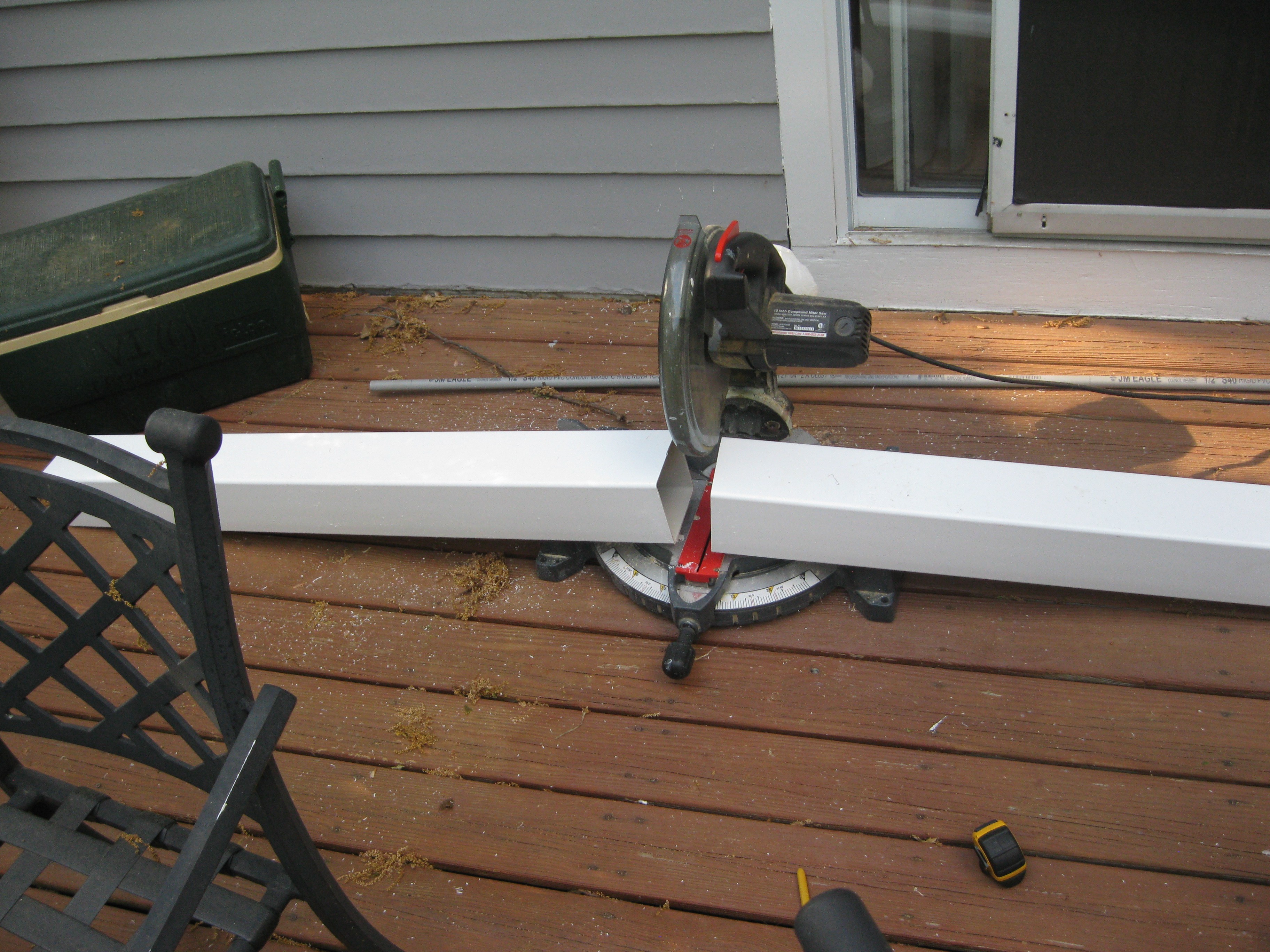
Cutting Fence posts, I bought two 8 foot lengths and cut them in half for four 4 foot units. Each unit will hold 4 plants in 3" diameter hydroponic plastic grow baskets, filled with hydroton grow media.![]()
![]()
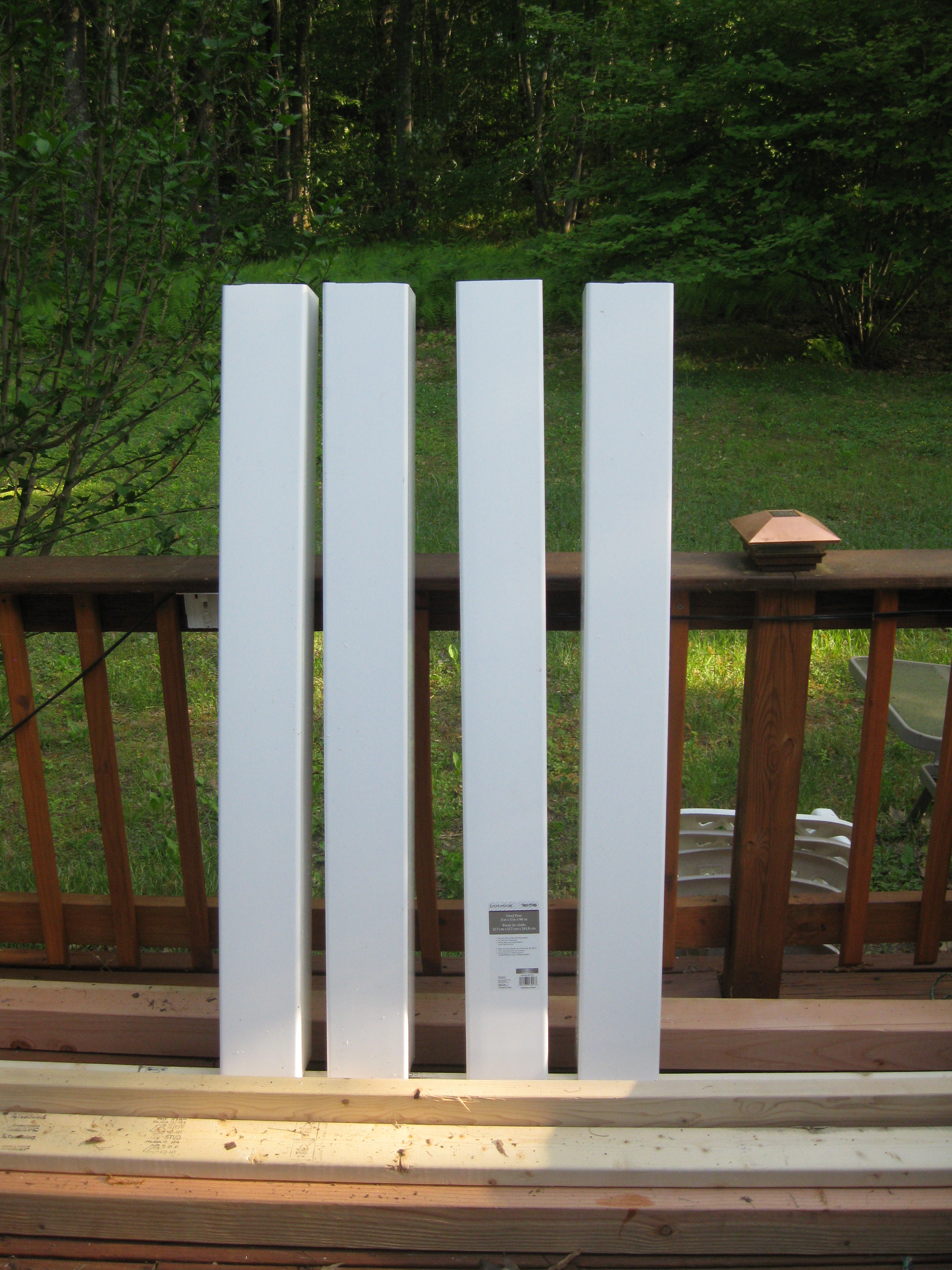
All Cut, the chop saw wasn't big enough to fit the whole width of the post so I had to rotate it 3 times to cut them, I don't recommend this but if you do wear safety glasses and be very careful.
![]()
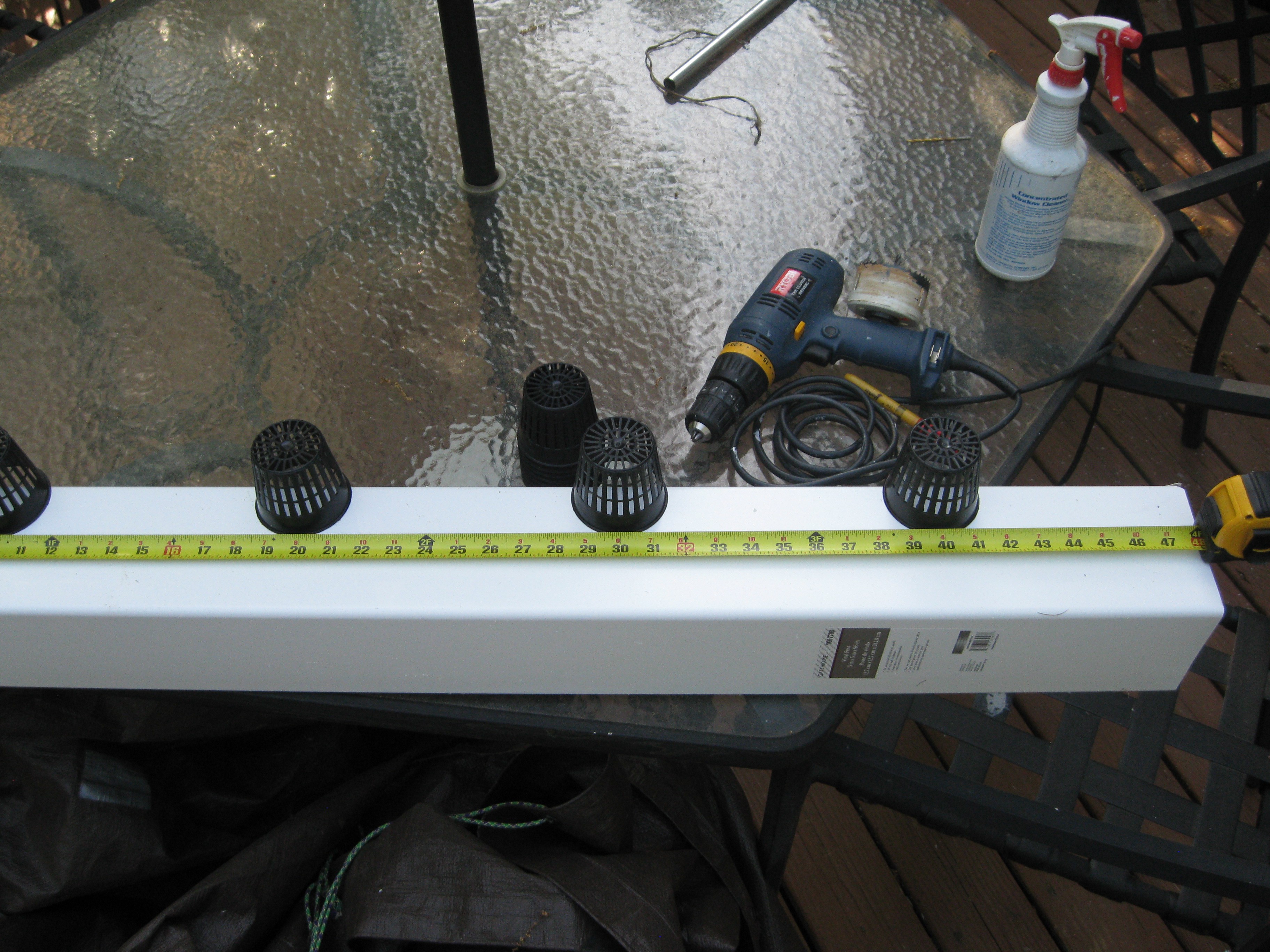
Measuring spacing of the plant pots and drilling pilot holes for the hole saw. I was planning on using my 3 inch hole saw to cut holes for the pots but the drill (on the table) I have won't fit the hole saw. I need to borrow a friends drill to finish. Next off for building the unit will be the frame, I haven't decided what the frame is going to look like. Simple requirements for it will be to mount the 4 rows and be tall enough to fit a 55 gallon water barrel underneath to act as the reservoir for the system. I plan on using the 4X4s to make legs and to build the rest of the frame with the 2X4s.
![]()
So thats what I got done on the unit so far, I'm hoping to do some more work Friday if its nice outside to use the saw, stay tuned for more updates later!
HydroPWNics
An open source hydroponic garden control, monitoring, and grow system with cloud database and dashboard.

 Stay tuned for more updates over the weekend!