STEAL-THIS-HARDWARE
-
Future, Next Phase, Refresh/Rebirth
06/27/2020 at 20:52 • 0 commentsHey folks just an update saying this project is not dead, its in the process of being refreshed as part of my latest agriculture sensing platform Agricoltura IO you can learn more about it here: https://hackaday.io/project/173362-agricoltura-io
Agricoltura IO Is a agriculture sensing and control platform relying on a RS485 sensing and control nodes that are controlled by a gateway control that links RS485 and wireless networks together pushing their data into a cloud database and browser control panel. Agricoltura will become the new electrical system for HydroPWNics and its family of projects including SunLeaf. The plan is to deploy and develop the system using the NFT grow unit developed for HydroPWNics, expect updates to this page down the line once I have working hardware in hand to deploy on the NFT unit in my basement. Please follow the main Agricolutra IO project for the latest updates around the new control and sensing hardware.
https://hackaday.io/project/173362-agricoltura-io
Stay tuned for more updates
-
HydroPWNics V2
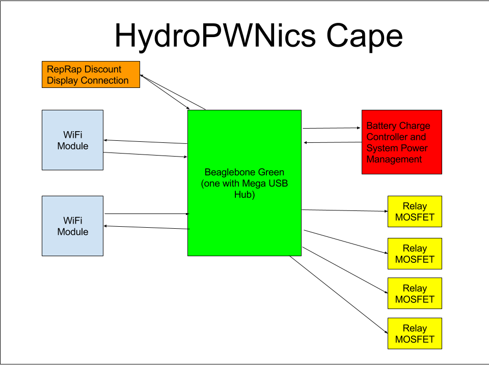
05/05/2016 at 23:40 • 0 commentsA lot has happened since the last update! Its now time to start over with the HydroPWNics electrical and control system, the initial one while having a lot of good ideas and qualities ultimately was too complex and plagued with many mistakes in the hardware design. At first I was going to just redesign the separate modules, eliminating the design errors but then I decided to roll all their functionality into a single module. This new concept of a singular module has has been spun off as a separate project called SunLeaf which aims to be general purpose for all sensing applications. The new HydroPWNics electrical system will consist of a custom designed Beaglebone Cape housed in a single box with relays and AC outlets, eleiminating the control box and AC control box from the whole system. For sensing and monitoring SunLeaf Modules willbe flashed with an alternative firmware to auto join with the Beaglebone cape dubbed the HydroPWNics Cape.
The Contents of the cape is pretty simple. On board there will be two WiFi modules, one module will be for connecting the Beaglebone to the internet via the home WiFi network the other module will be for creating an adhoc network for connecting to SunLeaf modules. Also on board there will be power management circuitry to run the whole system off a battery if power is lost , a set of MOSFETs for relay control, and a RepRap discount display connector (hello incorporating existing open source tech ).
![]()
-
HydroPWNics is Back!
02/24/2016 at 18:57 • 0 commentsHello!!!! Its been a very long time since I last updated the project page or posted a log. First and foremost I would like to thank the community for its tremendous support of the project and all your kind words, the positive encouragement of this community helped give me the drive to take this project as far as I did, so thank you!!!!
So without further do some updates. By the end of the Hackaday prize HydroPWNics only achieved partial completion and partial functionality. The main complete components were the NFT grow system built from PVC pipe and fence post and the LED grow light. The rest of everything was only partially completed. For the most part enough got completed to deploy the garden/grow system in "manual mode" in other words I took care of it and maintained it by hand like my other gardens/plants. I tried to run it this way for about two months before I decided that my lighting was inadequete and that the whole system could use an overhaul, the plants did stay alive for that time but they didn't grow much, but that's ok no one is an expert their first time around!!! The remainder of this winter and the coming spring will be deicated to overhauling HydroPWNics and bringing it to complete functionality.
The new direction of the project is to turn focus to hardware and software. Currently the hardware is being redesigned to correct design errors found with the original boards. First the plan was to just revise the analog/digital modules and the module hub but after doing the analog module and starting the digital module I decided that this might not be the best way to do things. So since last weekend I have been working to roll the digital and analog modules along with the module hub into a single standalone board. The idea is that there will be many of these boards in one system all doing different things. This new module is called the AD Module AD being short for Analog/Digital. Additionally I am also designing a smaller version of this module with onboard sensors, this module will be very similar but will be focused on monitoring the climate of a garden, light, temp, and humidity plus some addon ports. There will be a dedicated post discussing the specific of the new hardware down the road, everything is still subject to change.
As far as software goes, so little got done during the HydroPWNics project that its all subject to change. Originally HydroPWNics was going to have a completely custom software system with a dedicated website and cloud database, it changed slightly when I chose to use and work with Vivaplanet.io but still it was mostly a custom system. The new direction for the software is focus on tight integration with Vivaplanet.io, in short I'm not attached to my original proposal so anything is possible now!
While HydroPWNics hasn't been updated at all since the end of the hackaday prize ended, there still has been quite a bit of effort towards other projects that are either related or an essential component to the system. While I was taking a break to meditate on the new hardware direction (see above) my collaboration Shane Kirkbride and his Vivaplanet.io colleague have been working on the following projects:
https://hackaday.io/project/8657-open-source-hardware-plant-health-monitor
https://hackaday.io/project/9694-ras-pherry-wireless-ph-sensor
https://hackaday.io/project/6032-hummingbirdThis is just a short update to give people the jist of what is going on, thank you again for the amazing support of the project and stay tuned for more updates!!!!
-
Finals
09/21/2015 at 20:50 • 0 commentsSubmited for finals
-
PlaceHolder
09/21/2015 at 20:24 • 0 commentsPlaceHolder
-
Plants are Getting Too Big: Transplant Time!
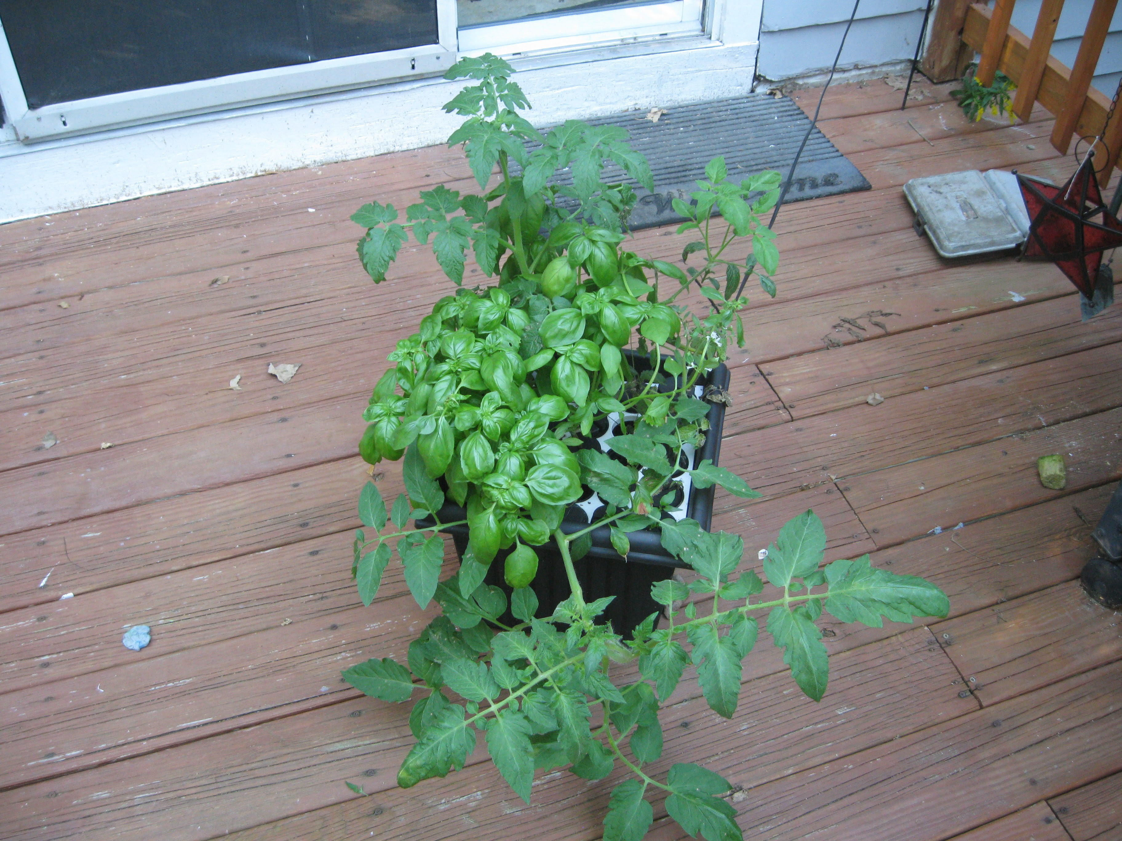
09/20/2015 at 00:57 • 0 commentsSo with this update I'm putting the plants into the NFT grow system from their cloner pot. They have grown so much and have pretty much out grown the cloner system. However not all the plants were ready, the jalapeno's need a bit more time for more vigorous root growth, and I decided to cut and reroot the giant tomato plant since it was growing in a rather weird shape.
![]()
Another Angle, you can see the giant unruly tomato plant I was referring too.
![]()
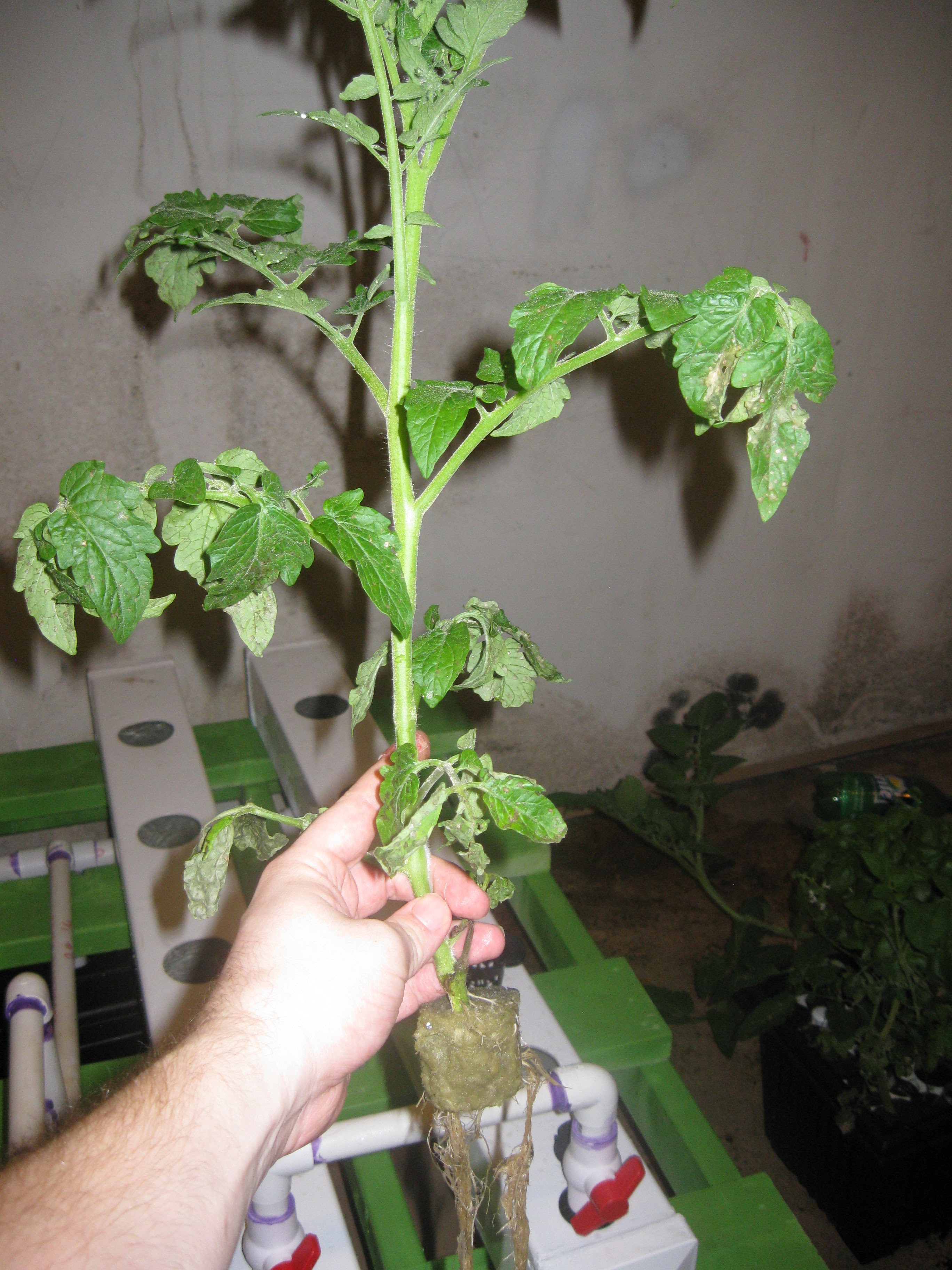
Here is the other tomato plant that was ready for transplanting. This one after rooting grow straight up like a small tree like it supposed to. It came out pretty good. Anyways the process for transferring the plants consists of carefully removing them from the small pot they were in the cloner preserving as much of the root growth as possible. You will lose some roots in this process but they will grow back once in the NFT system.
![]()
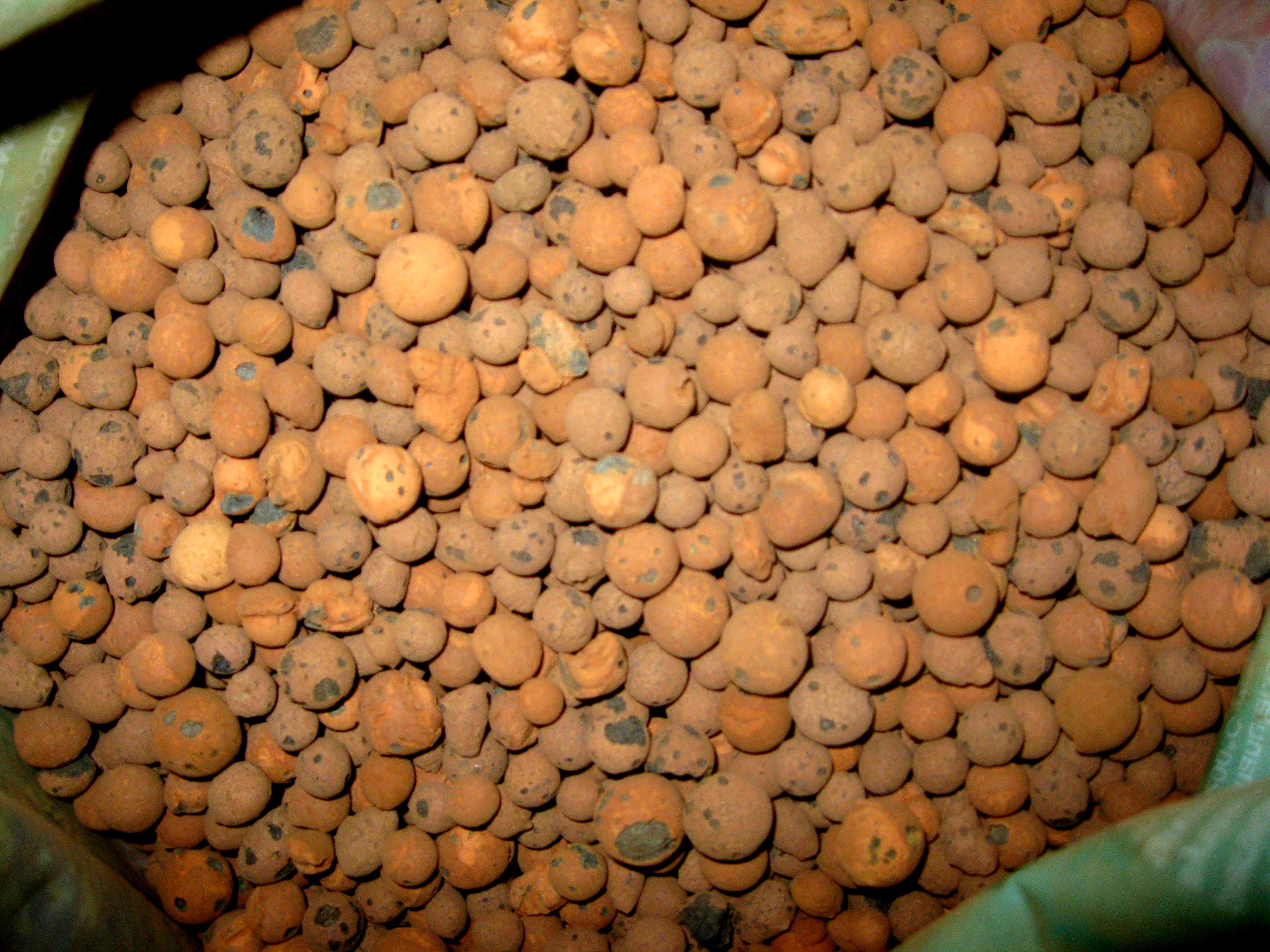
After the plants are removed from their smaller cloner pot its time to put them in the larger 3" pots meant for the NFT system and to add terracotta grow media. Folks usually choose between pearlite and terracotta granualary grow media. I made the decsiosn long ago to use the terracotta pellets when I first got into hydroponics. They tend to cost more than peralite but so many people have told me that it really is the way to go, you can also recycle it by cleaning it like you'd clean any other part of the system. So its sort of not a disposable resource. Terracotta pellets tend to be expensive because they are almost always imported but honestly its worth the price since the pellets can be washed and reused over and over.
The Terracotta pellets:![]()
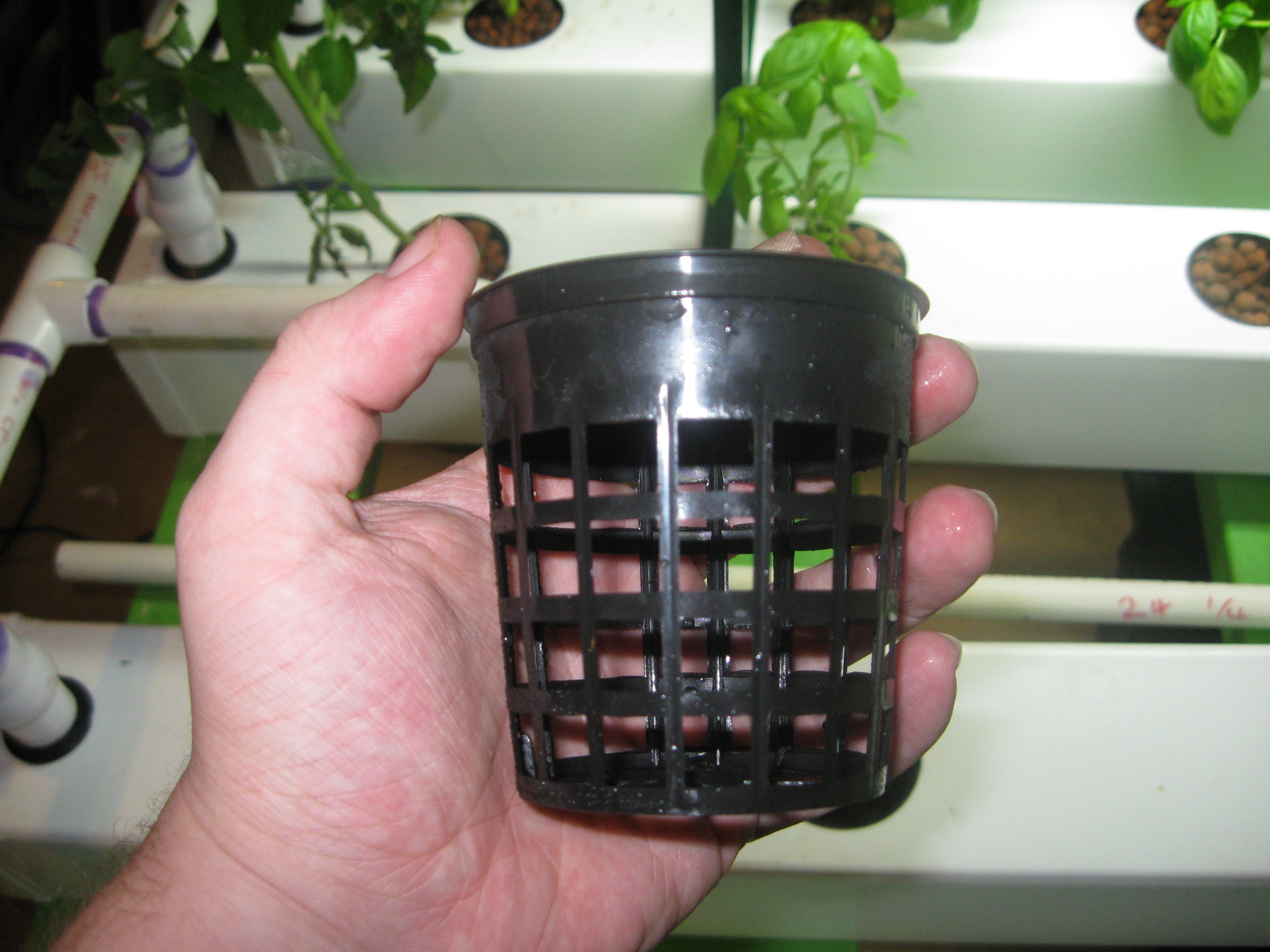
The larger 3" netted pot:
![]()
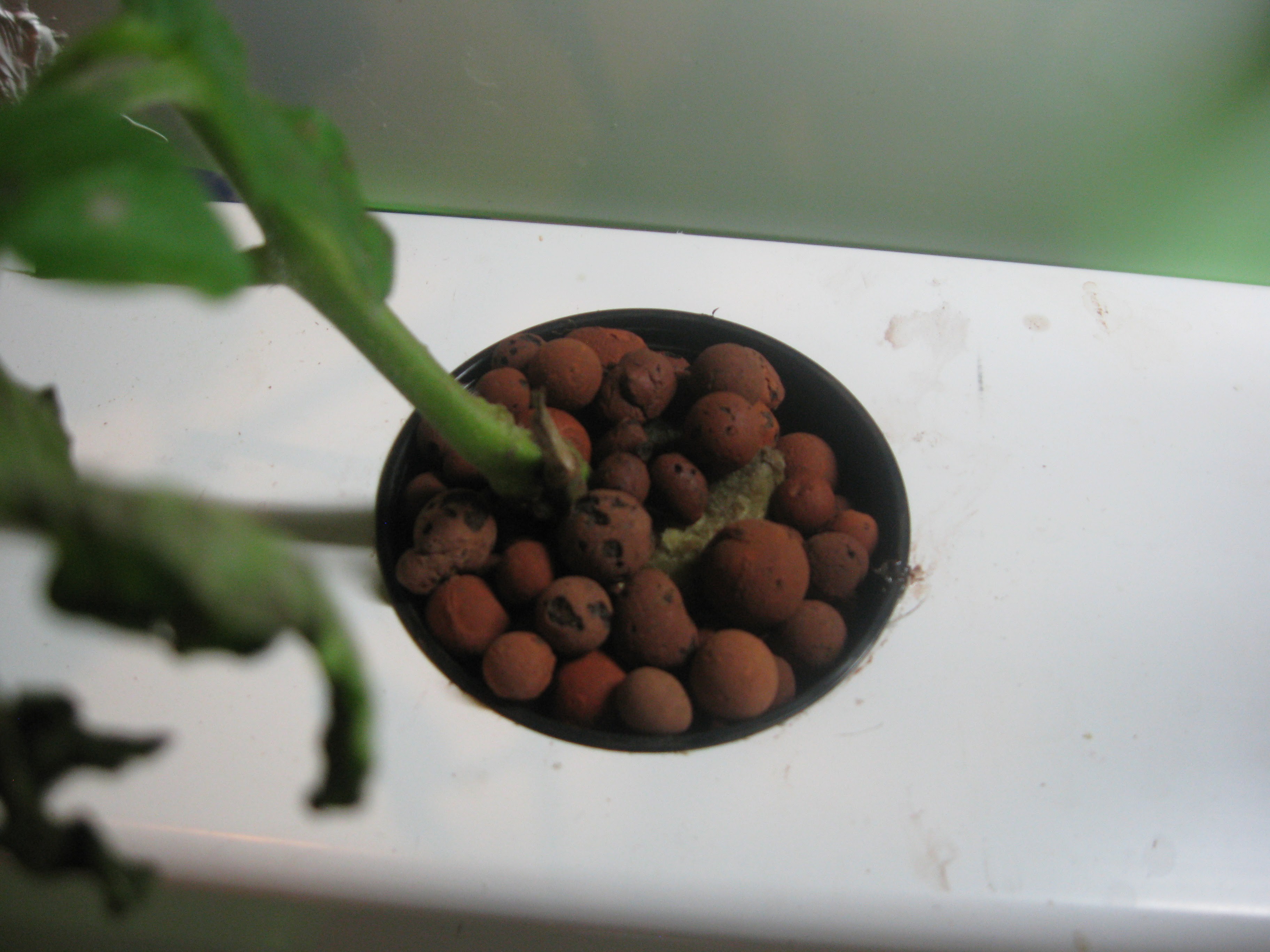
The process for placing the plant in the new pot is simple. First I carefully made sure the roots fell through the bottom while placing the plant rockwool cube and all into the pot. The space beneath and round the rockwool cube and the sides of the pot are filled in with the Terracotta grow media. The grow media helps hold the rockwool cube centered and covers it preventing algae growth. And ends up looking like this when finished:
![]()
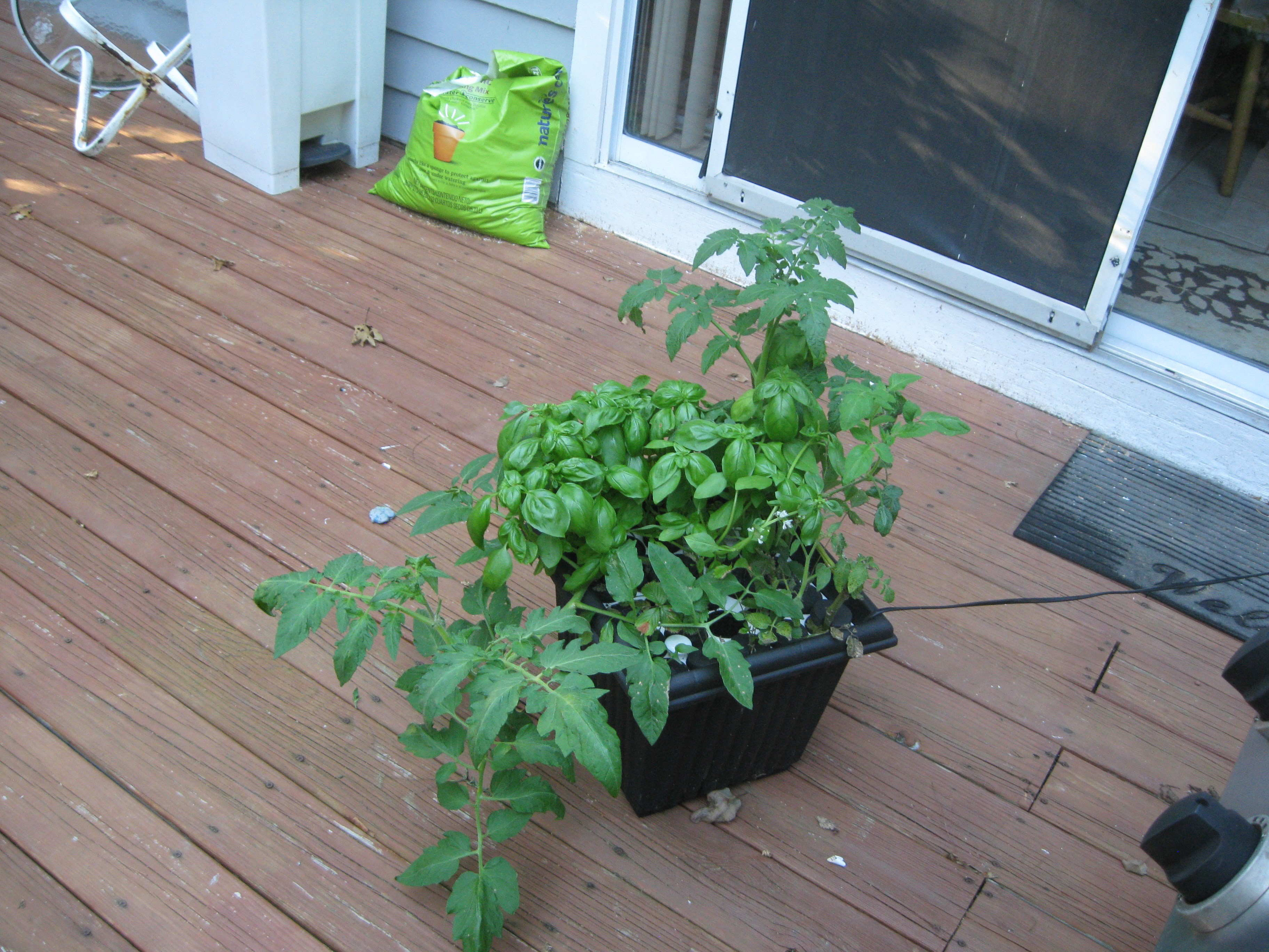
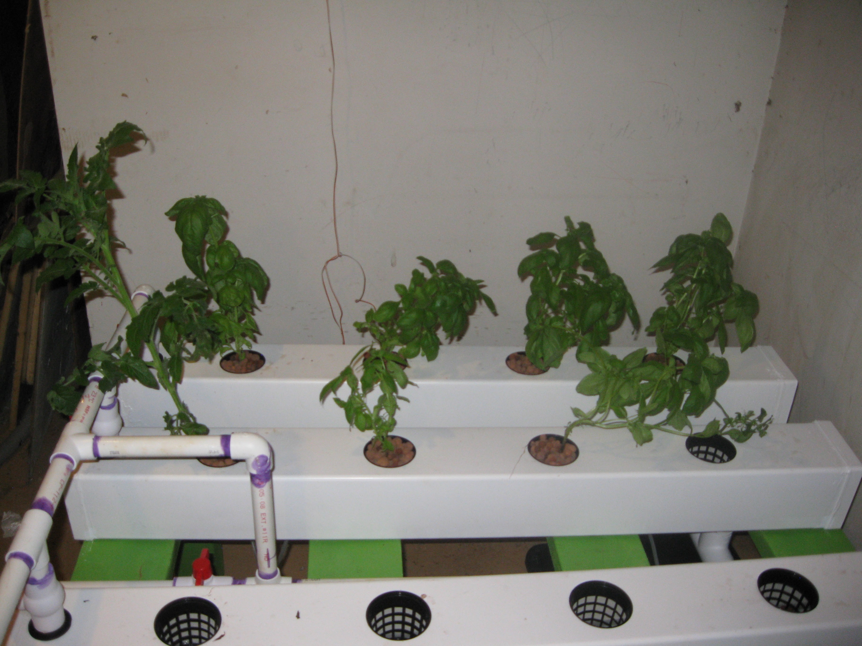
Tomato plant from before inplace as well as the first basil plant. I was in a rush so I didn't take as many pictures of this process but soon the other plants will be ready and I'll be sure to take more pictures !
![]()
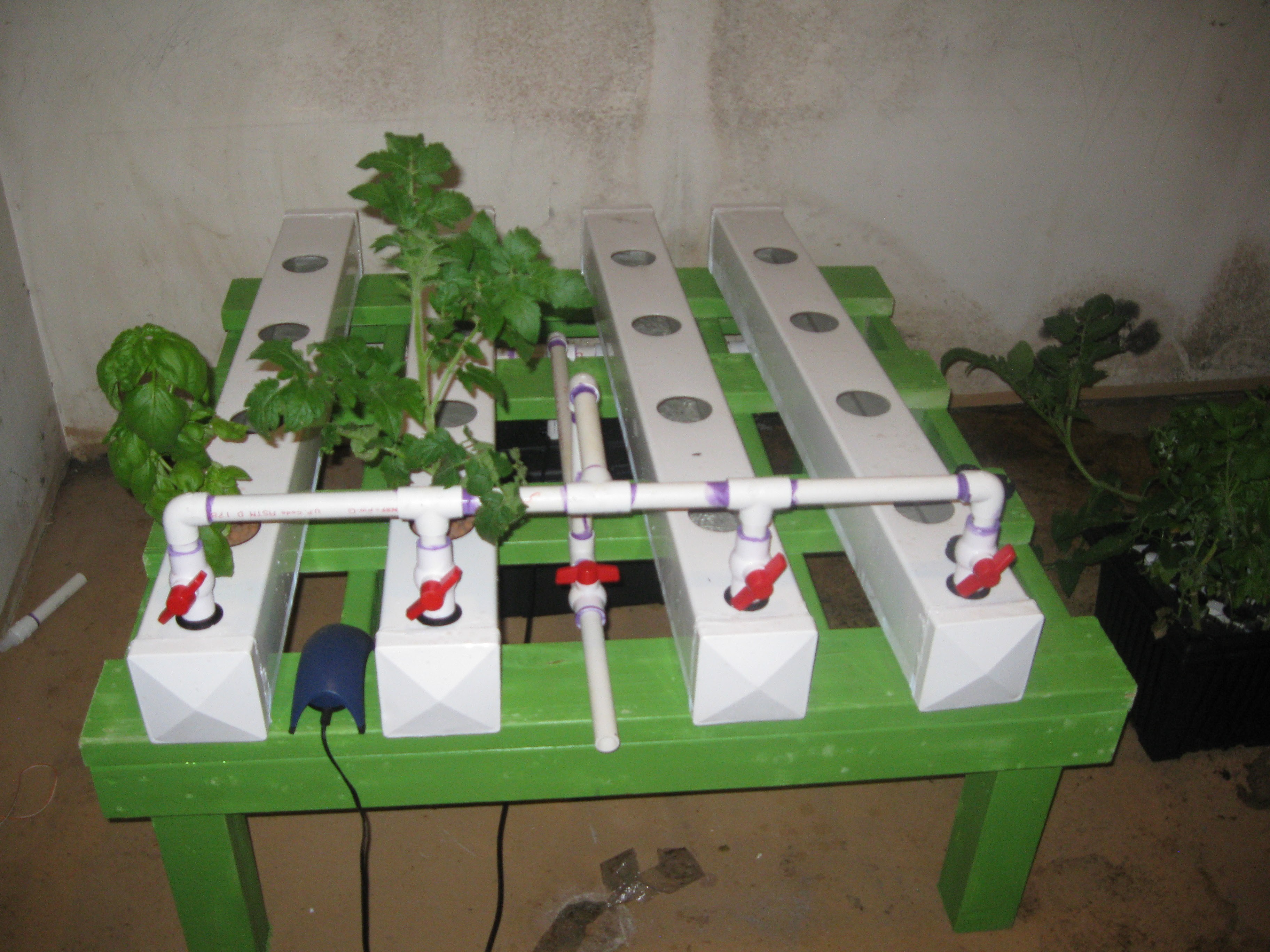
Side view of the plants that were ready and moved into place.
![]()
Front view
![]()
In the meantime while finishing the LED light, the plants will be under my small T5 grow light, its full spectrum but small. It will be fine in the time it will take to finish the grow light. Thats all for now stay tuned for more!!!!
-
New Pump and Circulation Test!
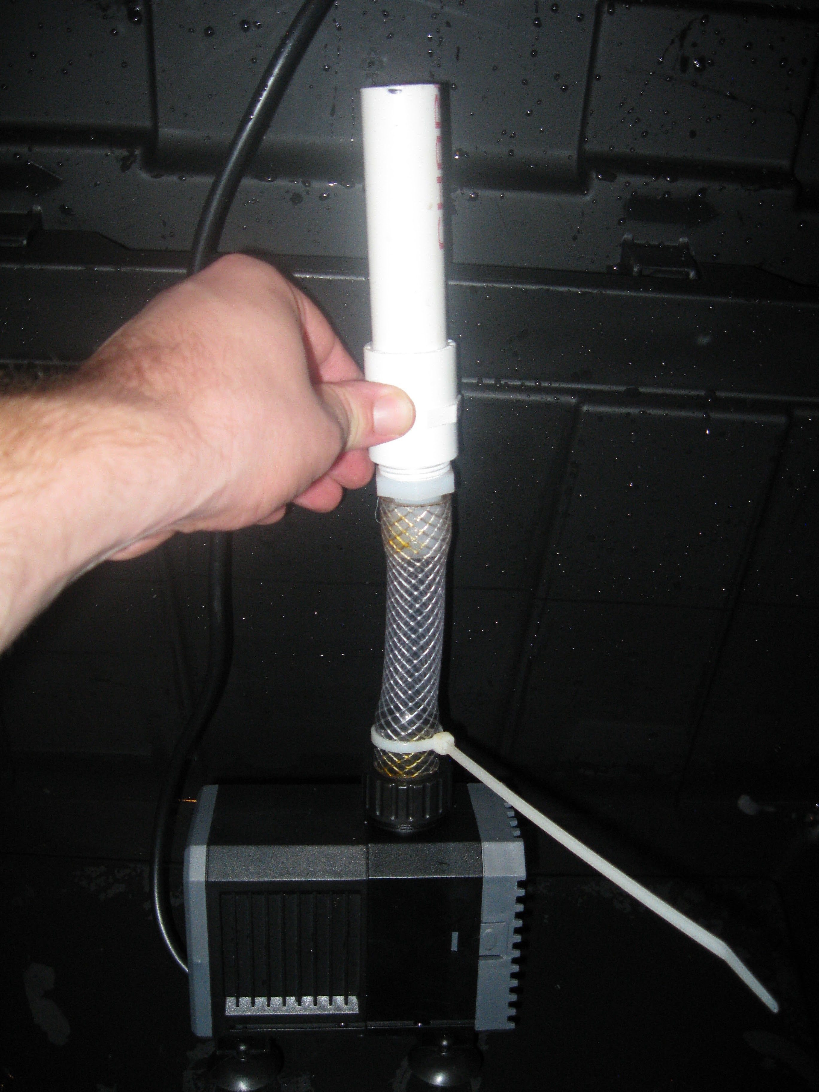
09/19/2015 at 23:12 • 0 commentsIn a recent previous log (I know I have too much of these) I hooked up the NFT grow system after moving it into the basement. After completing the setup and running a circulation test I discovered the pump was undersized for the manifold. If the manifold were constructed fro 1/2" pipe the original pump would have been fine, rather than making a new manifold I decided to buy a new pump after some research on the subject. The replacement pump is a SunSun CHJ-3000 800GPH Pump:
Pump in hand!
![]()
Over the course of this project I have been following all sorts of hydroponics groups on facebook and just passively absorbing knowledge and asking questions. This is when I realized the pump was too small, some nice guy shared this link with me http://nelsonwatergardens.com/choosing-the-perfect-pump/ it explains everything. After some on the fly head math and rereading of that article I settles on the CHJ-3000 and ordered it.
To get things started a dismantled the NFT grow system and took out all the parts I would be modifying/fixing.
![]()
The original pump had a 1/2 inch barbed fitting for its output, the new pump had a 3/4 inch barbed fitting. At first I used some 3/4 inch tubing I had on hand to adapt the fitting down to 1/2 inch to hook into the fitting on the manifold. I used a blowtorch to heat the tubing slightly to fit it together. While the results came out good I decided this was a bad idea, I didn't want to go from 3/4 inch to half inch to 3/4 inch again, I just sensed that would be a bad idea so I set off to hack a solution together cause after all this is Hackaday!
![]()
My hacked solution was so hacky in the end. I had a lot of fittings and parts left over from my past adventures in hydroponics as well as early inceptions of this project. I was able to find a threaded 3/4" barbed fitting and a fitting to adapt it to 3/4" PVC! Now the problem was how to connect this to the existing manifold, given that the pump input to the manifold had threads for a 1/2" thread for bolting on the flow meter in. This setup wouldn't work so I decided to cut it and attempt to salvage the fitting on end of the input manifold.
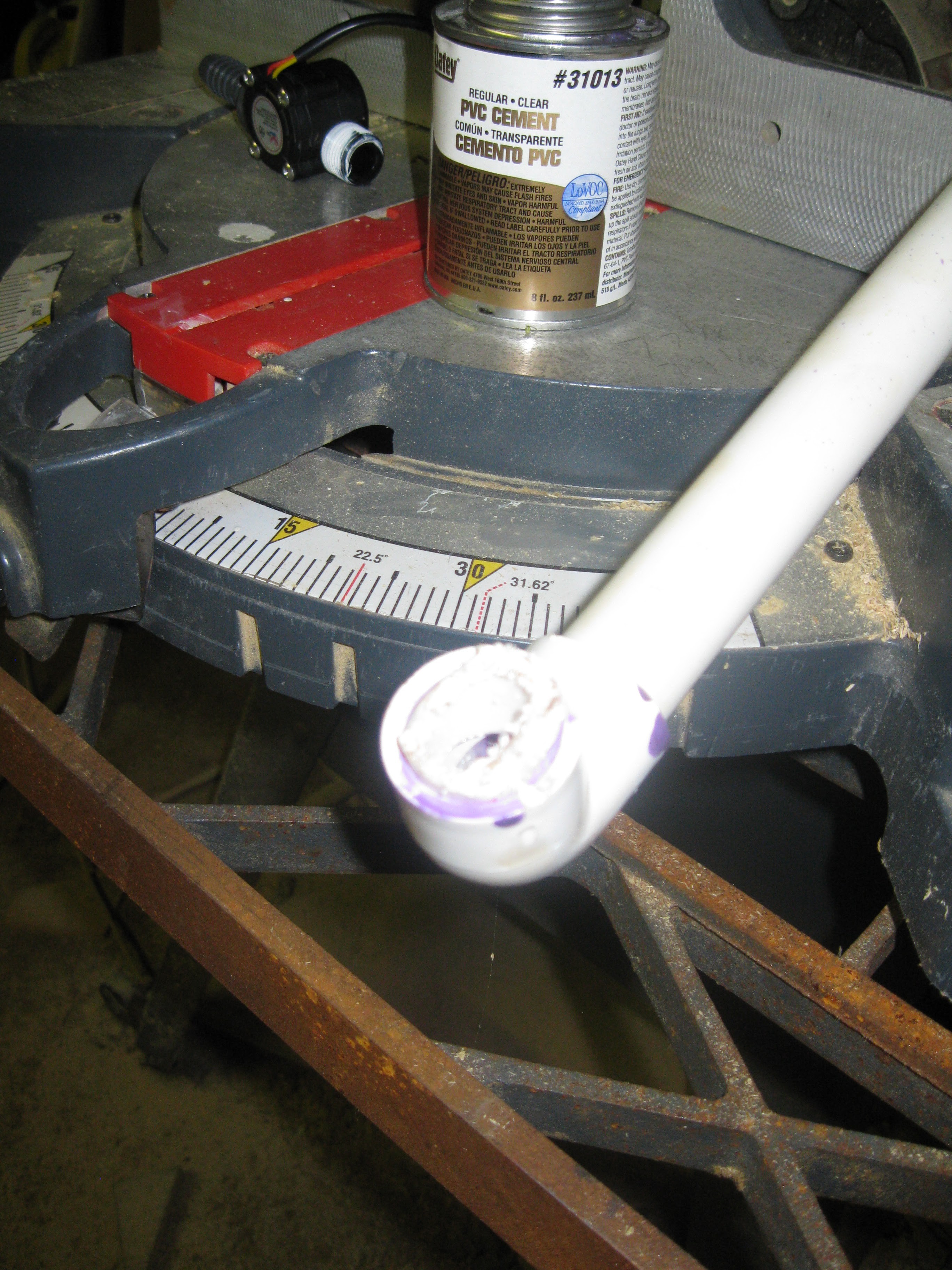
New 3/4" pipe/fitting adapter to connect the new pump to the manifold. The bit of pipe left in the right angle fitting on the input of the manifold had to be removed to fit this new pipe section into it, uniting the manifold and the pump.
So to start things off I cut off the fitting with the 1/2" threading. My attempt to remove the bit of pipe inside the right angle fitting consisted of clamping the excess pipe proturding from the fitting in a vice in hoping to forcefully tear the pipe from the sides of the inside of the fitting. The vice trick worked to an extent providing me with cracks between the bit of pipe inside and the fitting. The next step was to fill these cracks and the inside of the pipe piece stuck in the fitting with PVC cement. I don't know how popular this method is but I thought I'd give it a shot. After the PVC pipe piece inside the fitting soaks in the cement it can be torn from the fitting using pliers and a screwdriver to pry.![]()
![]()
Another view of the process:
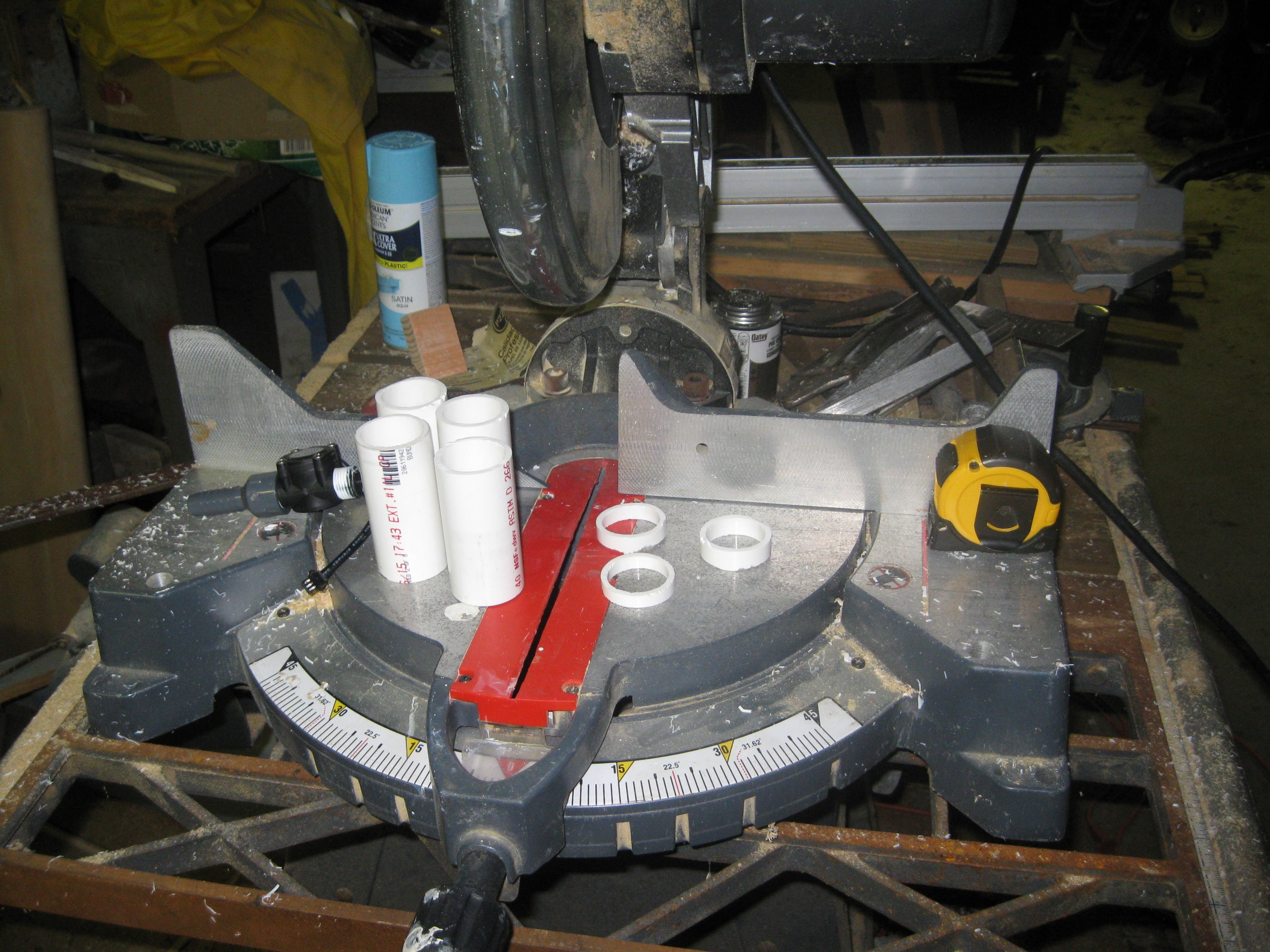
In the end after applying cement and trying to pull it apart over and over again I decided that this just wasn't going to work as well as I thought, so I came up with a new solution. I decided to cut off the right angle fitting entirely and to drill a new hole in the reservoir to move the pump closer as to line it up with the new position of the manifolds input. In the end I needed a longer piece of pipe for connecting the pump, the piece and fitting in the picture above were just a mockup.![]()
Longer piece with fitting ready to be glued to the manifold.
![]()
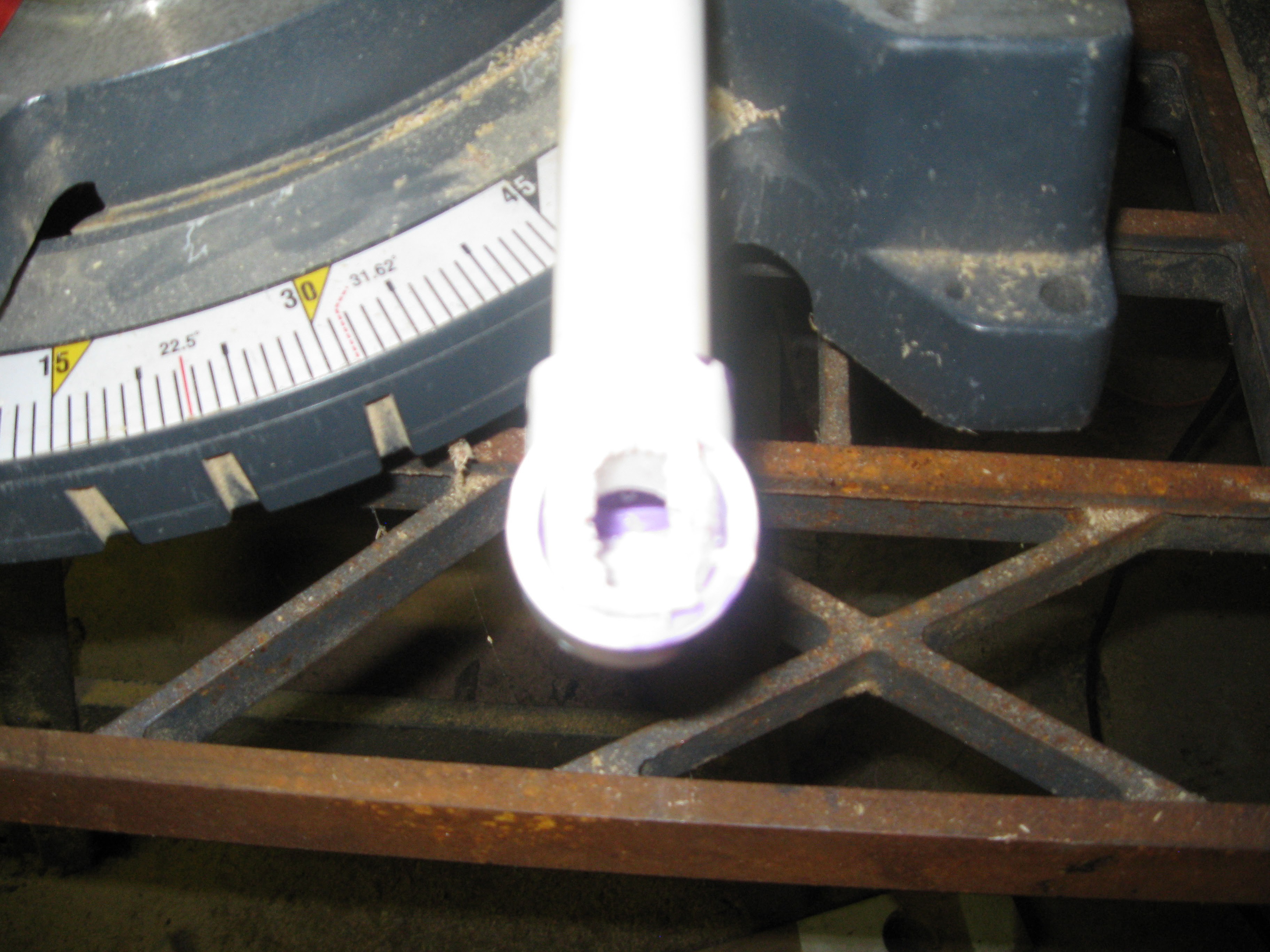
Next off I shortened the drain pipes for each row, I felt the water level was too high during the original test, and the goal of NFT is to cut down on water. I took the drains down from 4 inches down to 3.5 inches. I just cut the pipe with a mitre saw, since its fast and easy.
![]()
Next off now that the modifications to the input manifold had been made I glued in the new part and got ready to setup the whole system for another circulation test with the new pump.
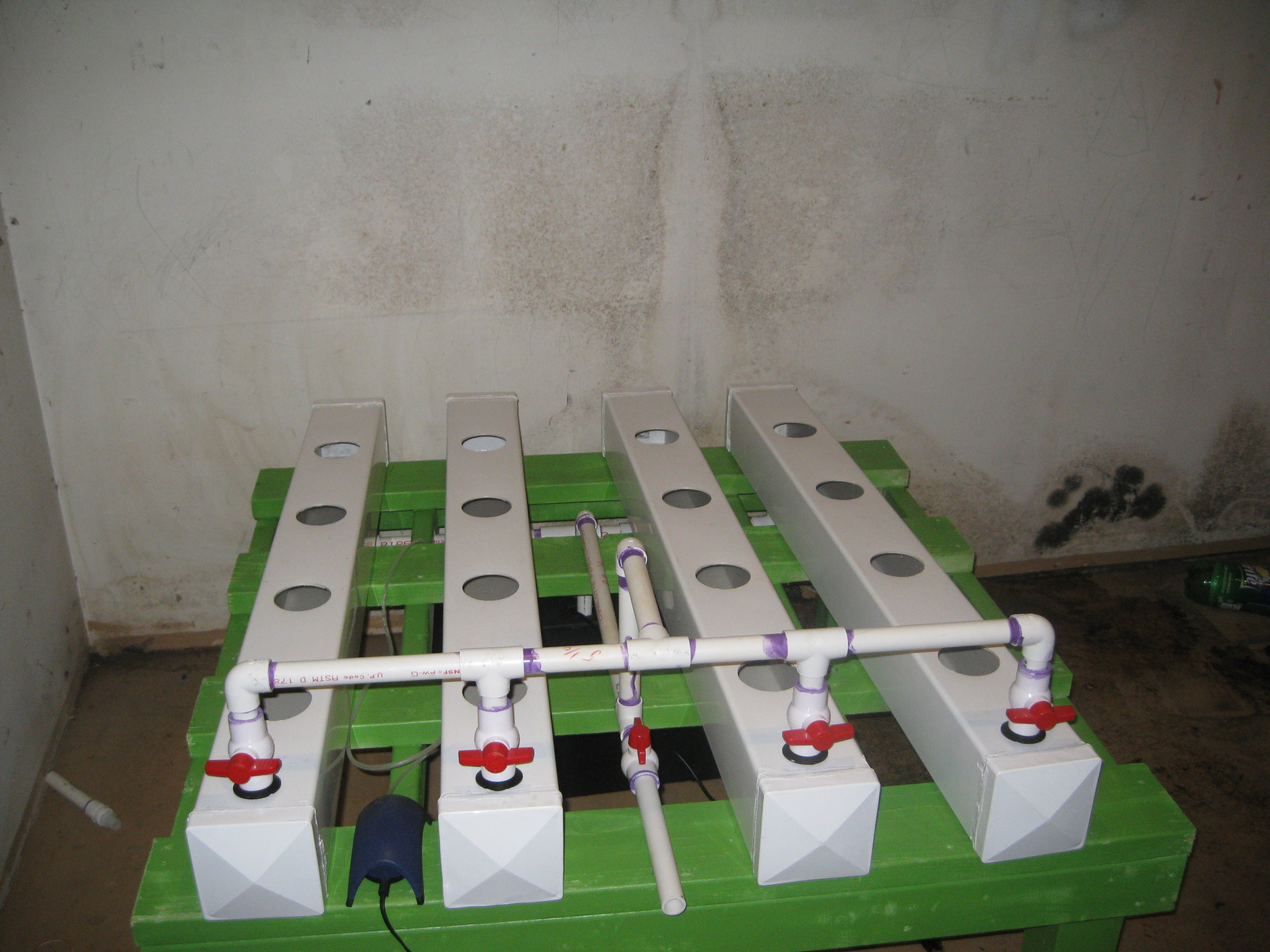
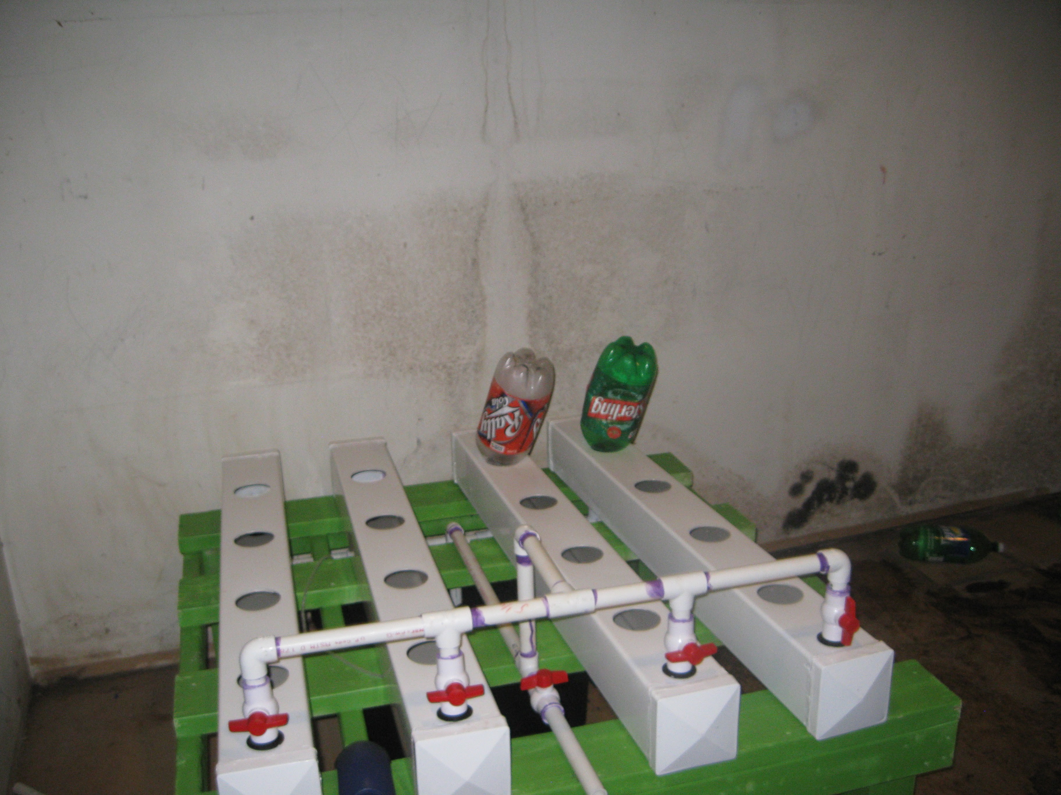
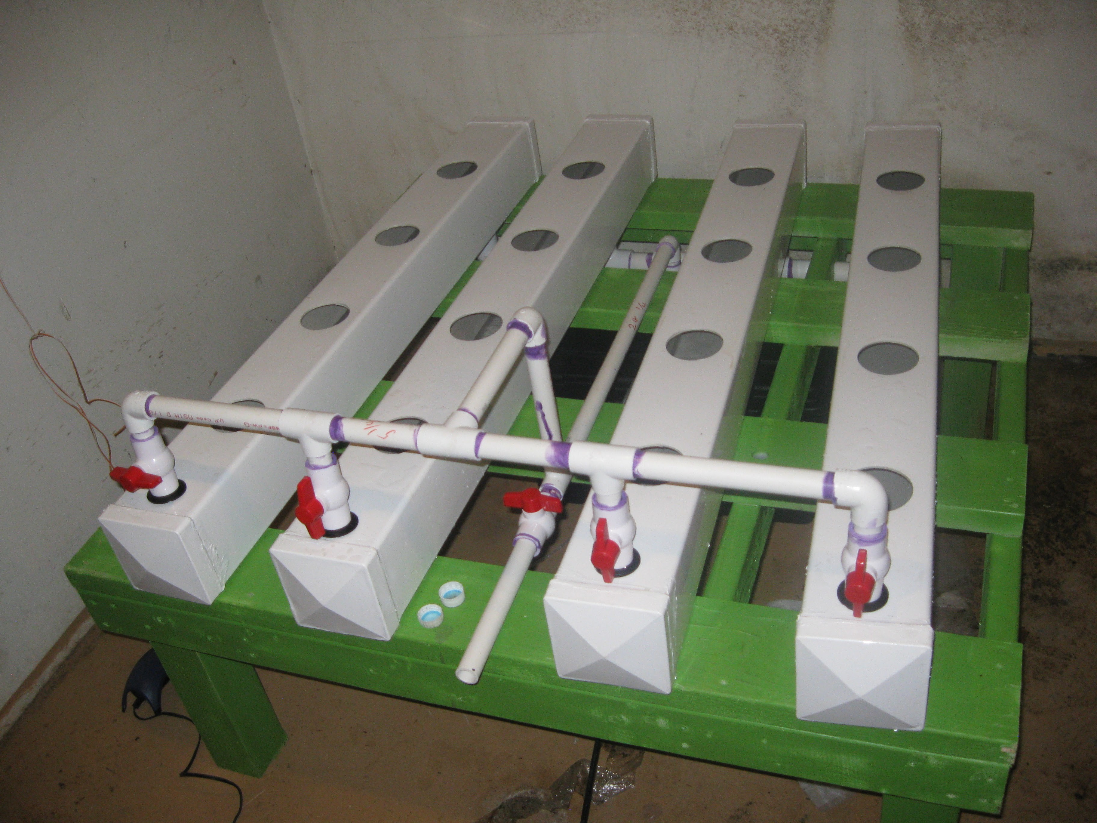
System all setup, input valves all closed, don't worry I closed the drain valve before firing up the pump!
![]()
Next I ran the tubing for the airstones into the original hole I had them going through. This time though the pump power cord comes out its own whole where the input manifold goes through to connect to the pipe. So what I thought was a flaw in the design turned out to be fine, I thought it was going to be hard to line up and hook the barbed fitting on the end of manifold into the pump through the hole but it ended up being really easy, the 3/4" tubing was just as hard/soft as needed!
![]()
For the circulation test I poured in water using 3 liter soda bottles into the final grow site at an angle to pour almost directly into the drain manifold. I had to put in about 6 of these bottles to get enough water in for the pump to be submerged. Once I got the water in I set it up to turn on the pump. Like before I closed all the valves but one row and opened them one after another successively after turning the pump on. I had to play with the valves and fine a middle ground between fully open and fully closed to get each row pumping in at the same rate. Eventually motors and sensors will do this autonomously.
![]()
After getting the water circulating in the system at the same rate through each row I added some MaxiGro nutrients and let them dissolve via the water circulating. The idea is to use the same nutrients for the first few days in this system so that the plants don't get stressed out from being transplanted. So anyways expect another update very soon, stay tuned!!!!
-
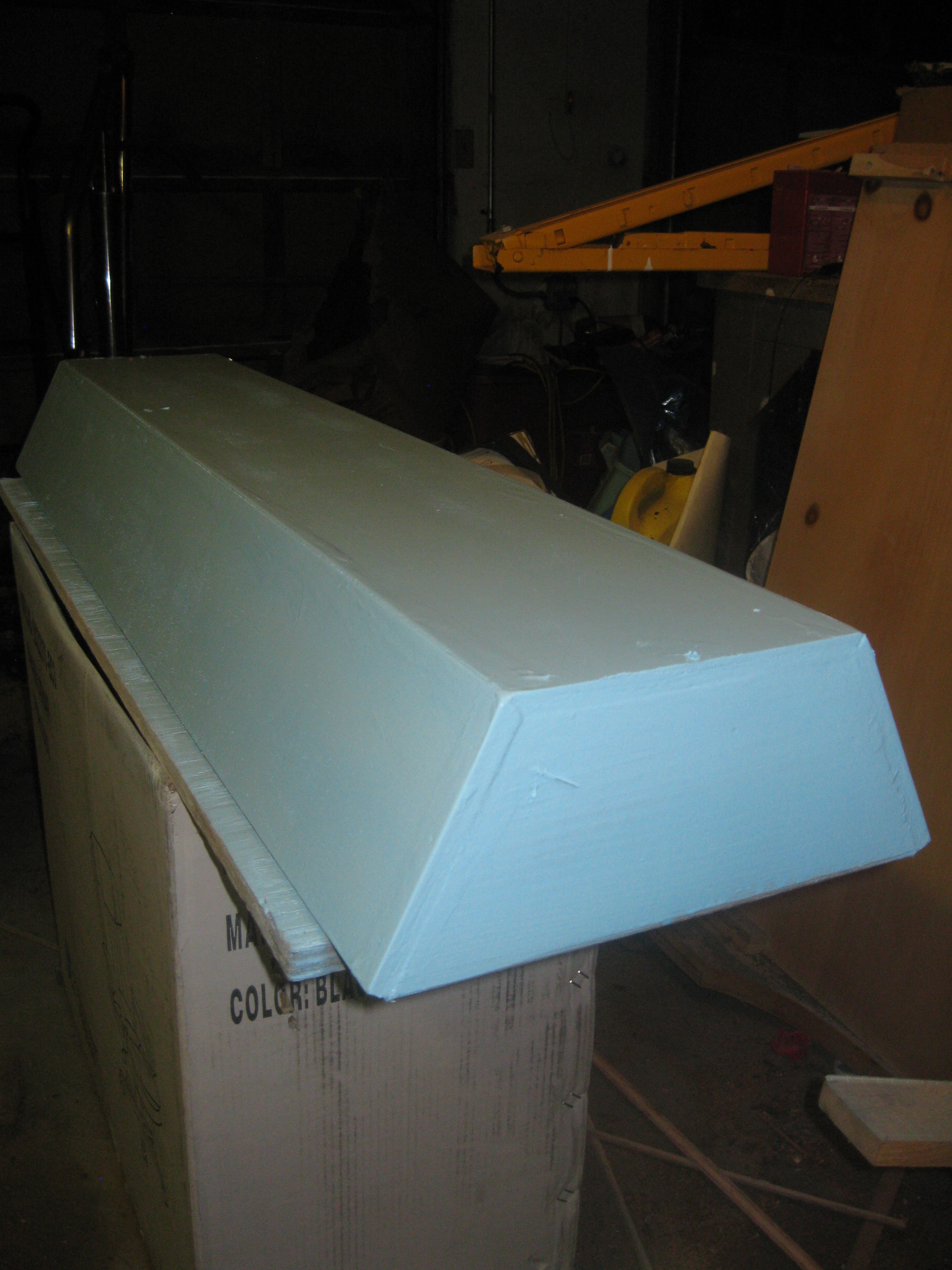
Grow Light Progress: More painting and Assembly
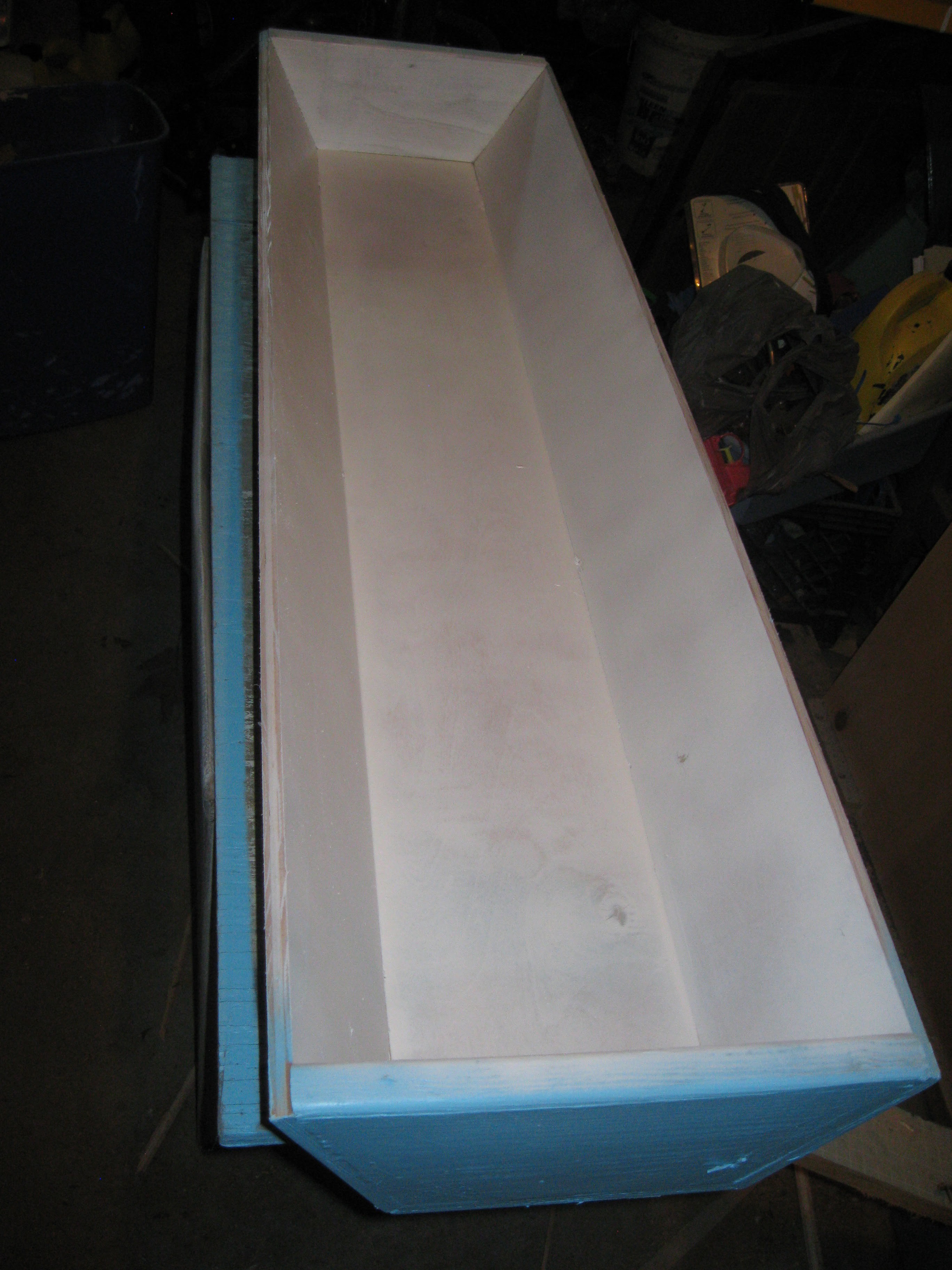
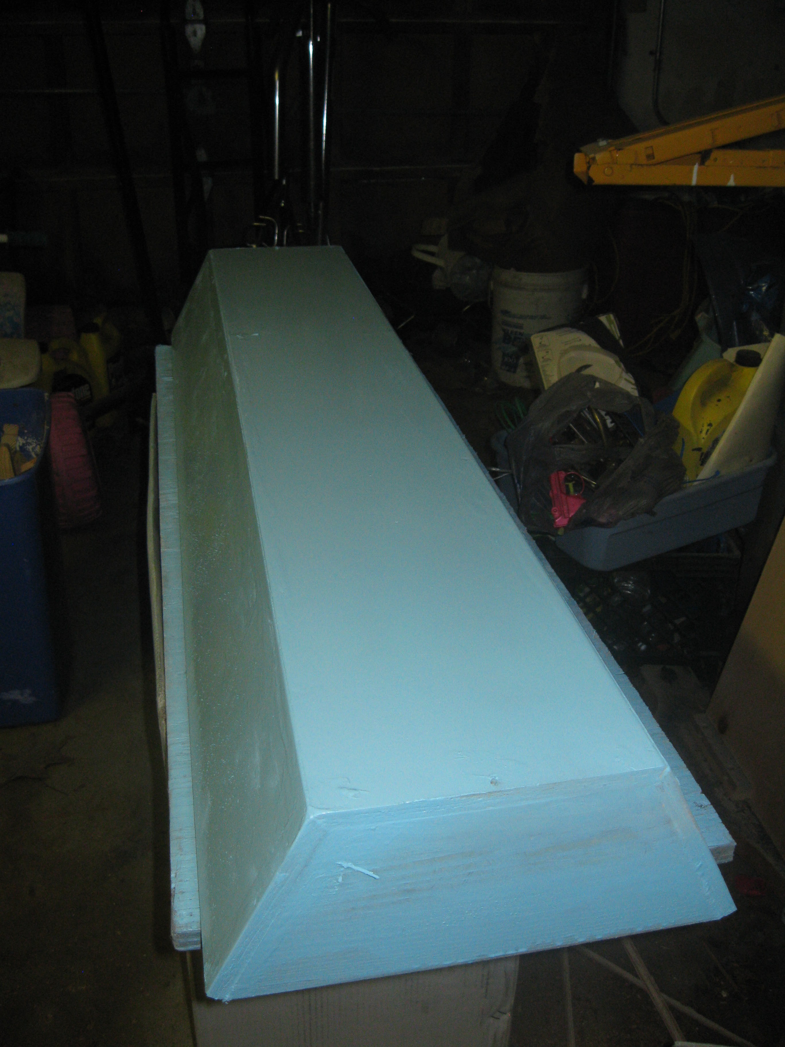
09/19/2015 at 20:27 • 0 commentsI promised more updates this weekend and well here it is! I spent a good amount of time finishing the grow lights. So on the grow light after the painting on the outside was finished I took to painting the inside of the light. Originally the plan was to use tin foil or a mylar space blanket for reflecting the LED light down towards the plants, I decided that eventually there will be so much LED strip applied to the inside of the light that all reflective material will be covered. I decided to paint the inside white and scuff the surface of the paint after drying to allow for better adhesion of the LED strips to the surface of the inside of the light.
Starting the first coat
![]()
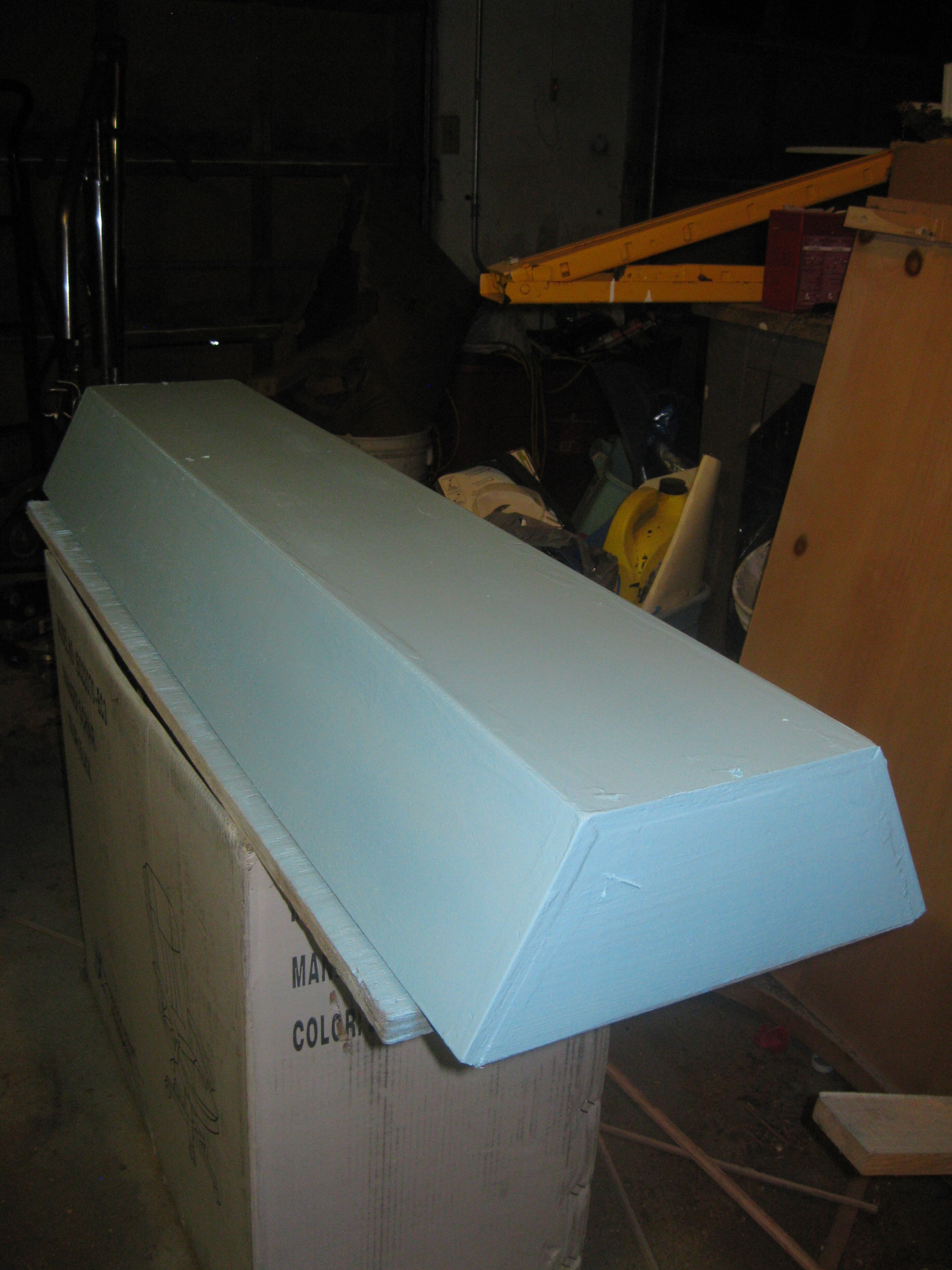
Almost done with first coat
![]()
More progress:
![]()
First coat finished:
![]()
Starting the second coat of paint:
![]()
Finishing second coat:
![]()
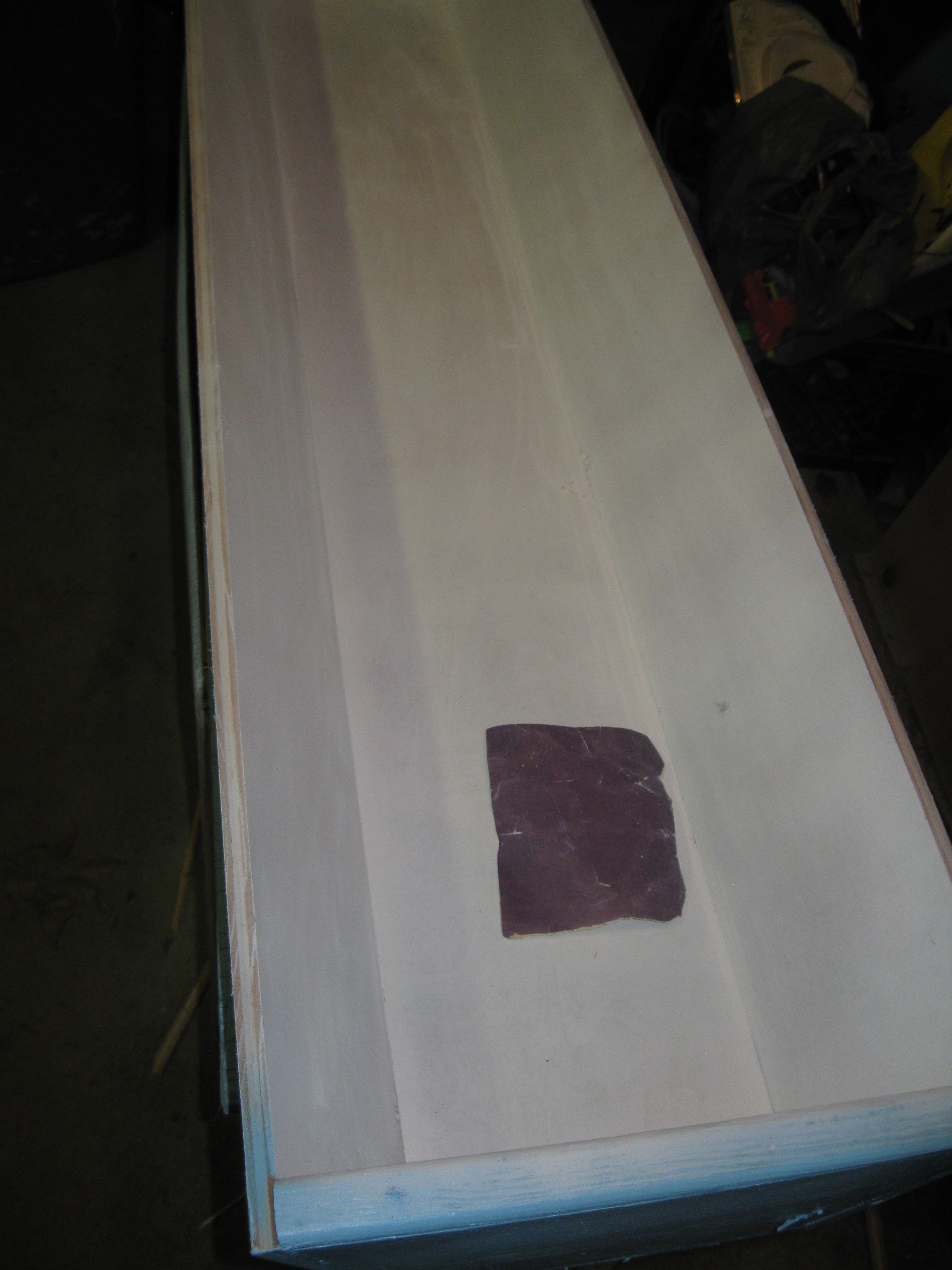
After letting the paint dry and cure all day I took to scuffing it up with sandpaper for better adhesion of the adhesive on the LED strips. I used 330 grit sandpaper, its my usual go to, its a nice compromise between fine and coarse. Of course if I were trying to get glass like finishes I'd be using all sort of paper but for this project, keeping it simple.
![]()
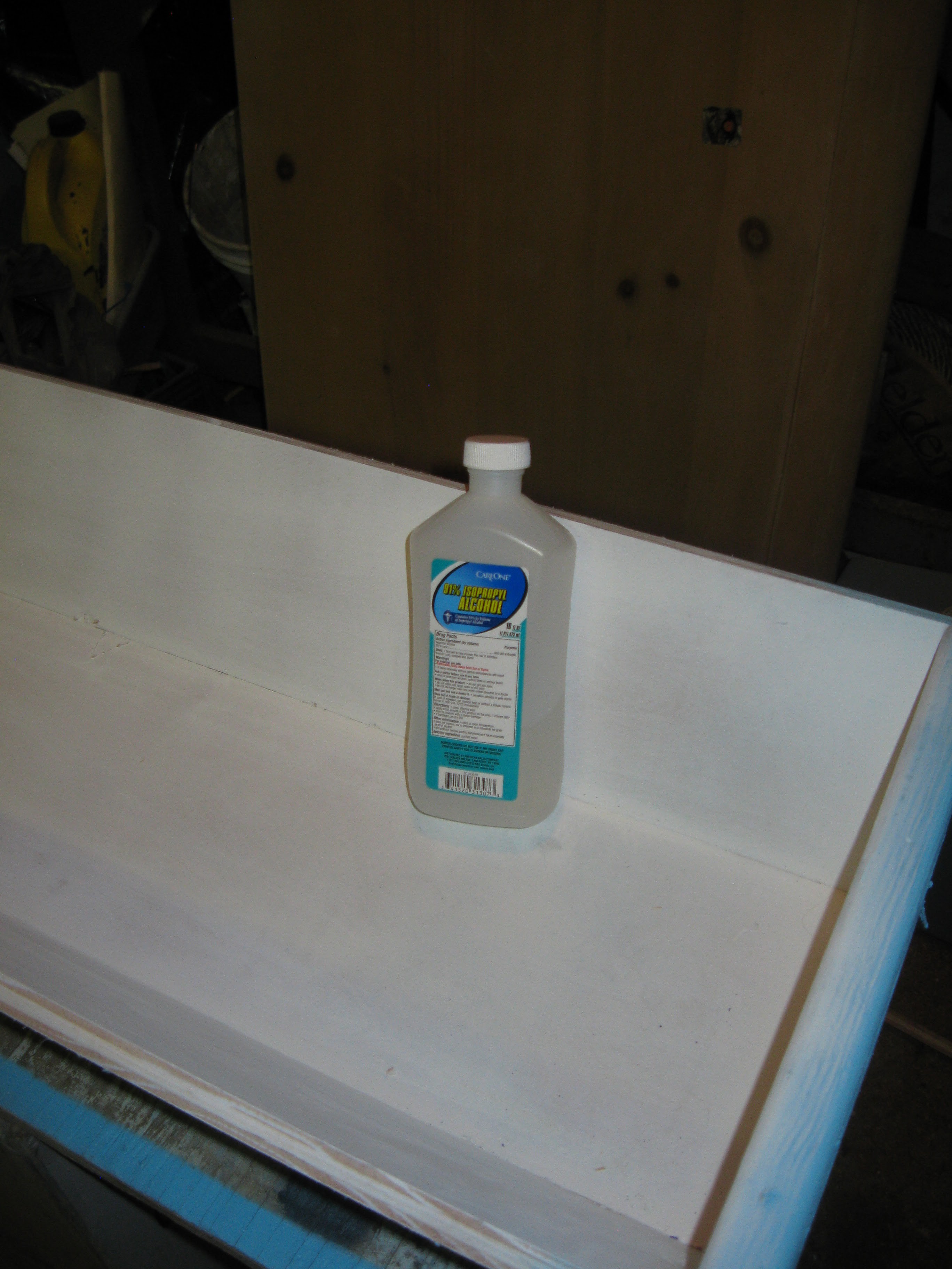
Cleaning off the sanded paint with a rag and rubbing alcohol
![]()
![]()
Next off I began to mockup the light casing with the strips in preparation for assembly. The mockup consisted of carefully placing the LED strips spaced apart in the light casing. Originally the strips were cut to approximate 4 foot lengths, but since the ends of the light casing are inside the case I lost some room and had to shorten the strips a bit.
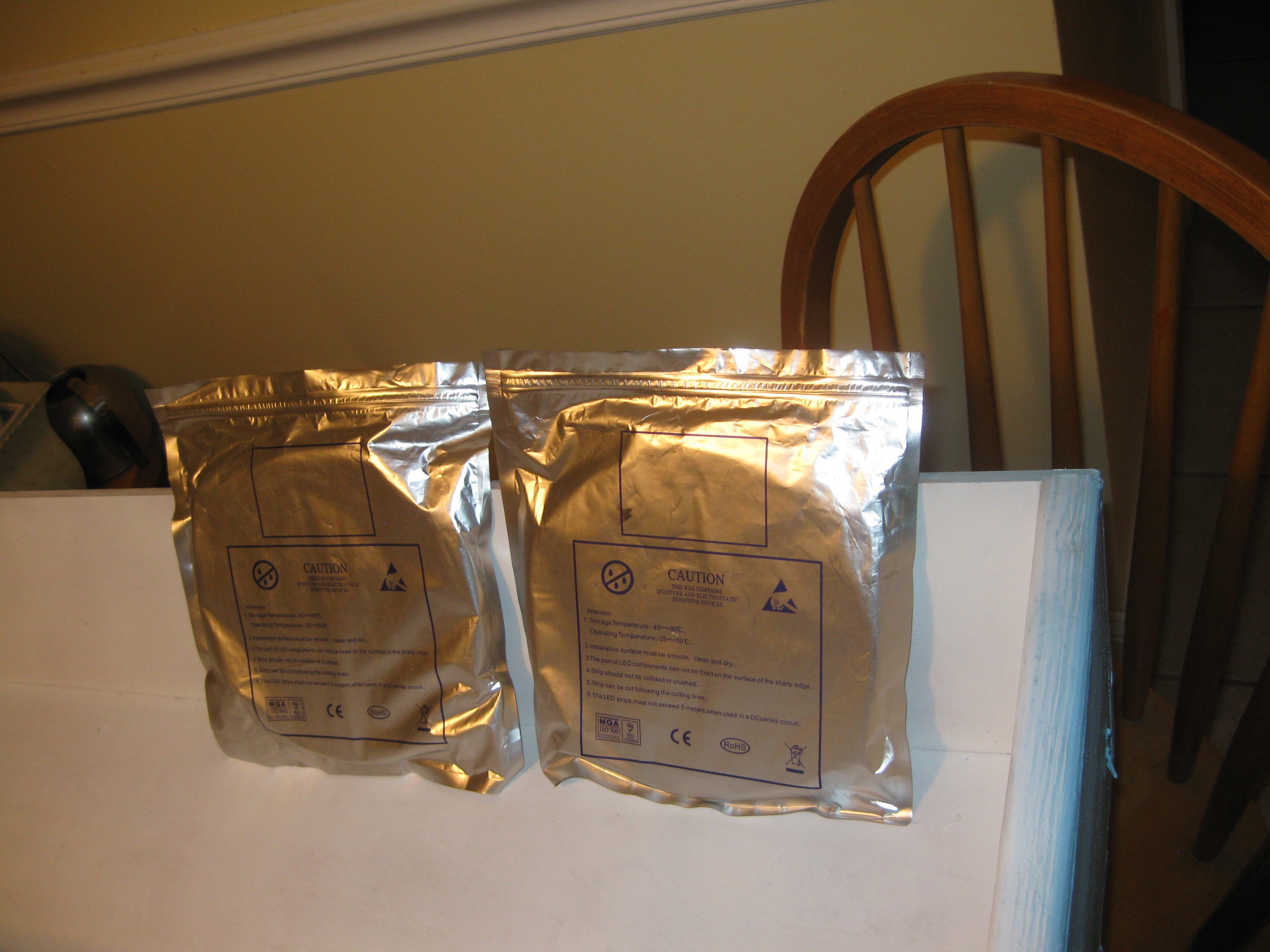
LED strips on their reels in the packaging they came in. Even though I cut them a while ago I still rolled them back on the reel for storage.
![]()
![]()
![]()
![]()
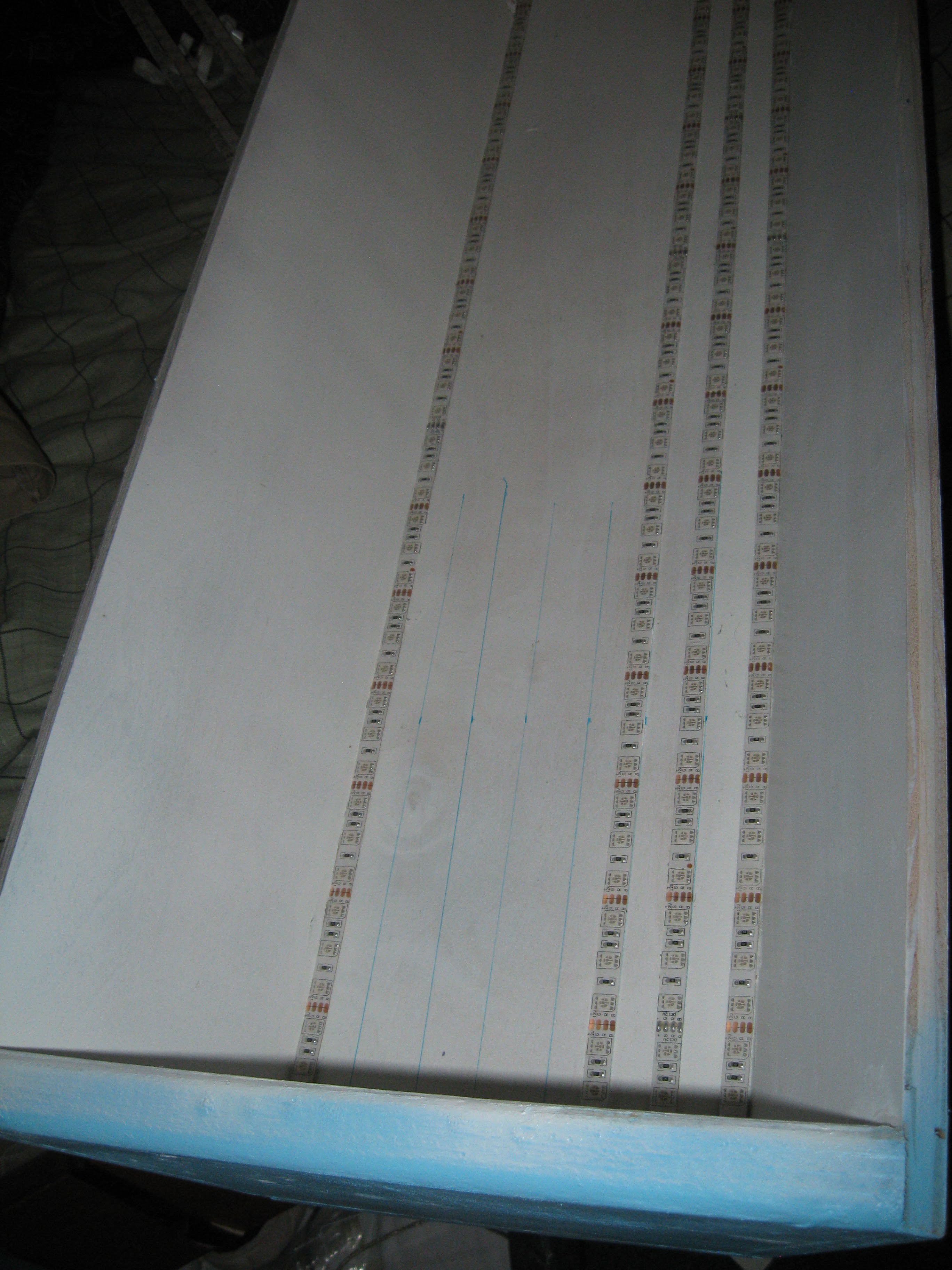
As you can see in the pictures there was a bit of excess strip on each length, I cut them at the marker, making the strips fit with enough room for wiring. I have been collecting the small bits of strip and saving them because when I get more strip there will be more leftovers, the idea is that I can join them all together and maybe get a few more lengths from just the scrap. Next off I used a ruler and sharpie to mark the spacing of the strips on the light. I did it at each end and lined it all up by hand.
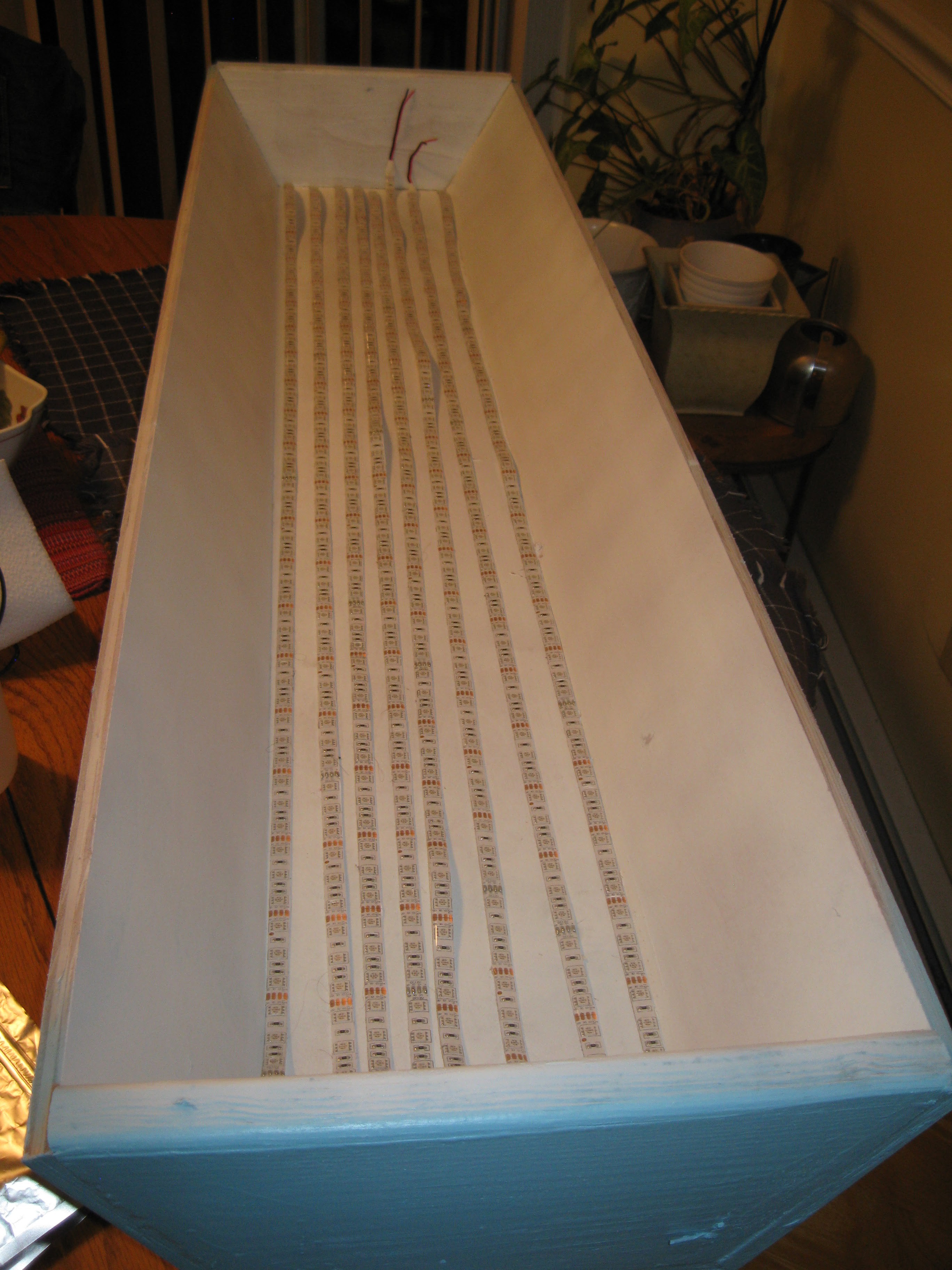
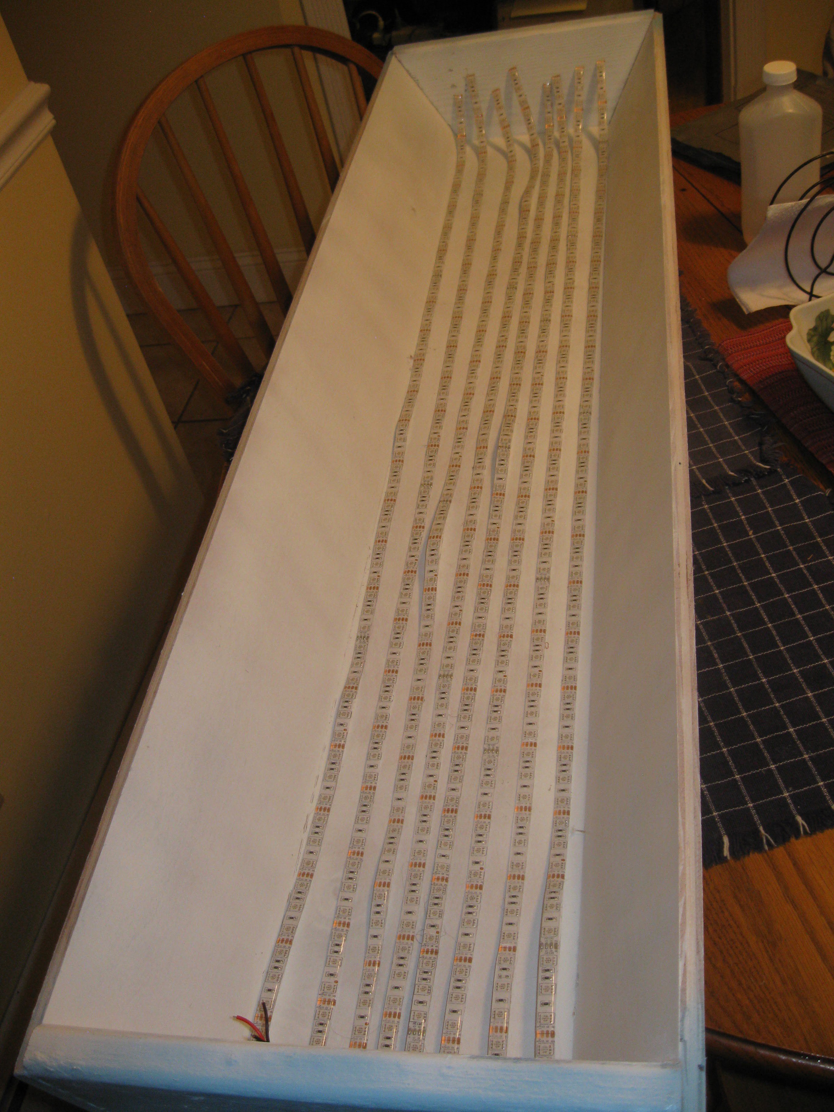
Lines drawn and some strip applied, the lines that the edge of the strip lines up with are spaced and inch apart, this gives enough space to put down more strips later to upgrade the light.
![]()
Close up of the strip application and markings:
![]()
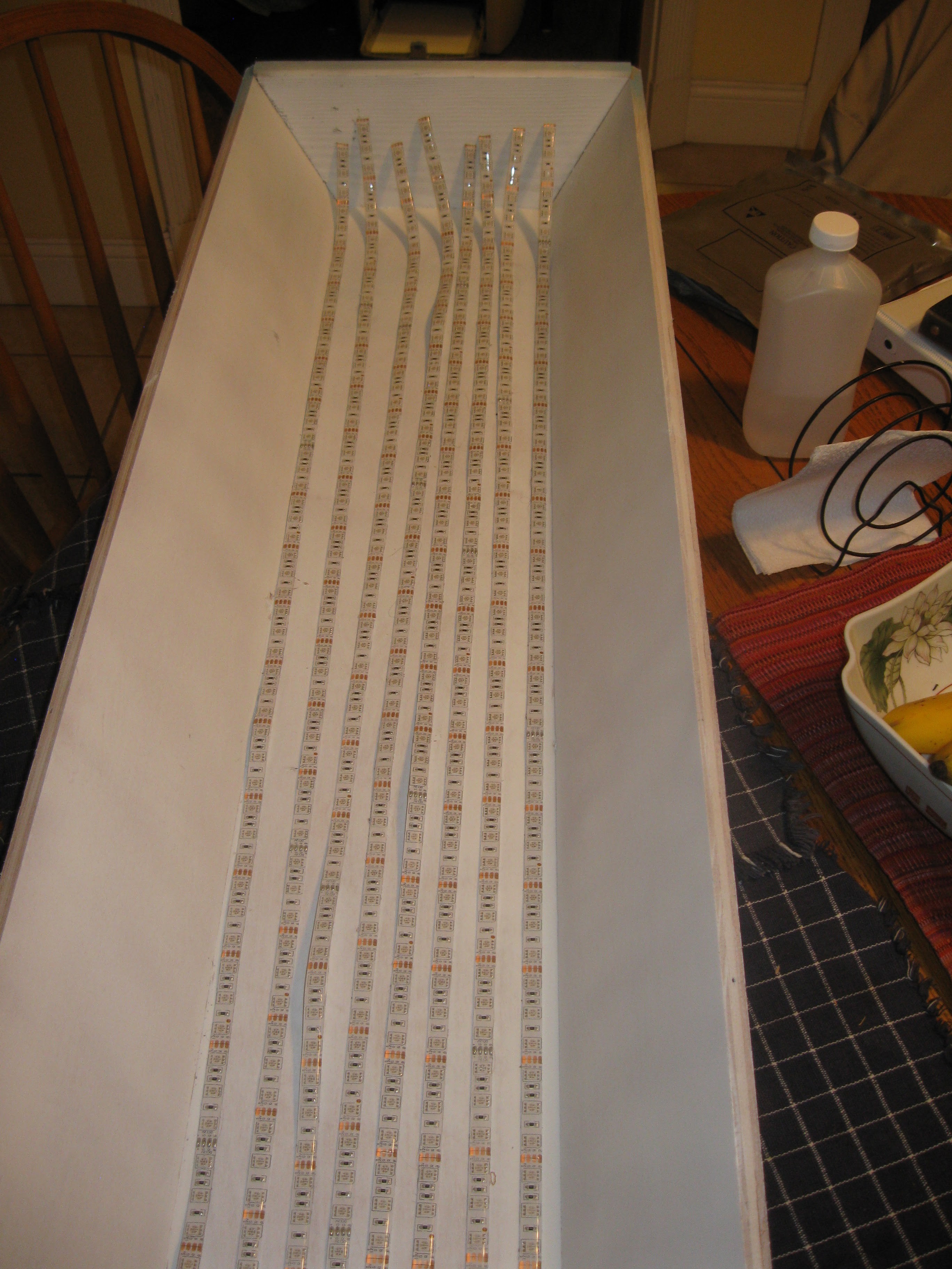
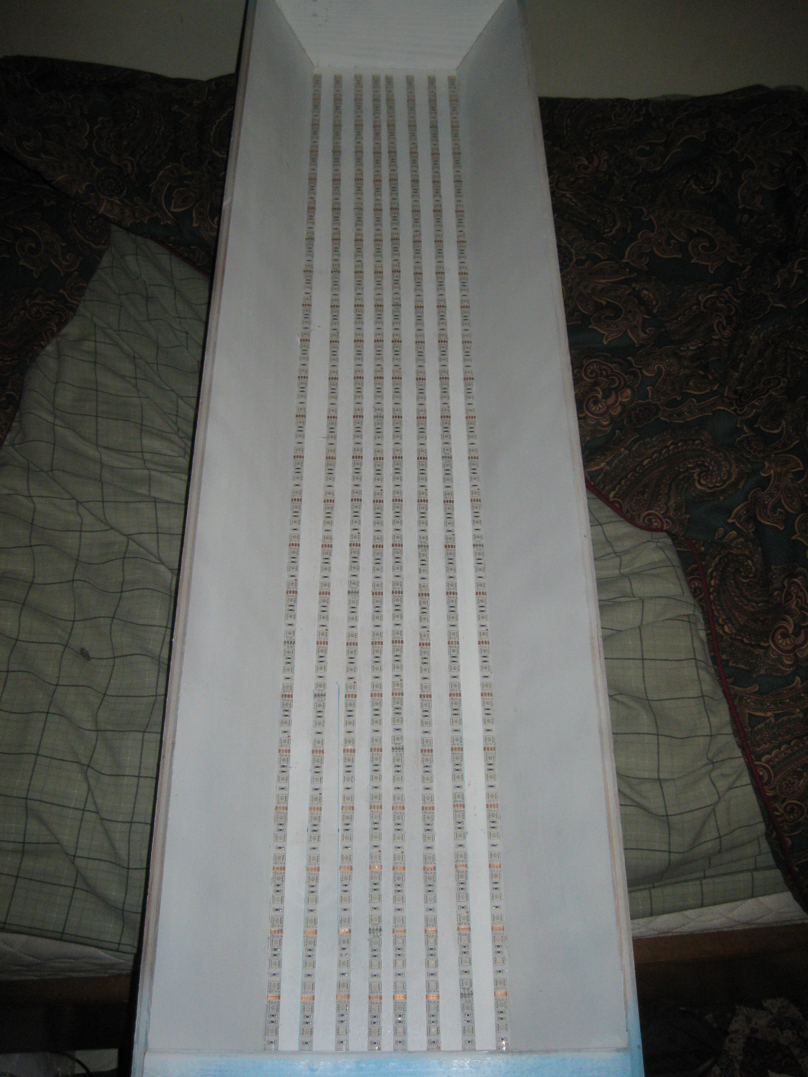
All strips in place along the marking. Eventually there will be strip on the outer sides and more in between. This light is the first prototype so I need to evaluate the LED strip I chose and figure out whether or not I need a different kind.
![]()
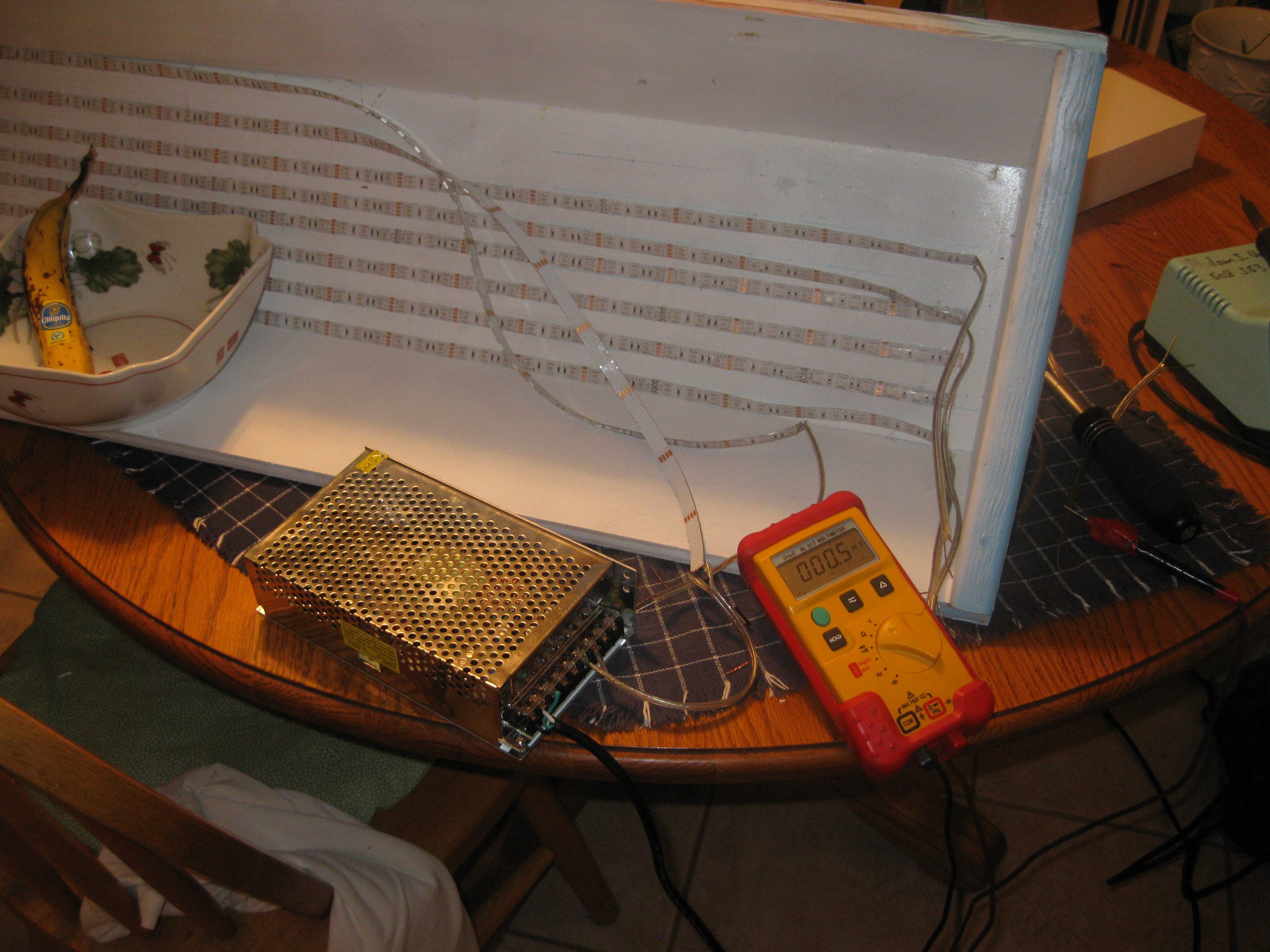
Next off was the process of soldering the LED strips to wires so they could be fed with the 12 volt 240 watt DCDC power supply I selected. As can be seen in the picture the adhesive on the LED strip isn't too great so they will be hotglued in place to help keep them attached to the light. As for the power-supply it is to be mounted on the front end of the light, holes will be drilled to get the wires through to the power supply.
![]()
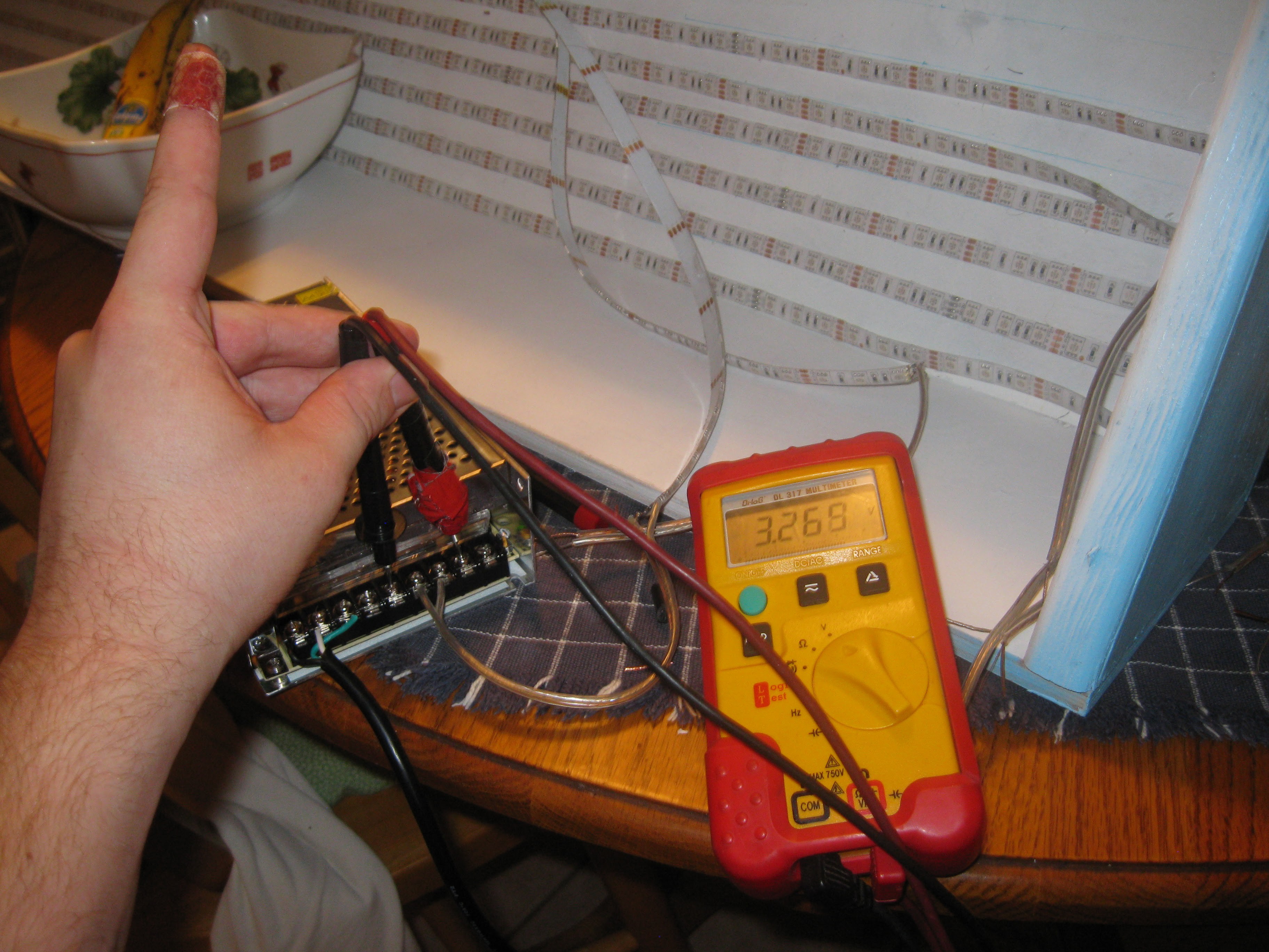
Upon wiring up the power supply I bought I discovered a problem with it. For some reason no matter what position the trim pot was turned to the PSU would only output 3.1-3.2 volts, which is completely wrong, its supposed to be in e range of 12 volts and then some. I've used similar PSUs to this one so I have no idea whats wrong other than it was mislabled as a 3.3v PSU or its defective. You can see in the picture that the PSU is not outputing the correct voltage, also notice that nasty cut on my finger, I don't recommend ripping apart AC Power cables with a pocket knife!!!!!
![]()
I contacted the seller and hopefully I'll be able to get a replacement soon. In the meantime a friend is gonna lend me a benchtop PSU to run the light until I get my new one. Stay tuned for more !
-
Beaglebone Green
09/17/2015 at 21:07 • 2 commentsThis week the Beaglebone Green arrived on Monday and I spent the whole evening setting it up and learning about it. The main application for HydroPWNics is a Java application packaged as an executable JAR file. The purpose of the Beaglebone Green in the HydroPWNincs system is to function as an embedded Linux environment for hosting a JVM to run said executable JAR. In that sense the Beaglebone is the master controller over the whole system all DyIO and module hubs in the system take instructions and send feedback to the Beaglebone running the JAR.
Beaglebone Green and Packaging unboxed and booted:
![]()
![]()
First thing I did upon booting up the BBG was obtaining SSH access. By default the BBG's IP address is 192.168.7.2, to SSH in you must first SSH as root, the root password by default is blank. The BBG ships with a build of Debian for the ARM, this makes installing software and working with it really easy, almost no different from dealing with a regular Debian based system. Once I was SSHed in as root I created a new user for myself for development purposes, and a new user for the HydroPWNics application. Creating new users was just like on my server which runs Ubuntu Server (also a Debian based OS), using a Debian based distro really just makes it easier.
On to Java, I first installed the Oracle JDK via the apt-get package manager, installed with no frills and worked right away, the only problem is that the JDK in the package repository was a very old release. To support BowlerStudio on which HydroPWNics is written, the latest JDK is required. To install the latest ARM Java 8 JDK release I hade to manually install it with the following process:
- First on your local machine download the latest Java 8 package for Linux ARM v6/v7 Hard Fload ABI found here:http://www.oracle.com/technetwork/java/javase/downloads/jdk8-downloads-2133151.html
- Open up a Terminal session on your local machine
- Copy the Java archive to the home directory of the root user on your Beaglebone Black/Green. Open up a Terminal session on your local machine and type with the following command:
sudo scp /path/to/java/archive root@192.168.7.2:/path/to/user/home - Once the file has finished copying over to the home directory of your user account on the Beaglebone open up a Terminal session and SSH into the Beaglebone
- Once inside the SSH session on the Beaglebone make sure you are in he home directory and unpack the java archive:
cd /~ gunzip jdk-8-linux-arm-vfp-hflt.tar.gz - Copy Upack the tar into the /usr directory:
sudo tar xf jdk-8-linux-arm-vfp-hflt.tar -C /usr - Next update the Java path by adding the following lines to the .bashrc file
sudo nano ~/.bash_profileAdd the follownig to the ~/.bash_profile and save it
#### JAVA 1.8.0 #######################
    export JAVA_HOME=/usr/jdk1.8.0_60
    export PATH=$PATH:$JAVA_HOME/bin
 #### JAVA 1.8.0 #######################
Then run
source ~/.bash_profile - Finally to test the install and check the Java version:
java -versionIt should print back something like this:
java version "1.8.0_60"
Java(TM) SE Runtime Environment (build 1.8.0_60-b27)
Java HotSpot(TM) Client VM (build 25.60-b23, mixed mode)
So yeah after some hacking away at the terminal Java is installed on the Beaglebone. Now since this project is utilizing BowlerStudio and it would make sense to be able to pull and build BowlerStudio from the git repo right on the Beaglebone. In order to build BowlerStudio in the shell from source, not only is Java required but also Maven and Gradle, I will go over the process I went to install them below:
Installing Maven 3.3.3 on the Beaglebone Green:
- Open a Terminal session
- SSH into the Beaglebone using user account.
- Now download the latest build of Maven 3.3.3
cd /tmp sudo wget http://apache-mirror.rbc.ru/pub/apache/maven/maven-3/3.3.3/binaries/apache-maven-3.3.3-bin.tar.gz - Now to unpack the archive, create the install directory, and move the contents of the archive tot he directory
sudo tar -xvzpf apache-maven-3.3.3-bin.tar.gz sudo mkdir -p /opt/maven/3.3.3 sudo mv apache-maven-3.3.3/* /opt/maven/3.3.3/ sudo ln -s /opt/maven/3.3.3/ /opt/maven/current - Now to add the proper PATH, open your bash profile:
- Test Installation and Check Version
mvn -version
sudo nano ~/.bash_profileAdd the following to the File below the Java entry :#### MAVEN 3.3.3 ######################### export MAVEN_HOME=/opt/maven/current export PATH=$PATH:$MAVEN_HOME/bin #### MAVEN 3.3.3 #########################Then runsource ~/.bash_profileInstalling Gradle on the Beaglebone Green
- Open a Terminal session
- Access the Beaglebone over SSH under the user account you created earlier inthe tutorial
ssh your-username@192.168.7.2 - Now download the latest Gradle
cd /tmp sudo wget https://services.gradle.org/distributions/gradle-2.7-all.zip - Now to unpack the archive, create the install directory, and move the contents of the archive tot he directory
unzip gradle-2.4-all.zip sudo mkdir -p /opt/gradle/2.4 sudo mv gradle-2.4/* /opt/gradle/2.4/ sudo ln -s /opt/gradle/2.4/ /opt/gradle/current - Now to add the proper PATH, open your bash profile:
sudo nano ~/.bash_profileAdd the following entry after the others:
#### GRADLE 2.7 ########################### export GRADLE_HOME=/opt/gradle/current export PATH=$PATH:$GRADLE_HOME/bin #### GRADLE 2.7 ########################### - Then run:
source ~/.bash_profile - Lastly check test the installation and check version:
gradle -version
So After all that the Beaglebone Green has the latest Java 8 for ARM, Gradle, and Maven. Immediately after getting everything isntalled and setup I set out to build BowlerStudio from source. Everything was going fine until it needed to find the JavaFX libraries, it couldn't seem to find them despite Java 8 for ARM supporting it natively. I need to do a bit more investigating to figure out this bug. Stay tuned for more updates on the project, the next deadline is approaching so expect more updates this week/weekend!!!!
-
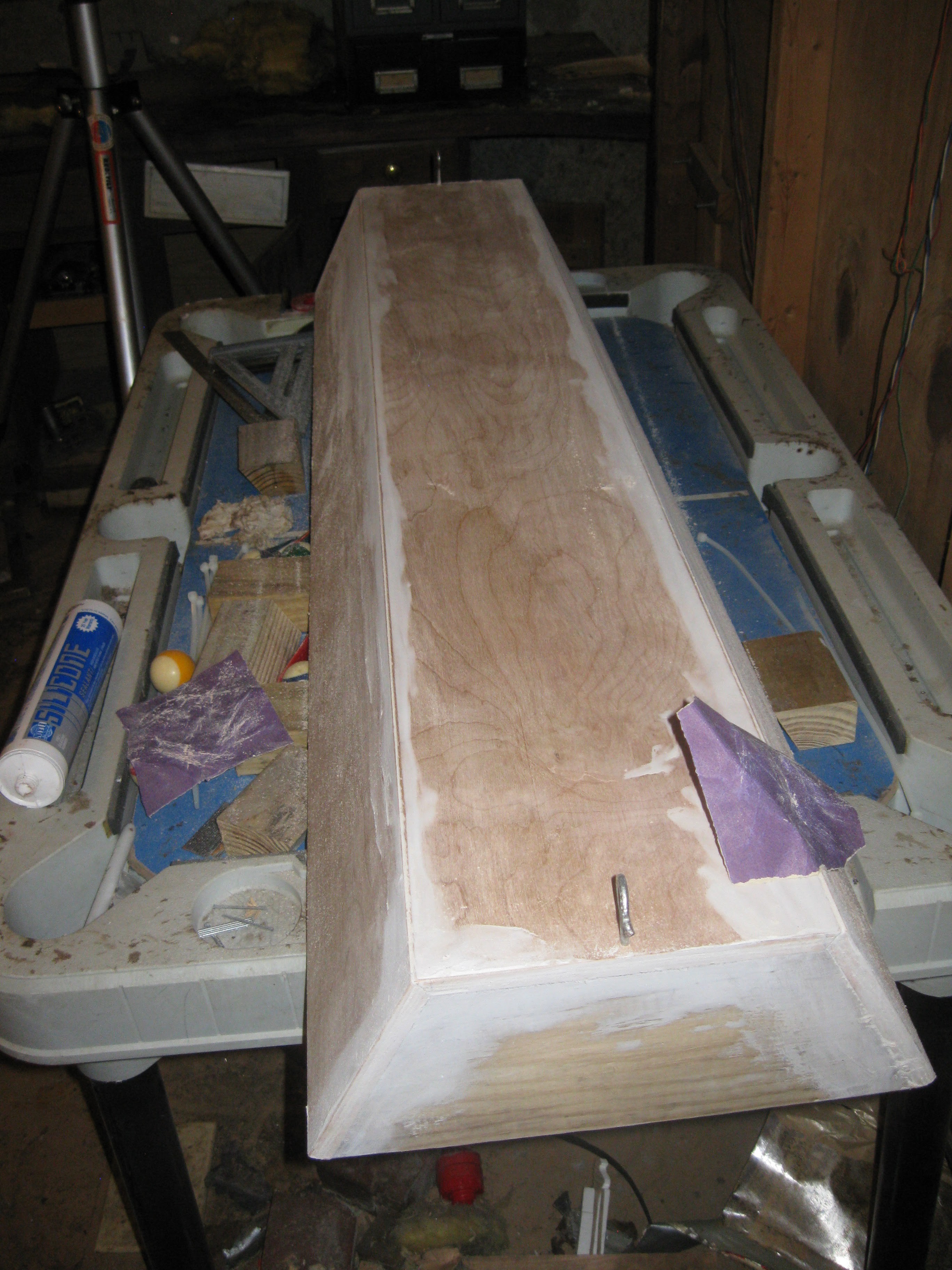
More Light Progress and Water Circulation Test
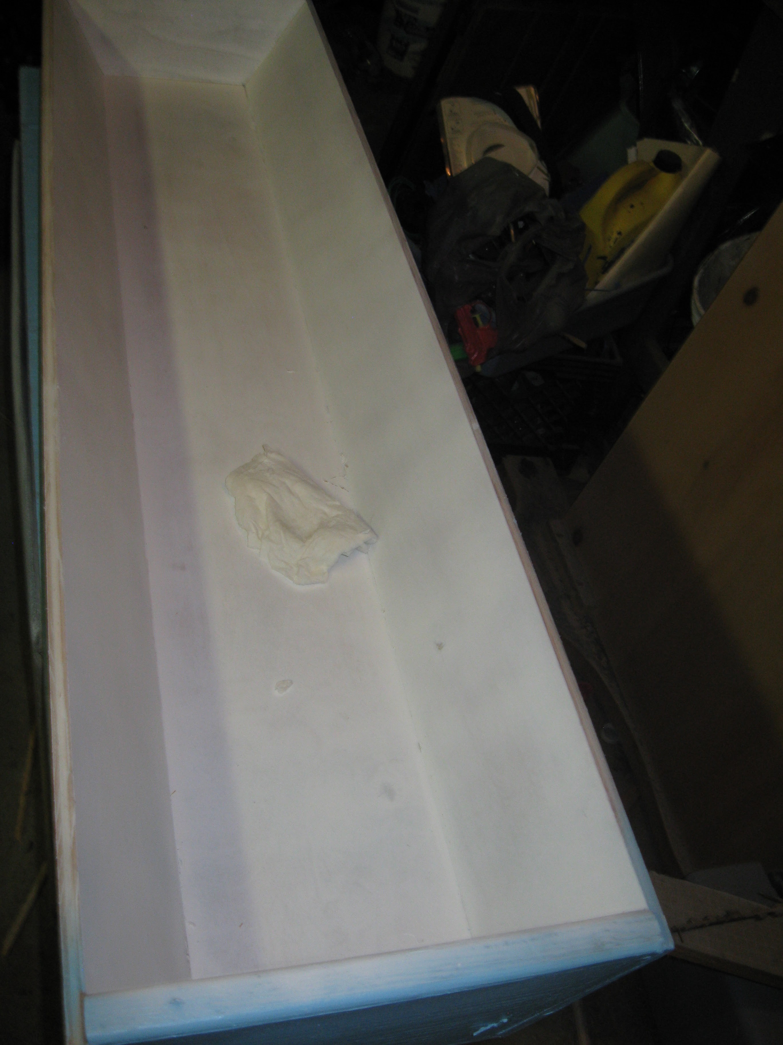
09/13/2015 at 08:38 • 0 commentsThursday of this past week I got a bit more done. I sanded and painted the grow light casing (see previous log) smooth for painting, and painted it. I also conducted a circulation test of the NFT system in the basement. First off the light, I started by sanding the edges and caulking down with sand paper by hand. I tried to sand it all down smooth but the caulking is tough stuff, I did the best i could before cleaning it with a dam rag for painting.
Sanding the grow light casing:![]()
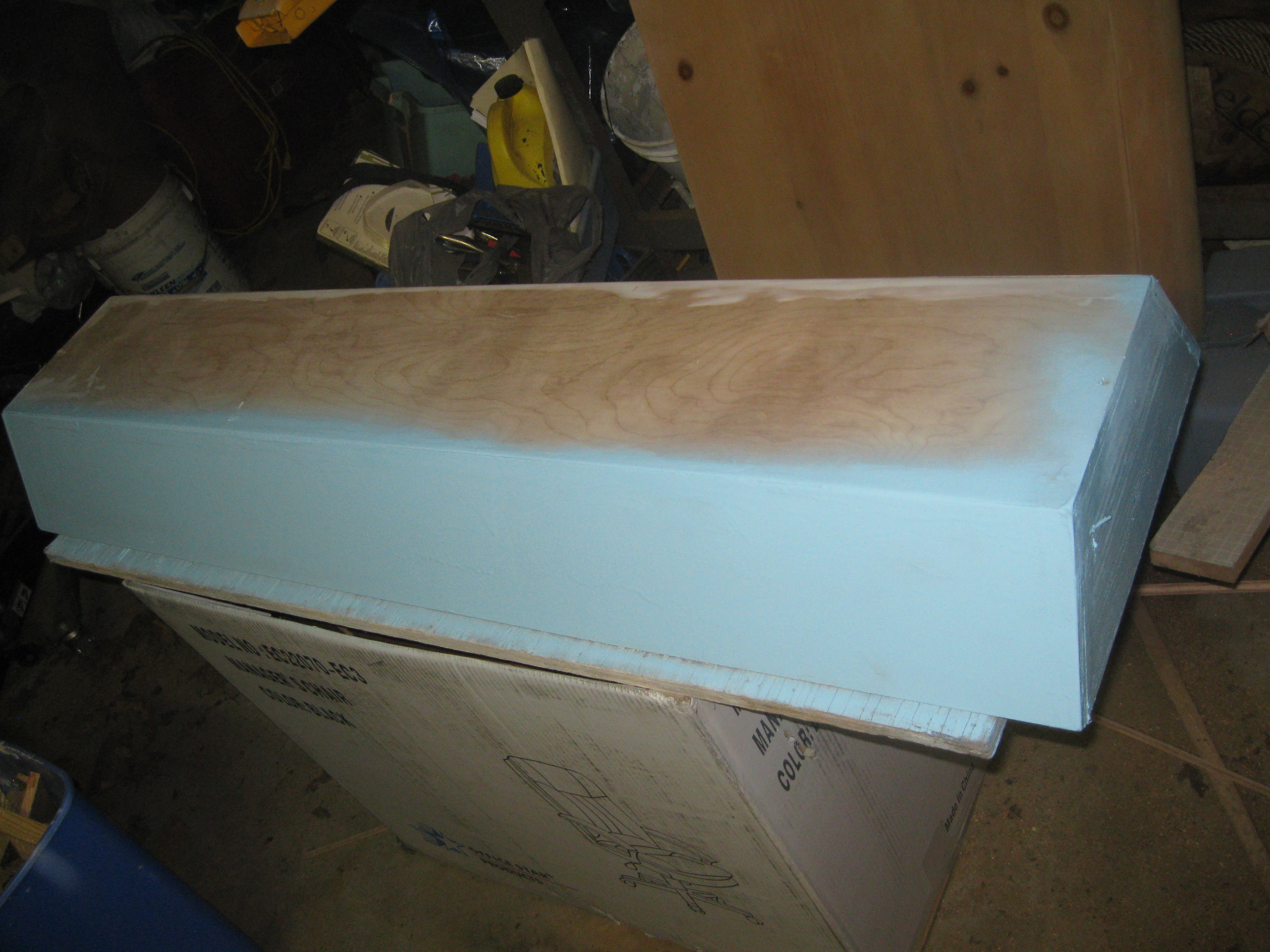
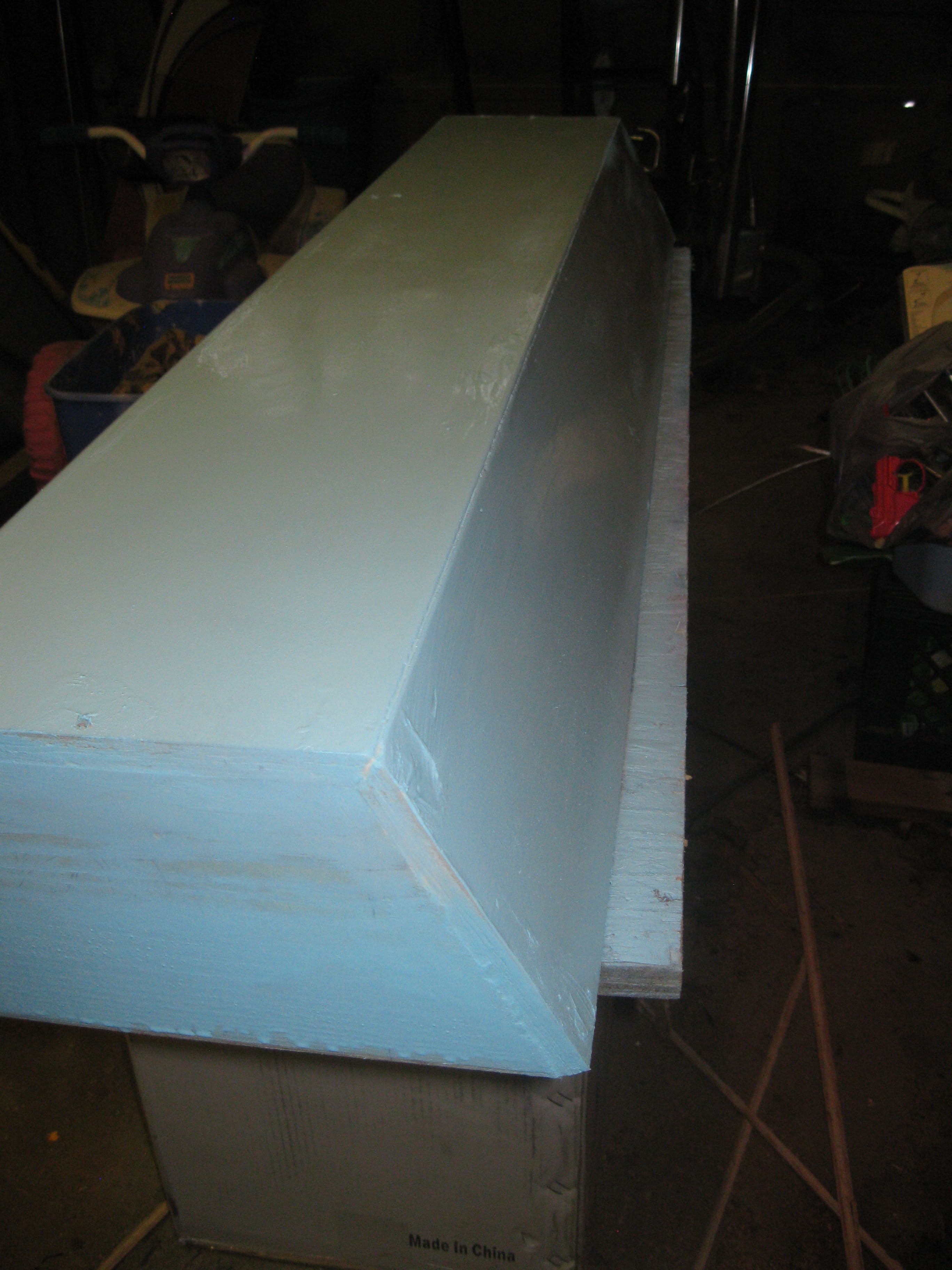
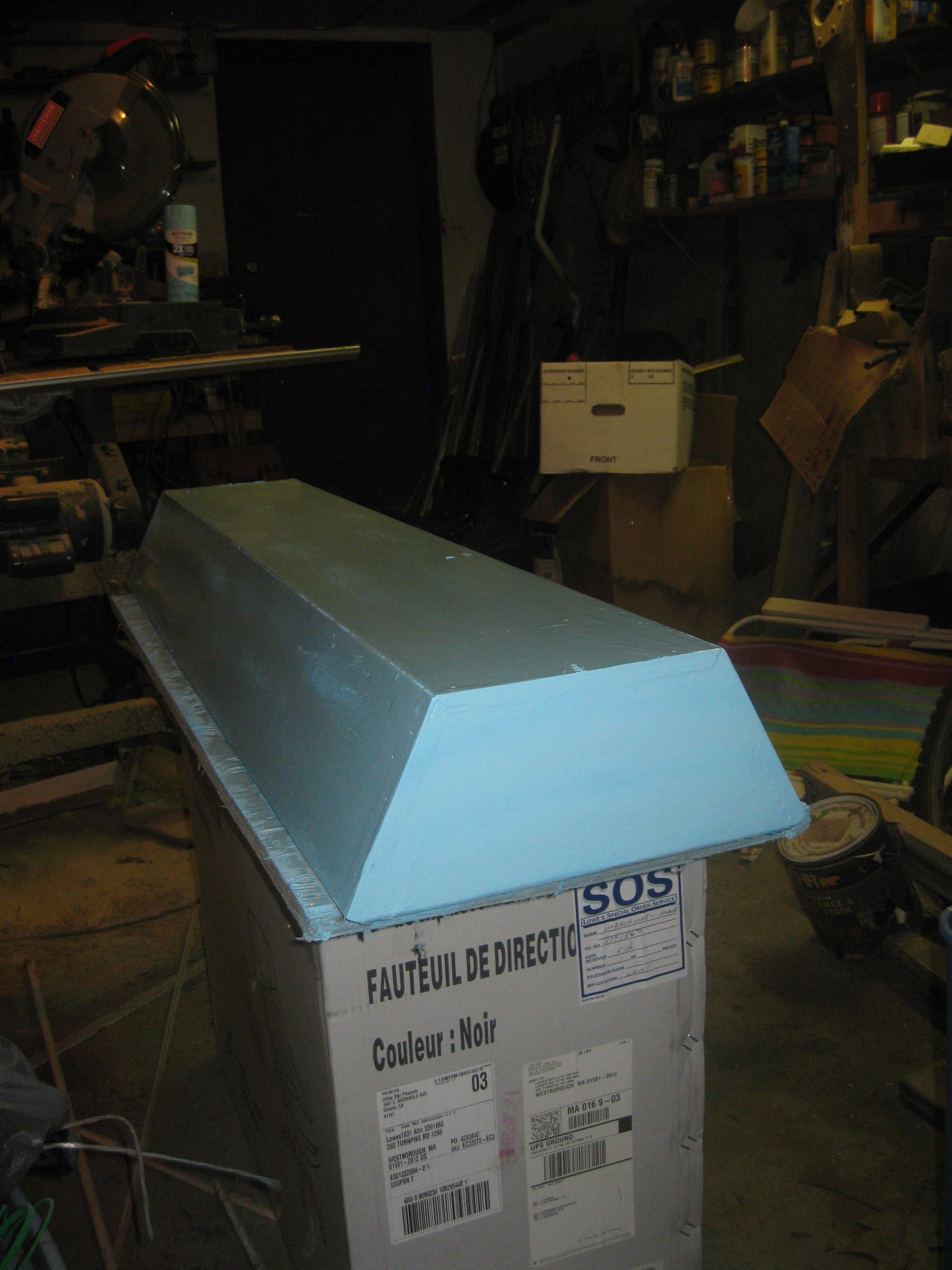
After I completed sanding and cleaning the dust off I brought the case into the garage for painting. I set up a simple table with a piece of plywood and an old card board box for painting. I painted in stages doing multiple coats over a few hours, this is so the paint doesn't drip and form drip marks all over the surface. I used rustoleom spray paint since its good on wood/plastic/metal and its cheap.
![]()
One side and end painted, with the top and other side to go.
![]()
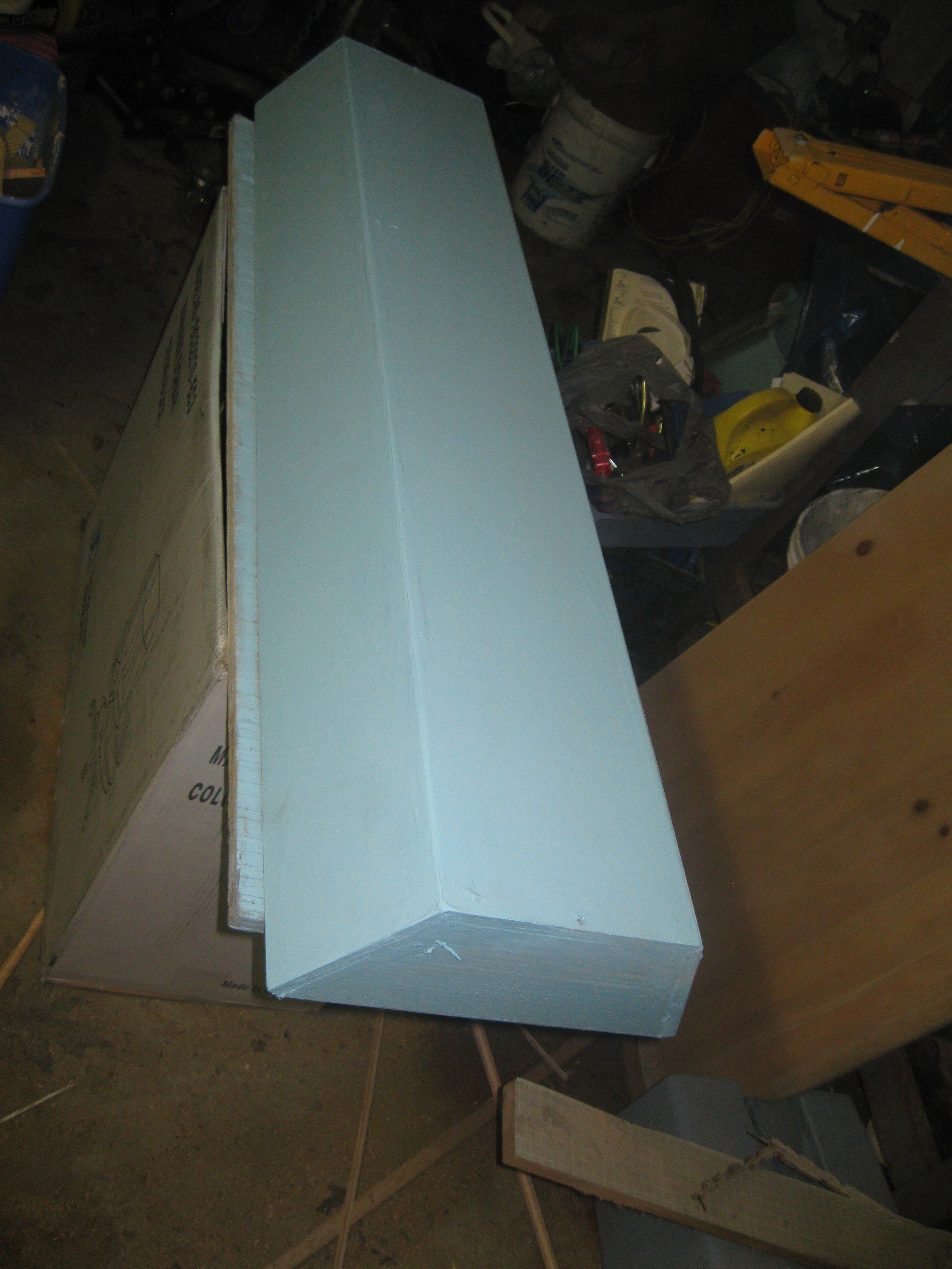
Top and and one side painted with one coat.
![]()
![]()
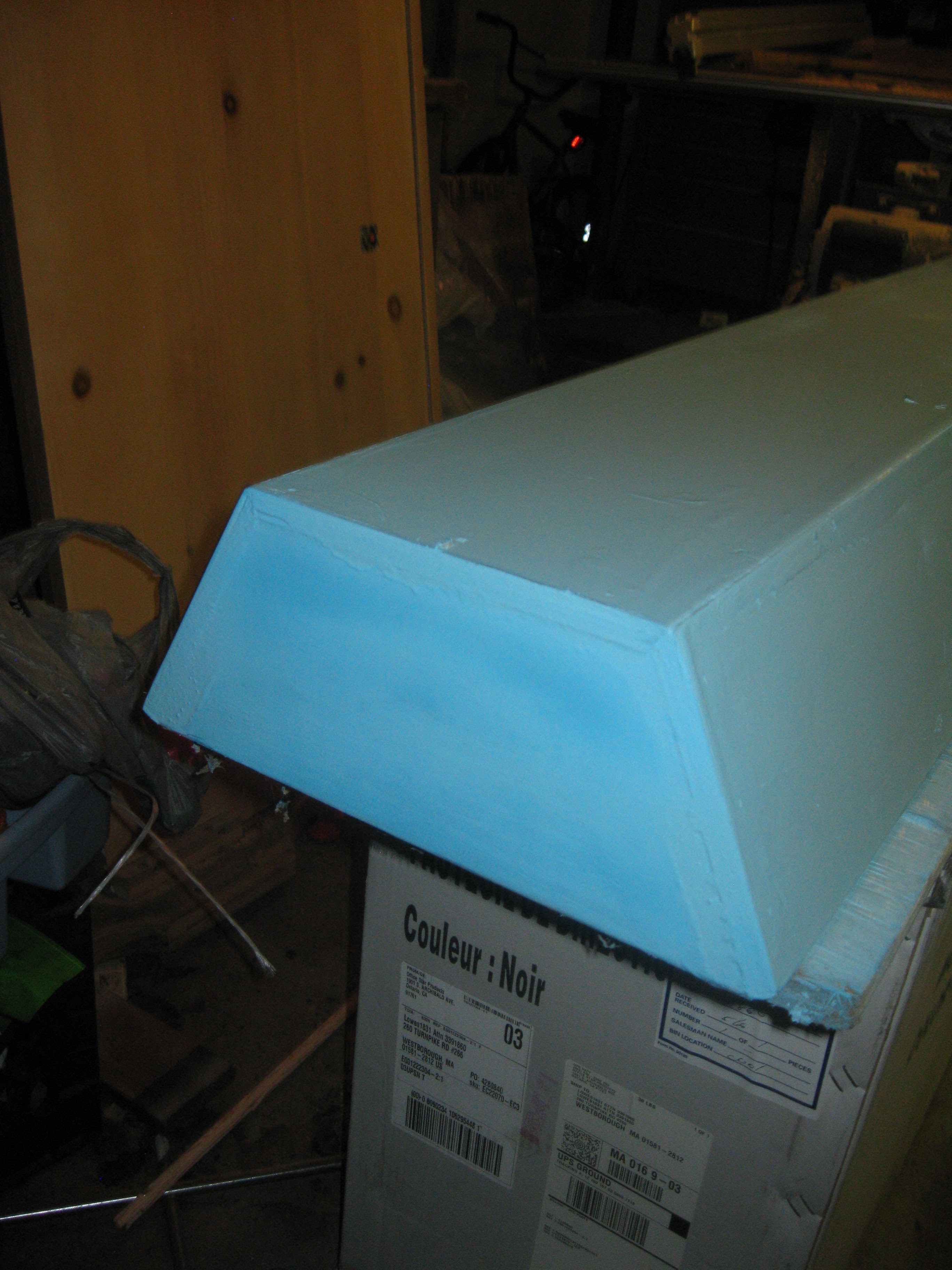
Other side painted, this color is very nice the pictures really don't do it justice!
![]()
Opposite end painted with first coat.
![]()
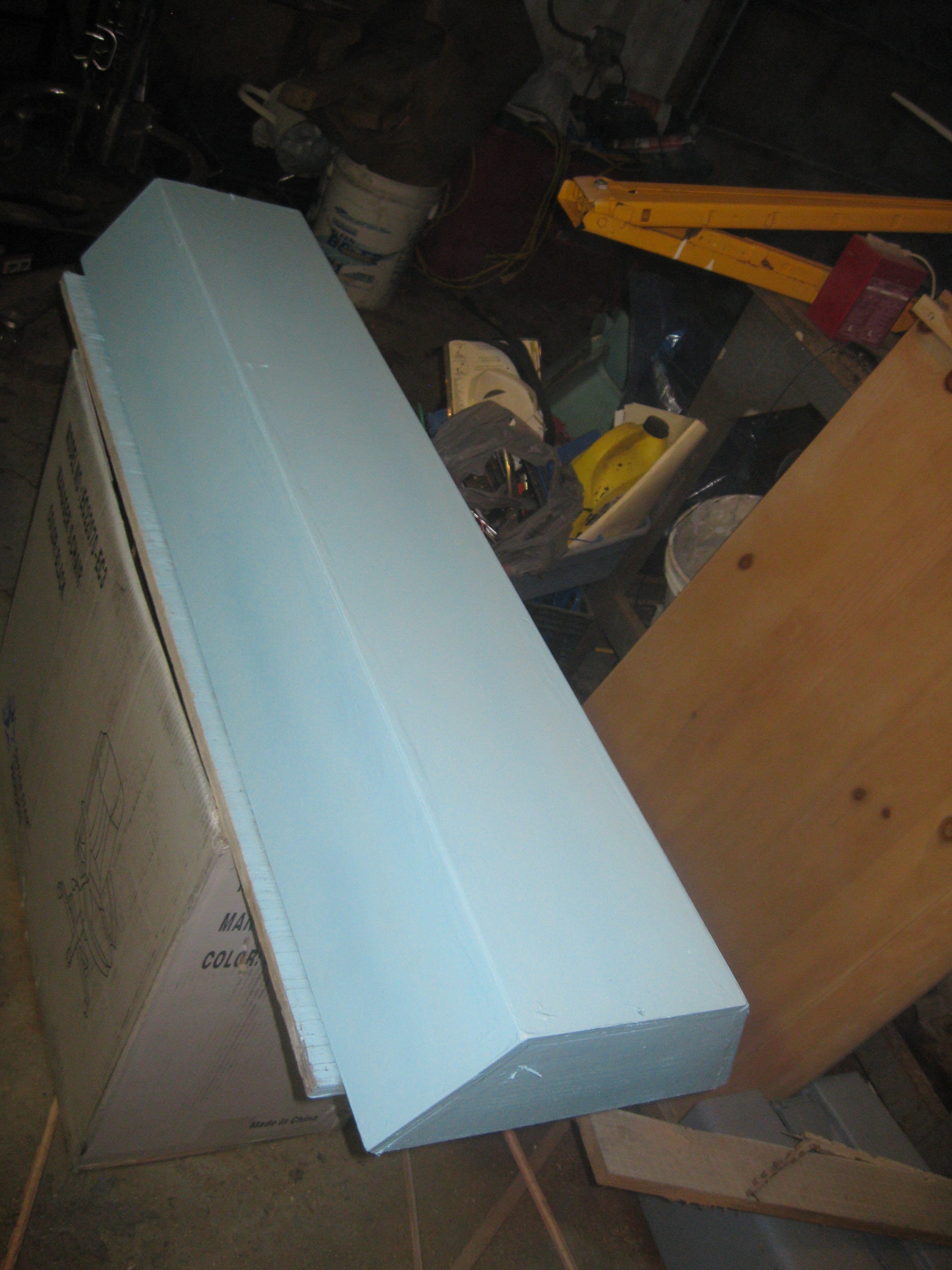
Second and final coats of paint:
![]()
![]()
![]()
![]()
![]()
Painting tool about three coats and I didn't even use up all the paint in the can. The first two coats were heavier than the third, overall it came out pretty good. I need to do some more painting on the inside before I install the lights. Before I was thinking of plating the inside using tin foil or with a reflective mylar space blanket, to simplify things I will be painting the inside white. The color white should be reflective enough given that almost the entirety of the inside of the case will be lined with LED strip.
Moving on with the NFT system test. Before getting too excited and moving all my cramped plants into the new grow system I decided to conduct a test of the pump circulation system. I wanted to make sure the pump I am using can handle pumping from the reservoir into the input manifold. Setting up the NFT system with water for the first time is sort of a process, first I'll talk about the setup/function and what I found out about my chosen design.
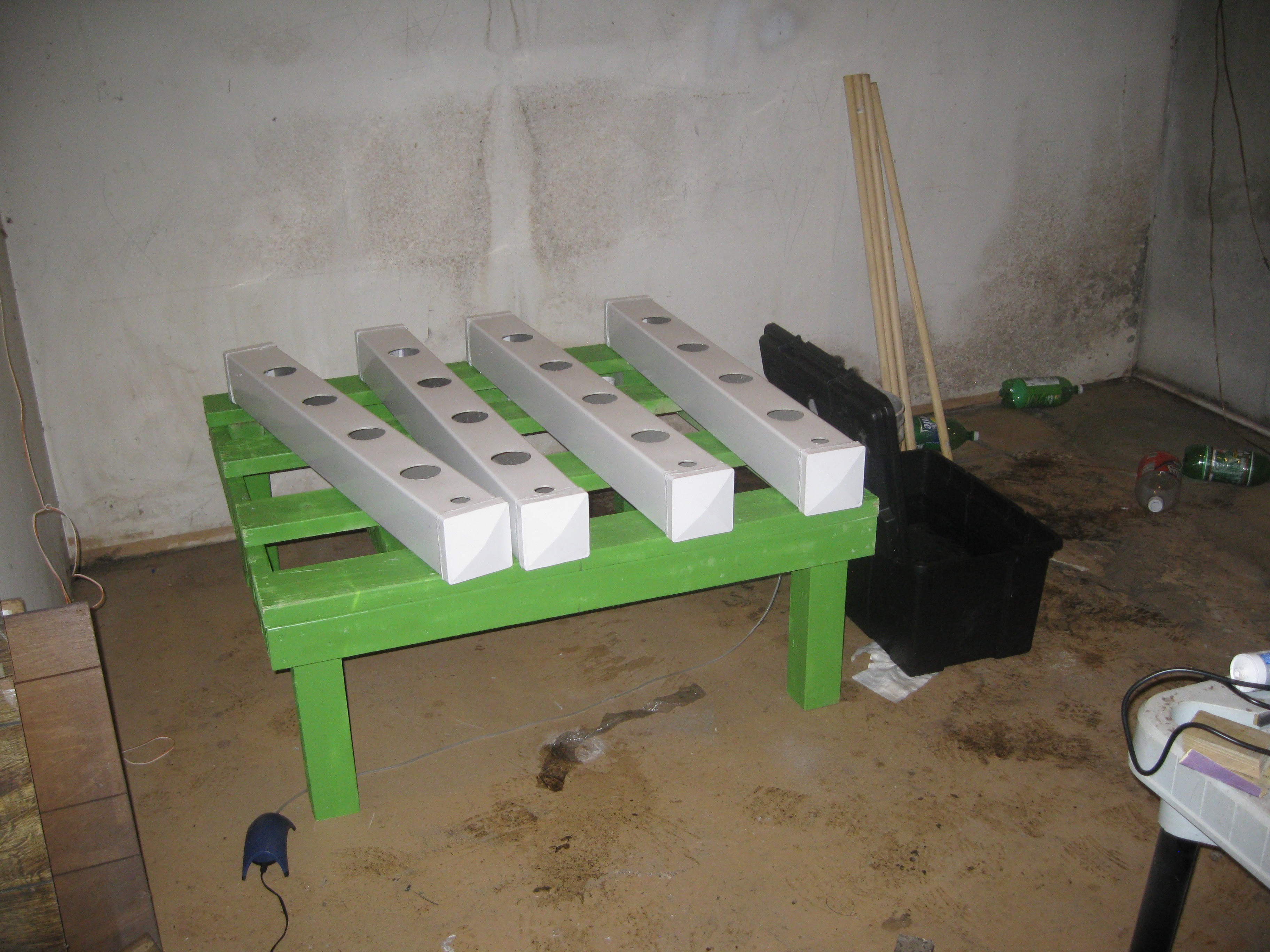
The setup as left after the silicone sealing of the end caps. It was good it was still mostly dismantled, installing the reservoir in place beneath the until requires lifting the frame, its a lot easier with everything removed.
![]()
Flow rate sensor removed from pump tubing assembly and installed to the input manifold. The fitting on the end of the flow rate sensor adapts from 1/2" threads to a 1/2" barbed end for attaching to the tubing on the submersible pump.
![]()
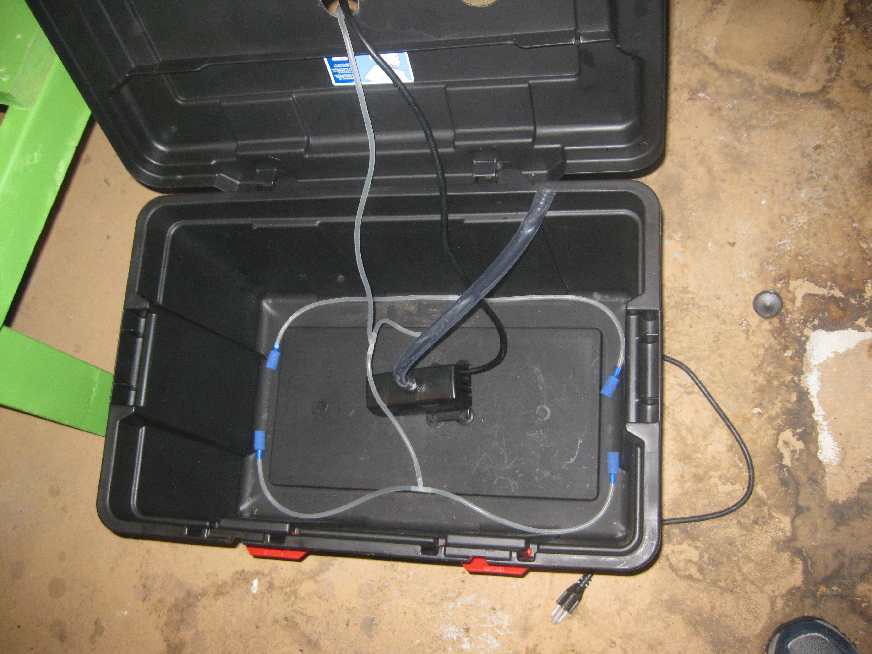
To get things started I began with setting up the reservoir internally, an airstone in each corner almost and the pump centered in the middle, secured to the bottom with suction cup feat. The tubing for the airstones, pump power cord, and pump tube all fit through the same hole in the top.
![]()
Next I filled the reservoir with 5 gallons of water, everything inside got swished around.Later a better method for securing the pump and airstones will have to be worked out, possible using silicone as a glue to secure the tubing in place on the bottom. The reservoir has to be filled before hand at the moment since there isn't an input pipe yet, later I plan to add another 1 1/4 " pipe for adding more water/nutrients/boosters to the reservoir.
![]()
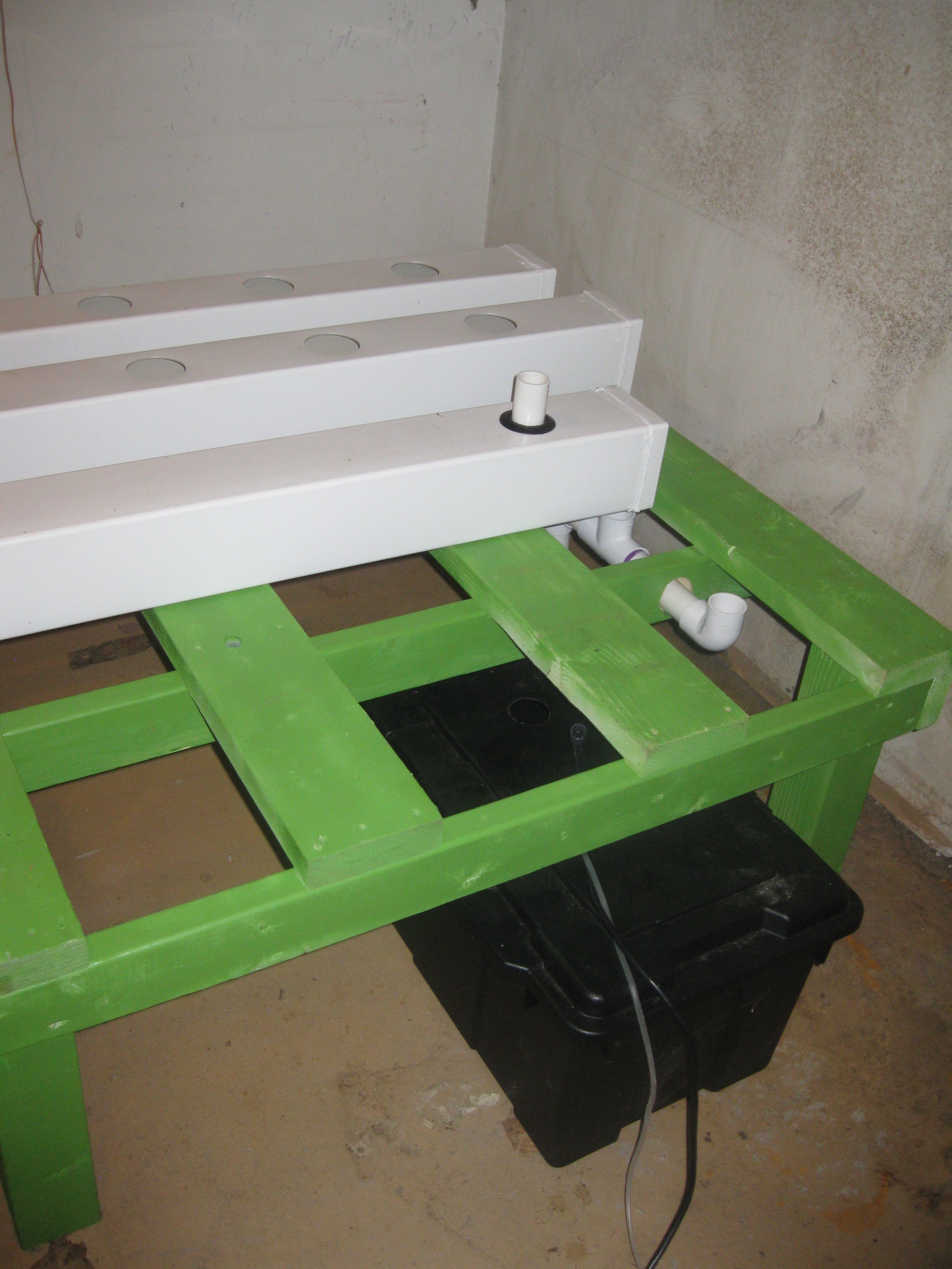
Next I slid the reservoir beneath the frame. Since the drain manifold is built into the frame the frame needs to be lifted up to slide the reservoir underneath.
![]()
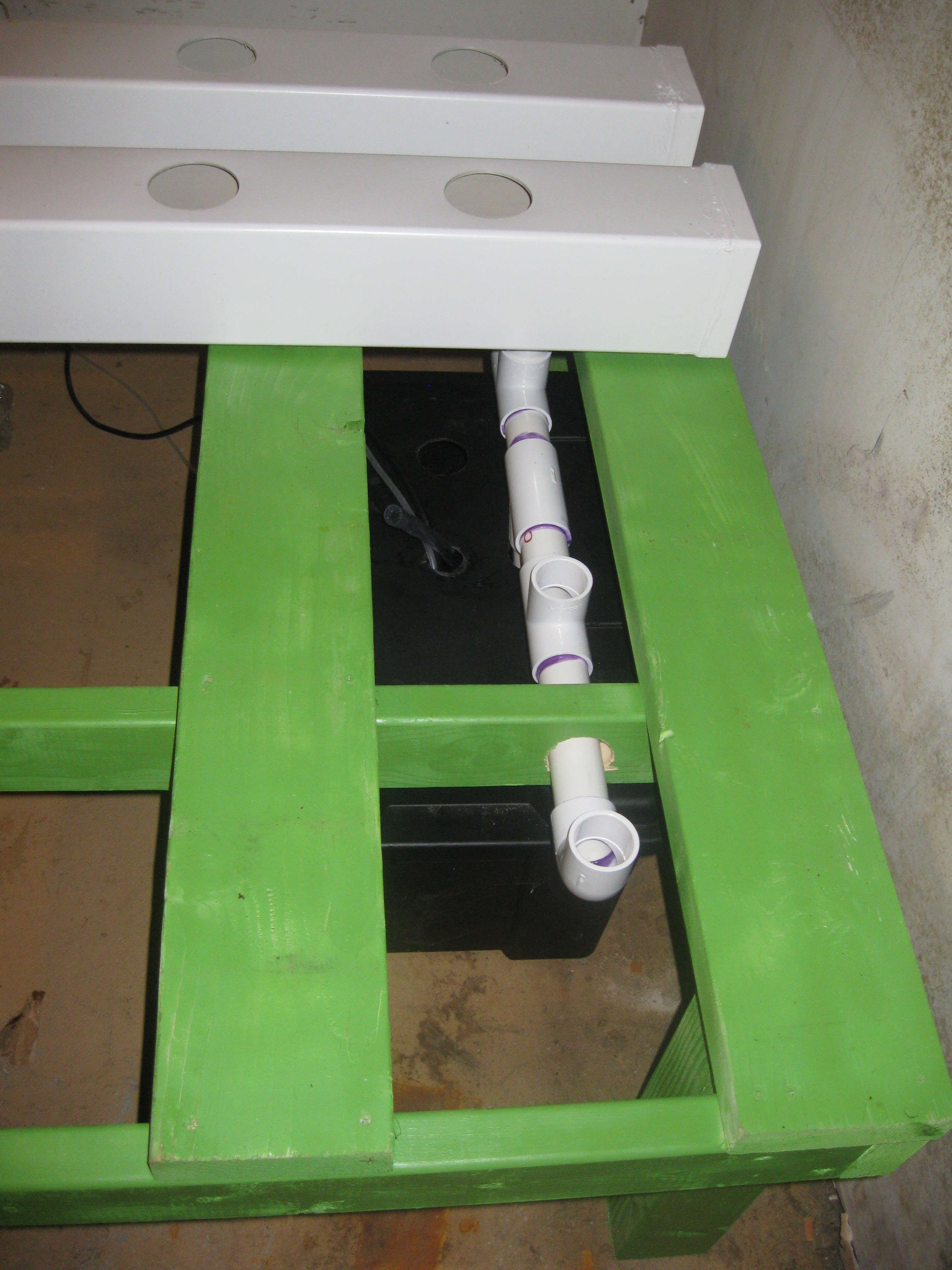
Reservoir installed into place, with the drain manifold exit protruding directly through the hole cut for it on the top of the reservoir.
![]()
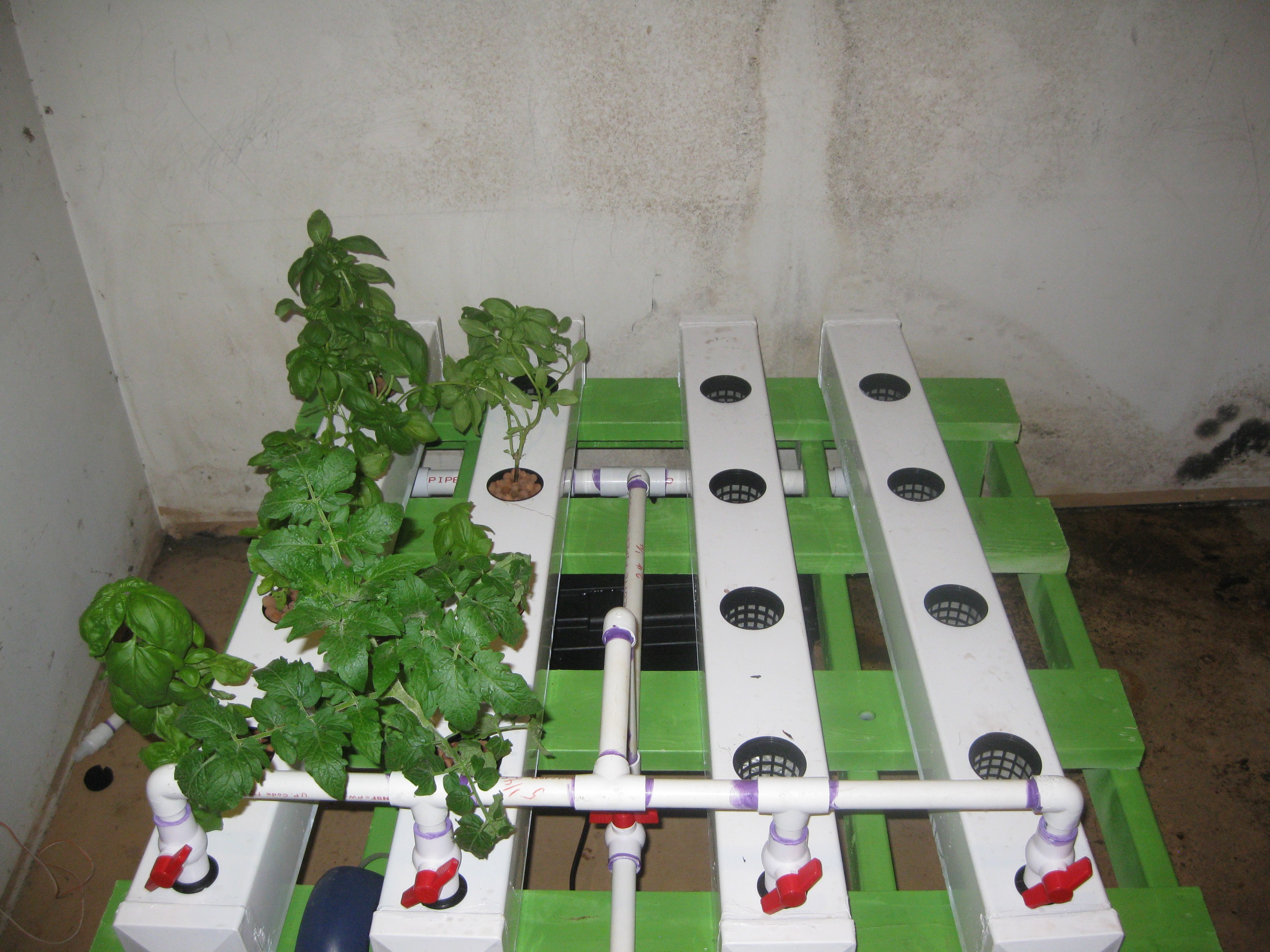
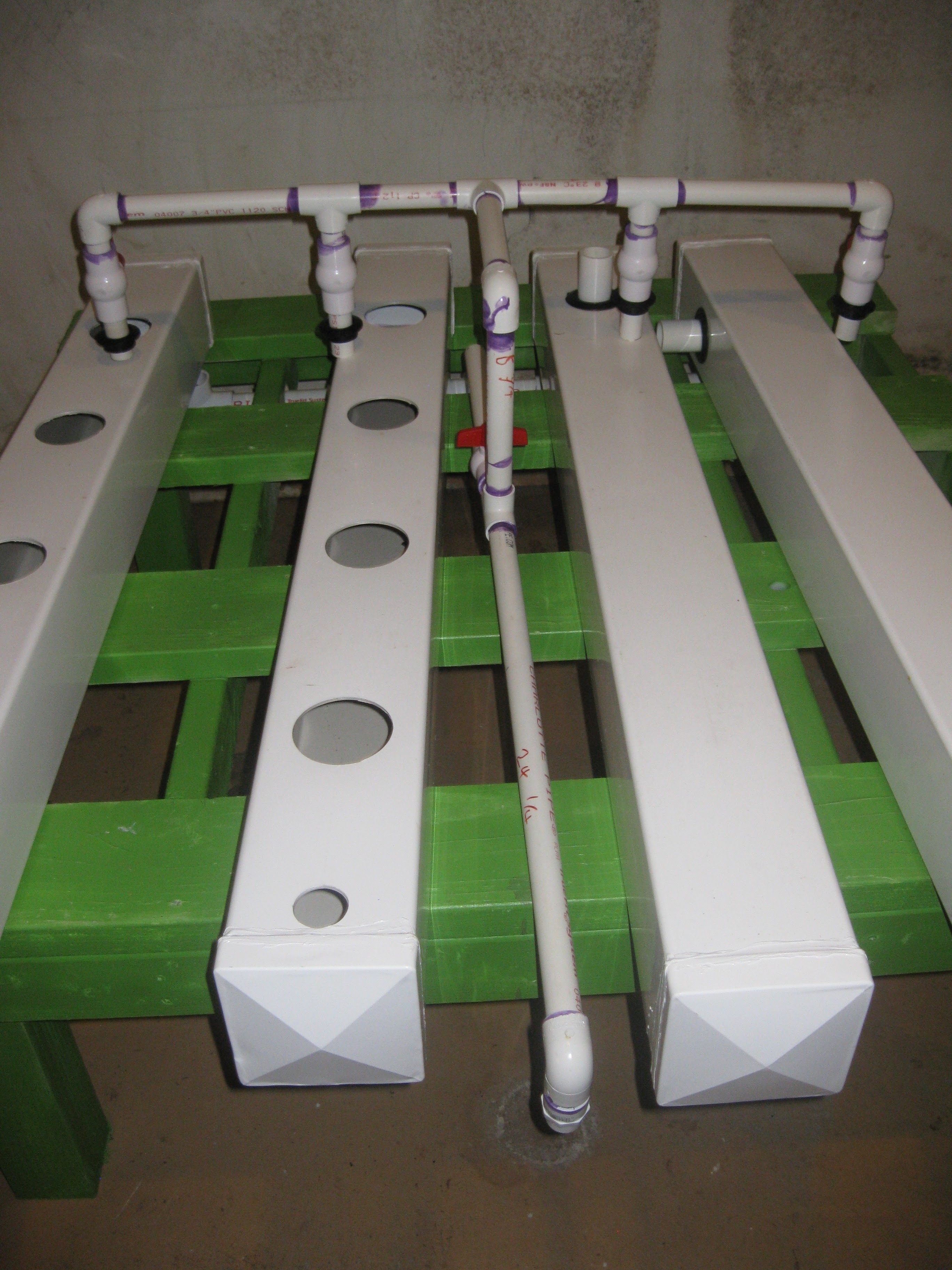
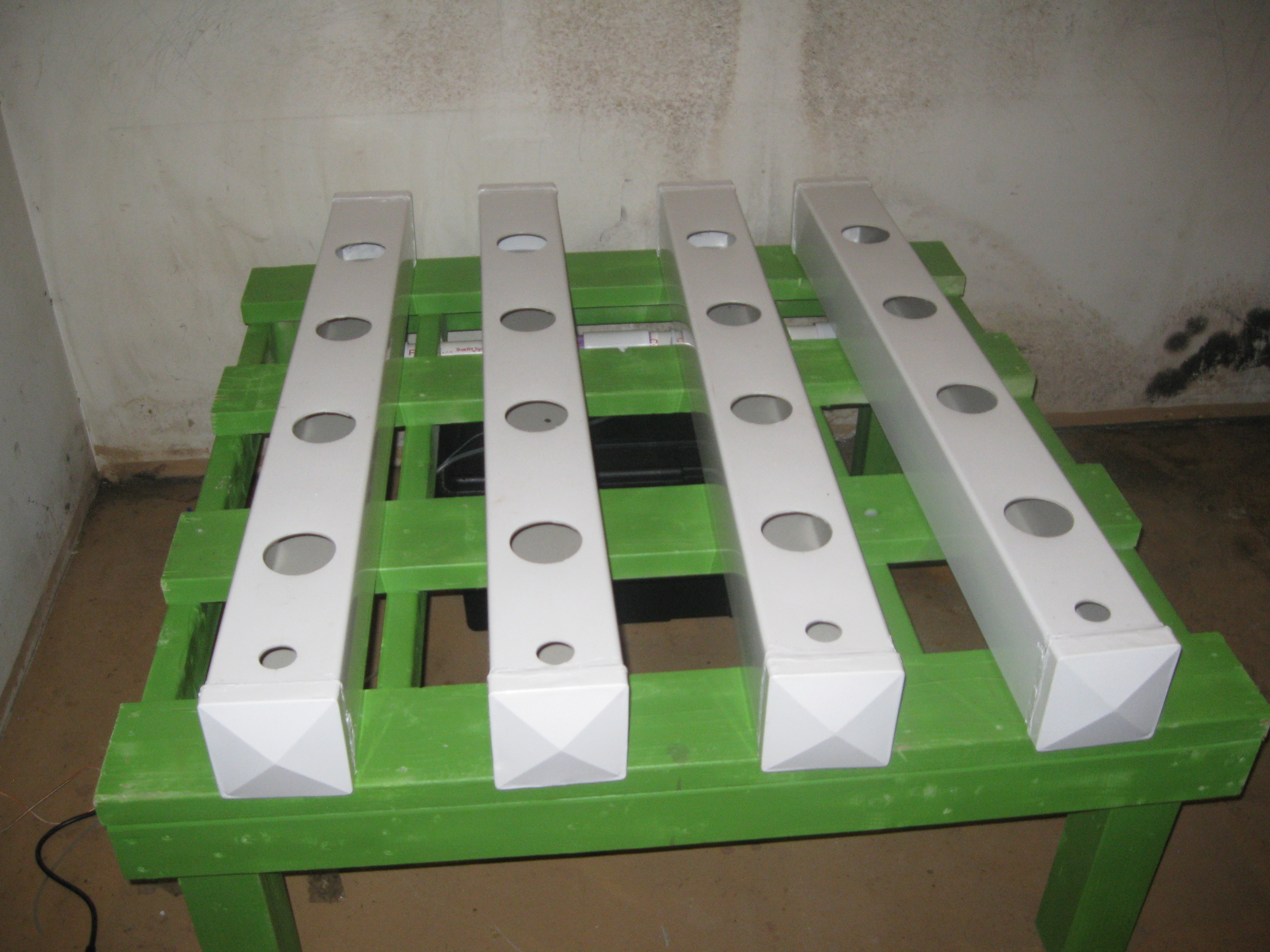
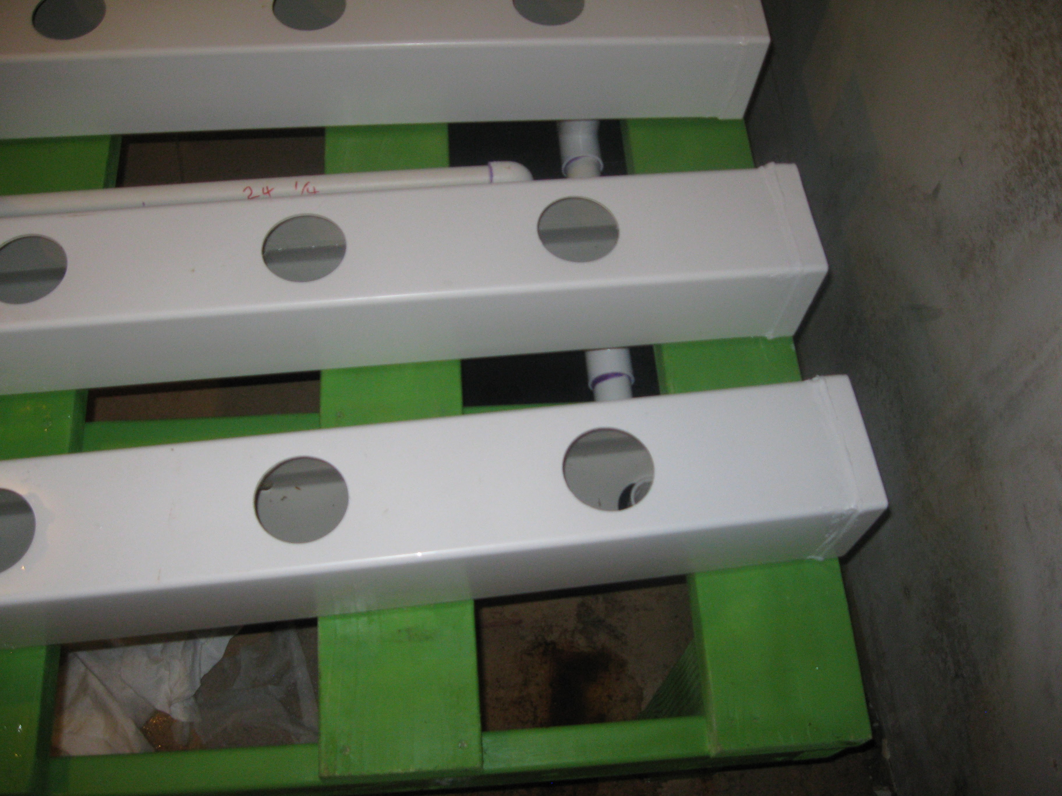
All four fence post grow rows installed into place after installing the reservoir. The next step was installing the input manifold and connecting it to the pump. After the input manifold was in place, valves on 3 of the four rows were closed before starting the pump, each row disabled at the start were enabled one at a time starting after the first row was filled and running into the drain manifold.
![]()
Water inside the first two rows
![]()
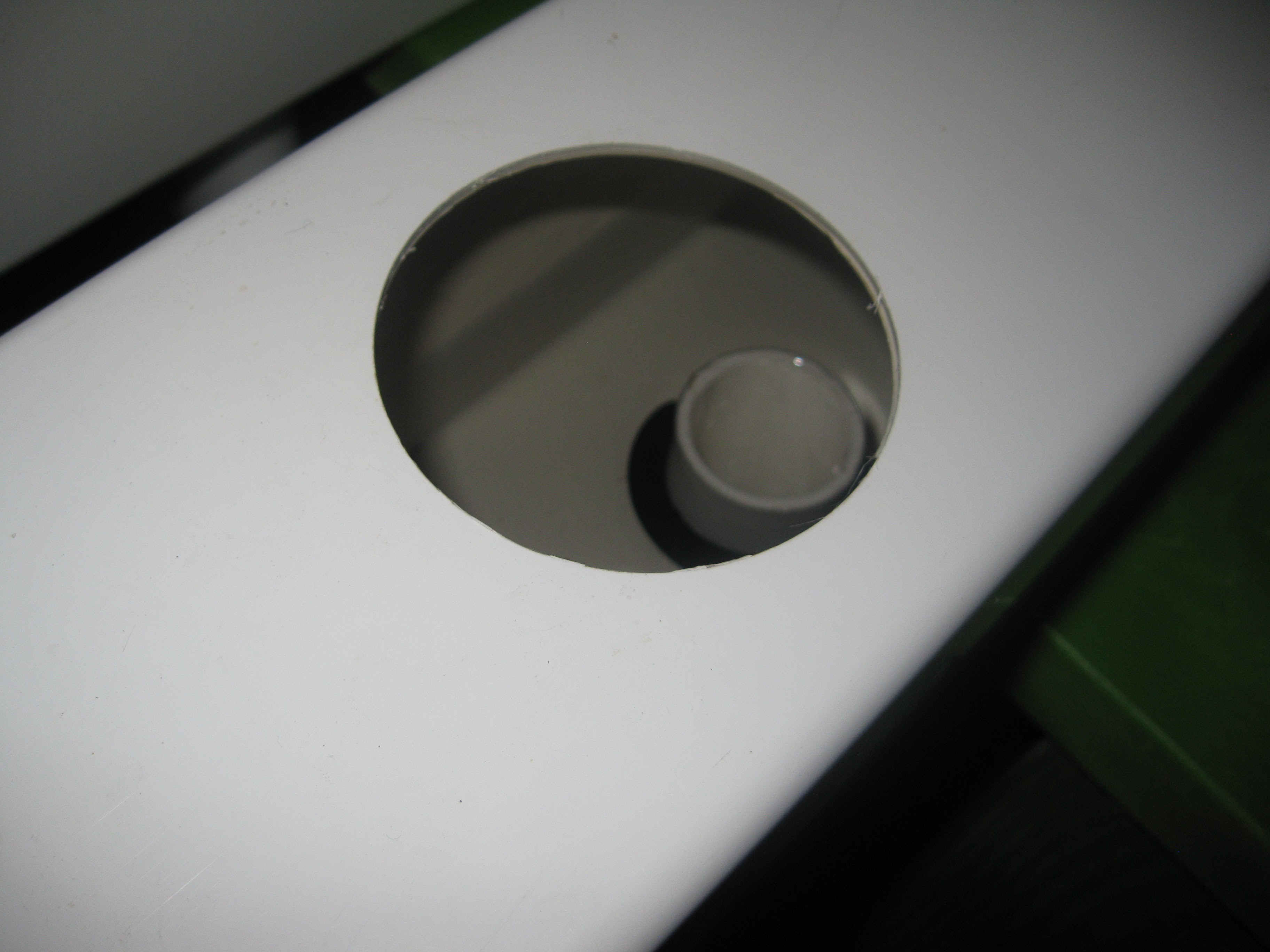
Close up of the water draining into the drain manifold on one of the rows.
![]()
After attempting to get all four rows filled with water, I discovered a problem. It seemed the pump was too weak to pump the water into the manifold. After some investigation and testing different rows by opening and closing the valves, I determined that the pump only has enough power to run half the system. A larger pump will be needed to get the system up and running but its not the end of the world.
![]()
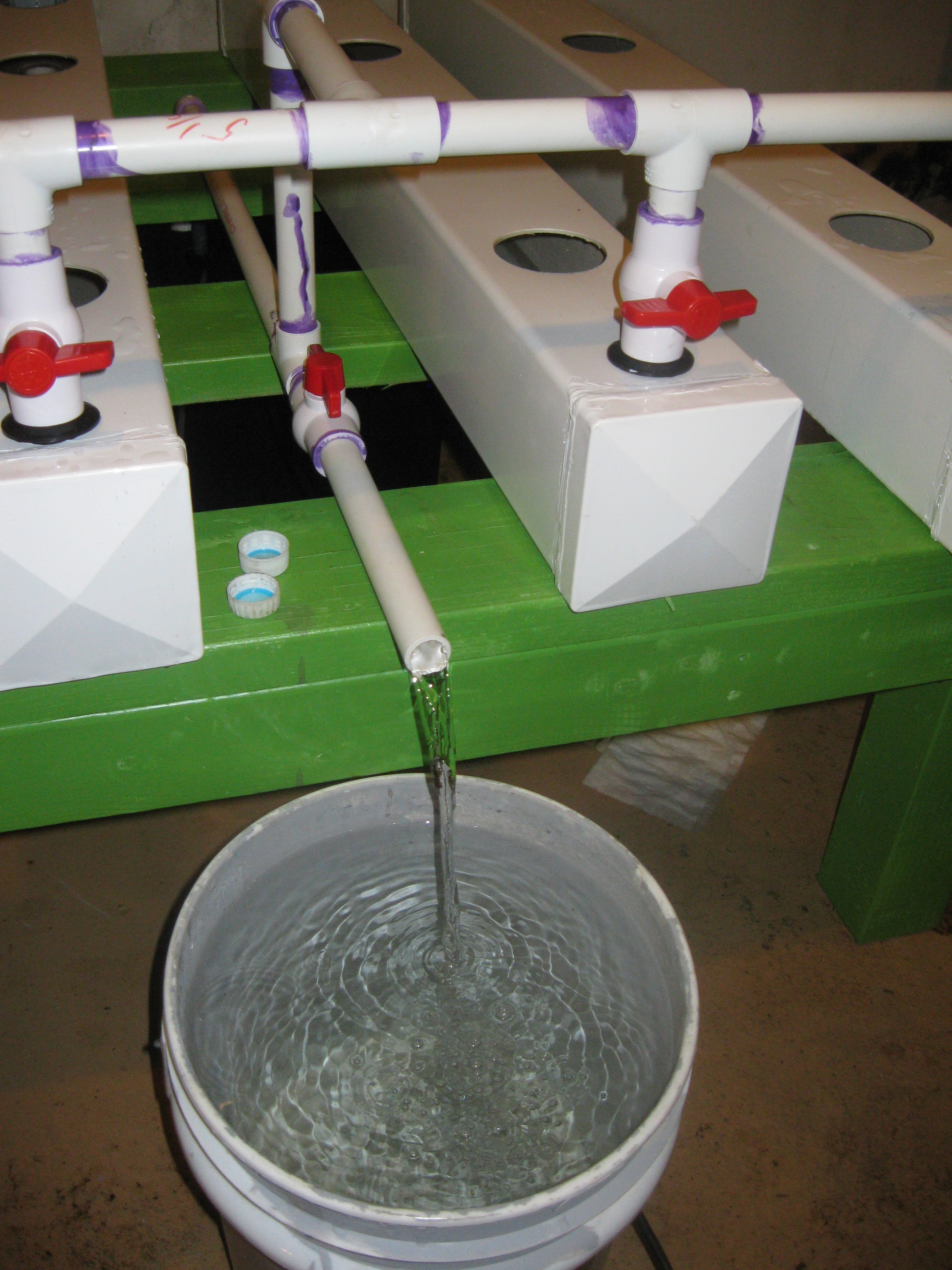
Additionally I wanted to test the reservoir pump out valve. This vale in the middle of the system is for using the reservoir's internal submersible pump as sort of a sump pump to drain out the reservoir into a bucket. The reason for this feature is for changing out water in the system if it get too dirty, the unit needs cleaning, etc for whatever reason you'd want to remove the water really. The whole idea is to make it easy and semi automated by using the same pump inside the reservoir and turning some valves. In order to use it the pump must be turned off, next the valves on each row need to be completely closed, finally the drain valve can be opened. The pump gets turned back on and pumps until the reservoir is empty.
![]()
Back to the topic of the pump being undersized. The mistake made with the pump choice comes down to a few things. Submersible pumps are rated in a height they can pump this is called the total dynamic head, this rating pertains to the vertical height the pump must move the fluid. The total dynamic head is also influenced by the design of the pipe fixture it is pumping into, in the case of the input manifold, also most total dynamic head ratings assume there is not fixture added. The trick is to design the pipe fixture or manifold in this case to fit within the range of the dynamic head of the pump. So basiclly I need to go back and take into account all the parameters of the manifold and make some calculations before getting a new pump. I plan on making a dedicated log explaining this a bit more clearly. Thats all for now, thanks for the continued support and stay tuned!
HydroPWNics
An open source hydroponic garden control, monitoring, and grow system with cloud database and dashboard.