AVR
AVR-
OMG It's an RF Project now
05/15/2015 at 05:53 • 0 commentsSo after thinking about the hardware as it stands(current revs/thoughts on teensy compatibility) I came to a conclusion: while its super nifty and easy to use a premade ESP8266 module, I'd like to further maximize the cost of the PCB so I'm going to integrate the ESP8266 chip, circuit, and antenna all into the Module Hub PCB.
I am still going to produce a prototype of the module hub as it is now as I need to test if the DCDC regulator's PCB layout allows for correct operation of the regulators (first time using these TPS chips). Once I confirm the layout on the DCDC regulators I will perform a redesign and integrate all the circuitry into one fantastically cost effective PCB. I've done 2.4GHZ RF before at a previous job so I know how to do PCB antennas and traces to minimize noise etc (can't comment much on the work because you guys know). This is going to be my first RF PCB on my own so I'm bound to screw it up but that's just the case with PCBs in general in my field its usually 3 times a charm, but then again every PCB is always work in progress, you can always doing it better and better. Anyways this means I will be sticking with the current hardware choices and not including Teensy compatibility as much as I like the idea, I don't feel like making another microntroller footprint (my least favorite part of the process, so much typing), and I'd like to challenge myself further with the addition of RF. Stay tuned for more PCBs and HydroPWNics!
-
Teensy Compatiblity? Maybe
05/13/2015 at 19:45 • 0 commentsOne thing folks will notice very quickly is that HydroPWNics makes heavy use of FreeScale ARM Cortex M0+ microcontrollers. I chose these MCUs for their very nice cost to performance ratio and low power capabilities. I am currently using two different MCUs the MKL05Z16VFK4 and the MKV10Z16VFM7. The ML05 is being used for modules because I want them to be low power capable and the L series (Kinetis L) designed for that. The MKV10 is on the hub and I intend that to be doing a bit more processing (sample modules, aggregating the data, rudimentary processing etc), hence the hire clockspeed. I also wanted to support both wired and wirelss functions so I needed the dual UART of the MKV10. Even thought the V series (Kinetis V) is targeted towards motion control and higher performance its still considered a low power product. Now that being said what if these modules had Teensy compatibility? The benefit of Teensy compatibility would mean that my modules could be compatible with the Arduino IDE and all of Paul's great libraries. It would effectively make this project Arduino compatible, which is handy to get other's involved in the project later on as it grows. Before I make a decision I should not this is not a simple switch either way. Teensy compatibility could be implemented by either porting the code base or swapping chips. This would mean redesigning all the modules around the Teensy chips or a project in itself for software.
Now redesigning the PCBs seems like a lot but to be honest they are not too compex, they are two layer designs using circuits I've played with before and took very little time to implement. What I need to do now, is perform some testing. Luckily I can get the MKL05 as a FreeScale Freedom board, so I can use that to test the sensors I plan to use and runs some benchmarks. The MKV10 doesn't have a Freedom board yet, there is talk of one but I haven't seen anything as of late. Next off I would have to evaluate Teensy. The Teensy LC is the most attractive one because its low cost and low power, despite all the custom hardware I am trying to keep costs down (see log about board cost estimates and look for the BOM post coming soon). The Teensy LC has a Cortex M0+ similar to the MKL05 but is equipped with USB, also the LC uses a QFN package which I like very much for the size and I find them very easy to solder. Despite the differences between the Teensy LC and my chips, I think I could make it work either way but first I want to do some testing. Stay tuned for more to come!
-
Supplies, Sensors, and Fence Posts (Wait What?)
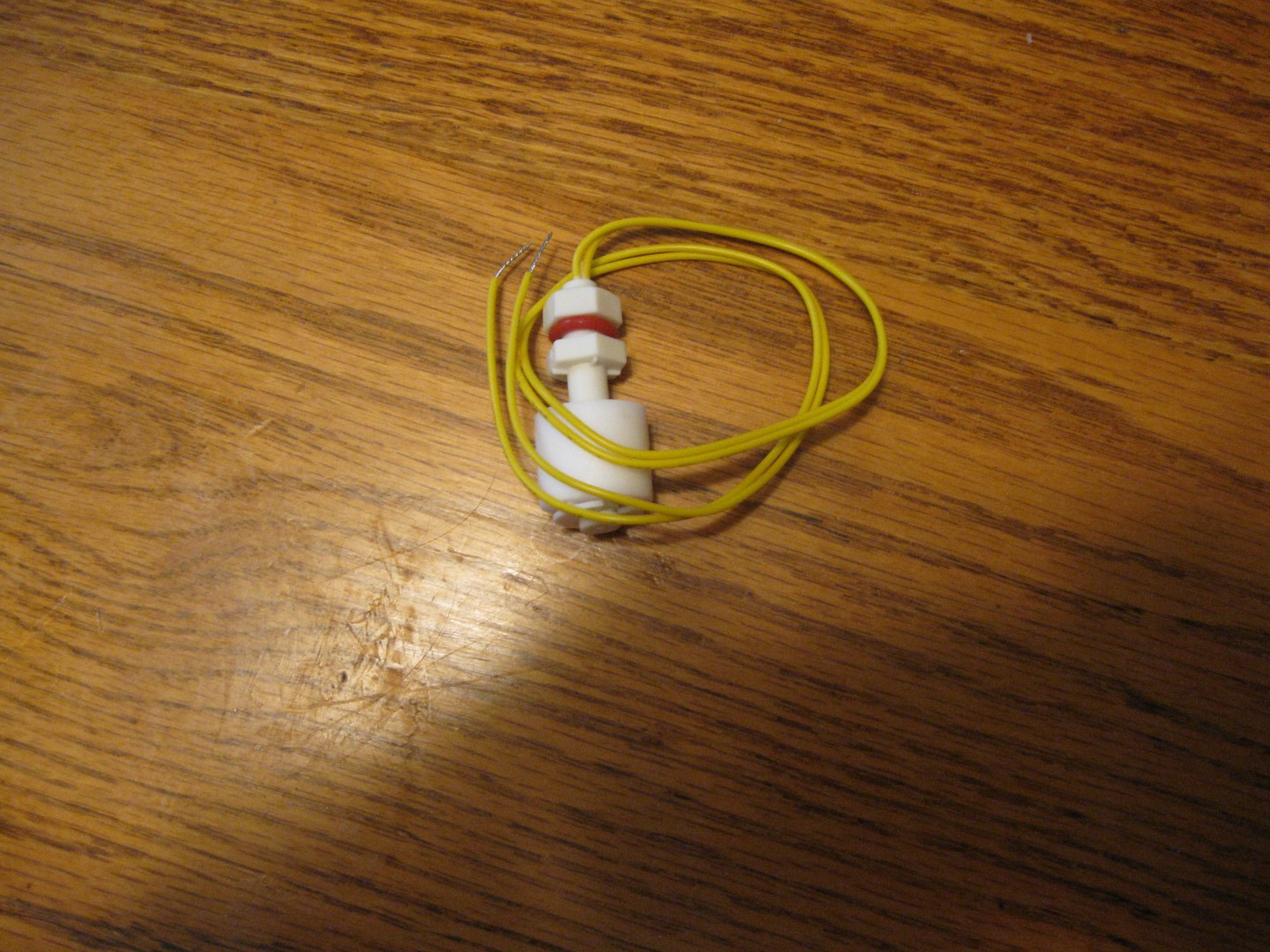
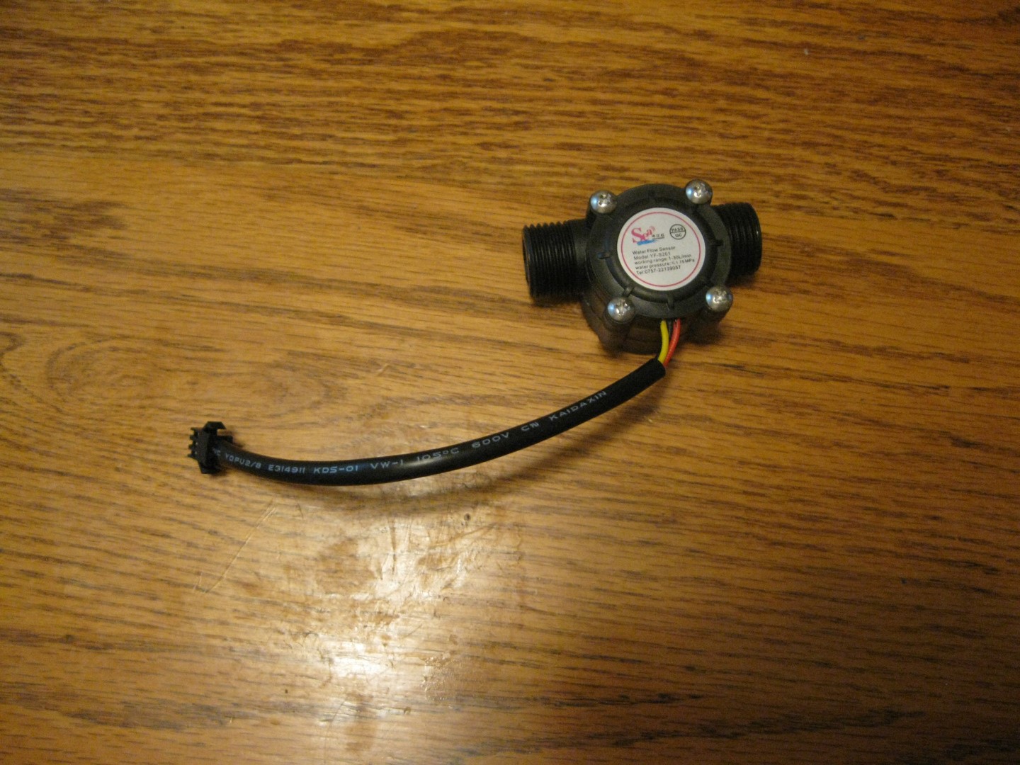
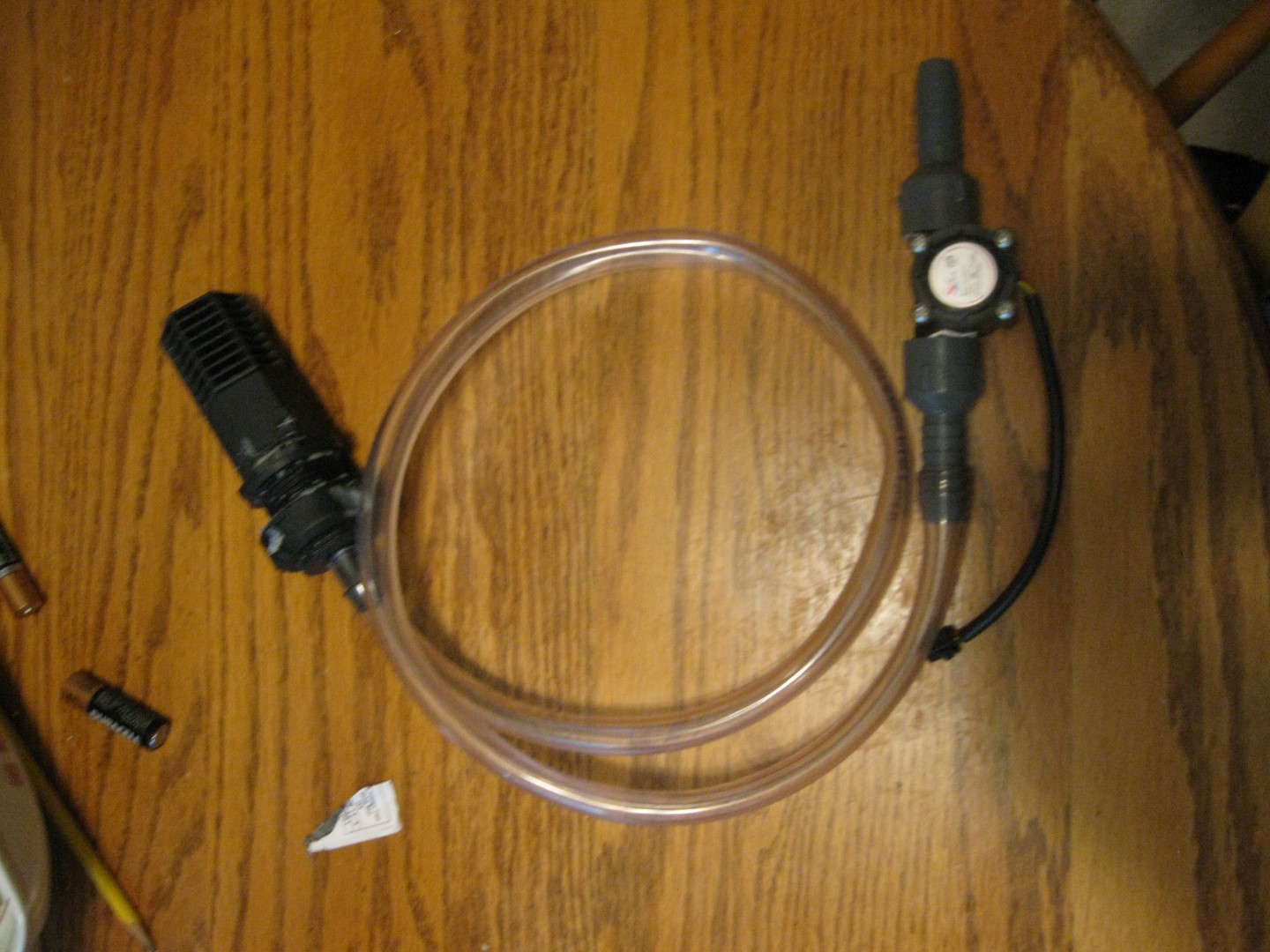
05/13/2015 at 19:01 • 0 commentsOver the the past weekend a few sensors and things came in the mail. Yesterday I went to the hardware store to pickup a few items for these parts. What came in over the weekend were, water level sensors, and flow rate sensors. The water level sensors are very simple (and cheap ;) ) they have floats on them and when those floats are moved by the water level they trigger a switch. Th idea will be to mount the level sensors in each grow unit, I will be using them to stop the pump on its initial startup, this will prevent overflowing while the pumps control cycle begins. The flow rate sensors are of the hall effect variety and feature 1/2 inch threaded fittings on each side. In order to get these sensors interfacing with the water pump, I needed some female thread to bard adapters, so that I can connect the senor inline with the water pump tubing. I should note that I purchased two of these sensors, so I can monitor the flow rate going in and the flow rate going out of the drain valve. The idea is that these sensors will be monitored by the pump control module, implementing closed loop control (PID) of the water pumping cycles. The goal is to keep the water circulating while keeping the water levels constant.
Water level sensor, the larger cylinder towards the bottom is the float that moves along the shaft triggering the switch.
![]()
Hall effect flow rate sensor, for monitoring flow in and flow out rates
![]()
Input flow sensor hooked up to ebb/flow input valve with the fittings discusses above
![]()
While at the hardware store (Lowes in case anyone is wondering) I discovered that the vinyl gutter that I wanted to use for my hydroponic grow units were too short and would not be deep enough for the basket pots I have on hand. I looked around the store to find PVC pipe bigger than the gutters I wanted to use but to no avail, the biggest PVC pipe they had was 4inch diameter and was for sewage. My initial backup plan if the gutters were too small was going to be 6inch PVC pip with endcaps, holes for the plants, and holes on the bottom for valves and sensors. In the back of my mind I was considering a third option that I've seen all over the web: Enter PVC Fencepost. Lowes may not have had my PVC pipe but they had 10 foot 5X5 inch square PVC fence post with endcaps!!! I originally wanted to avoid this as a material choice because it was more expensive than gutters, but to my surprise not too bad, the single post cost me 25 bucks and I will be making two units from it. I might make two more now that I know I can get this fencepost for a decent price in my home town. In the end this material switch was a good thing, its going to be a lot easier to drill holes for the pots since the surface is flat, I won't have to cover the top since is all enclosed around, and it the square profile allows for more root room. Next off I need to decide how to cut and drill out the post, so stay tuned, I should be doing more building than circuit design in the coming weeks!!!!
5X5 PVC fence post for making the two hydroponic grow units:
![]()
-
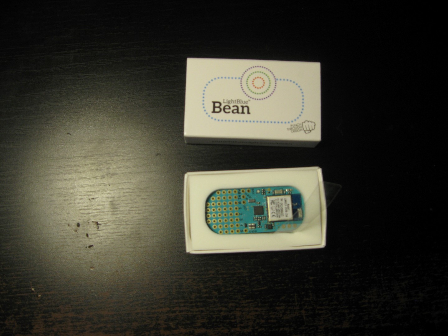
LightBlue Bean Impressions
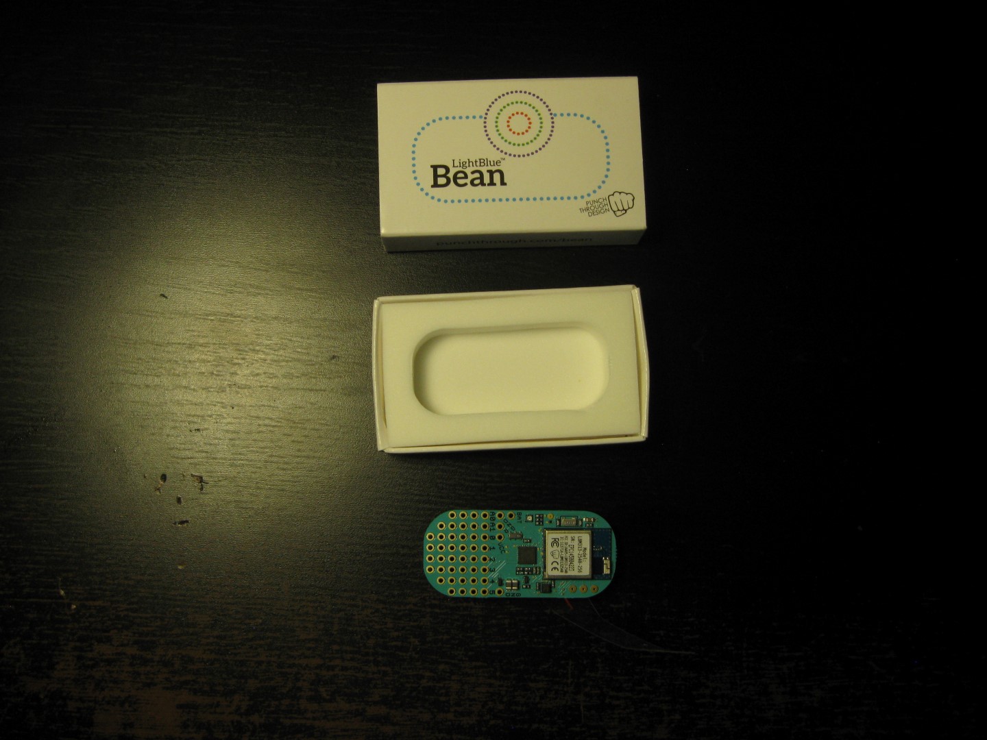
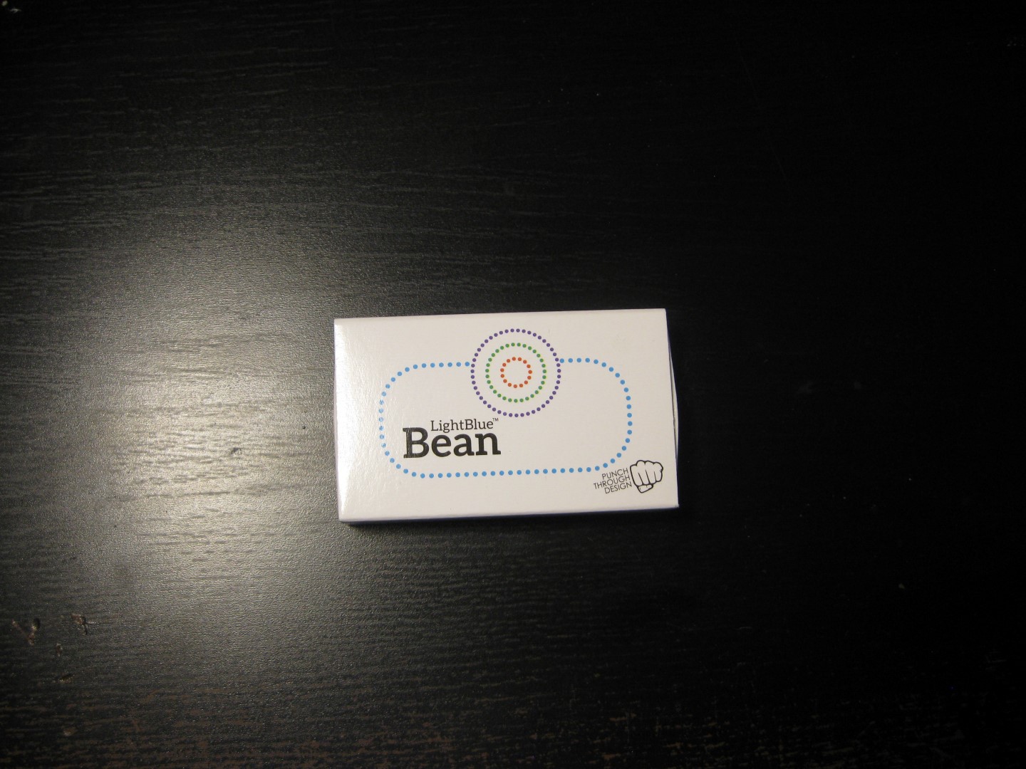
05/13/2015 at 18:00 • 0 commentsSo on Monday my LightBlue Bean prize came in (thanks again Hackaday!!!!!). When I got it I took some unboxing photos for you all, so check em out:
![]()
Open Box
![]() Out of Box
Out of Box![]()
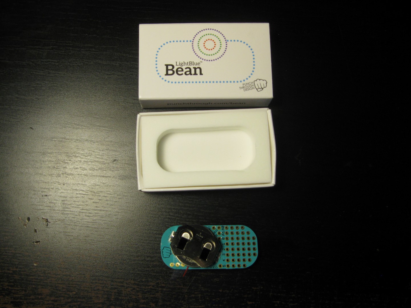
Out of Box Bottom
![]()
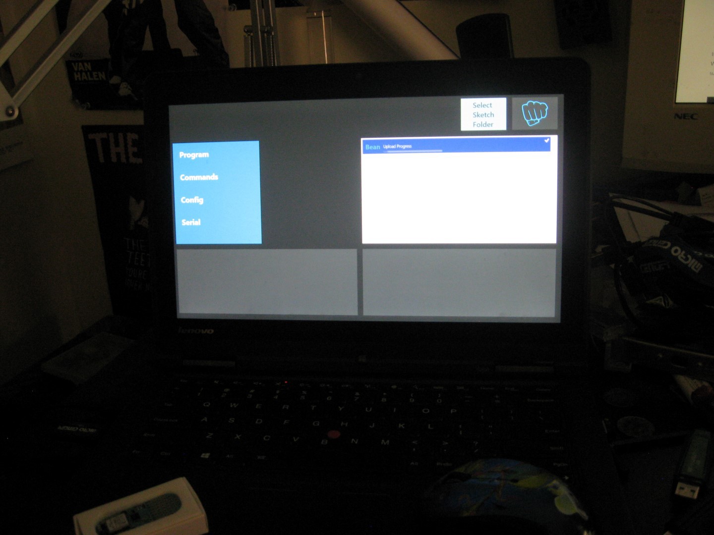
Windows 8.1 App
![]()
So overall the Bean is a pretty neat piece of hardware ans I must say fairly well laid out (tiny PCBs can be tough). The compactness is very impressive but I have to say the low power and battery life take the cake as far as cool factor. If your applications are developed such that you sleep peripherals and turn off things you don't need, you can get up to a year of batter life with the Bean, that's pretty impressive out of the box. Also can purchase the BLE module separately from Punchtrhough as well as a comprehensive dev board. The ability to use their awesome low power module is a nice plus especially because its FCC certified. I think my focus next time I play with the Bean will be exploring the BLE module more, I'd like to use it on some of my own designs.
The software for the Bean is interesting to setup. When I got the bean I setup my laptop with all the appropriate software, one thing Windows users should know is that WIndows support is still relatively new. Since my mac died in December I've been rocking Windows and Linux PCs in its place, it seems the Bean is best supported on OSX and iOS, if you are on a Mac you might have a better time than I am. Anyways in order to use the Bean with windows you need their Windows 8 app (Windows App Store), the Arduino IDE, and their patch to allow the IDE to compile code for their board. The App is handy (especially for me with a transformable tablet laptop Thinkpad Yoga S1 in case anyone's wondering) it allows you to test out functions, read the sensors, and blink and LED all from pressing buttons on the app. I should also note that pairing the device is pretty easy, just open the Settings app on Windows 8 and pair it in the add devices menu. The only issue I ran into was the app was failing when attempting load a compile project to the Bean, and I cannot figure out why as of yet. If anyone else is using the Bean with Windows 8 I would love to know how to get it to program (hopefully its something I'm overlooking), so feel free to comment! Another thing I should note is that it seems that there isn't much support for Linux that I know (official support) which is bothersome as Linux is my OS of choice for embedded software development, hopefully Linux will get native support in the meantime, users can solder pins on and hook up ISP programmers (might go this route on windows too), I might do this myself just to keep all my dev environments in the same place.
As for using the Bean in HydroPWNics I didn't have very many ideas at first since I had planed on using the ESP8266 ESP-12E module, but then I had an idea. My idea is to make a standalone weather station for deploying HydroPWNics systems outdoors. The idea came to me upon seeing rechargeable solar powered garden lights. My first thought was "that is a dedicated low power solar power/storage center and a waterproof enclosure". These lights are cheap (between 5-20 bucks each) and would make for a great starting point. The reason why I'd want to do this with the Bean is that it is low energy and I can place it almost anywhere and have it provide data to the garden. The ability to place it almost anywhere will allow me to place it in a location where it can get accurate sensor readings, instead of forcing it to be close to the garden. The Bean also has a temperature sensor, and if I create some sort of moving mounting system I could use the accelerometer to monitor wind! At the moment the wireless weather station isn't the highest priority but later down the road I will explore it more fully. Thanks again for reading and thanks to Hackaday for the awesome Prize. Stay Tuned!!!!!!!!!!!!!!!!!!!!!!!!!
-
PCB Fabrication Estimates
05/12/2015 at 03:27 • 0 commentsLate last night (and early this morning ;) ) I decided that I wanted to do more and I did some estimates on PCB costs. First I generated fabrication output files for my board, I created gerber files and NC drill files, and second used OSHPark to get cost estimates. While creating the fabrication files I noticed that I forgot to tent my vias, remember if you are doing a SMD board and you have components close remember to tent vias with solder mask to prevent solder bridged shorts. I haven't yet decided which board house I'm going to use yet, but I'm leaning towards OSHPark. Normally OSHPark is my go to for all prototypes but I have a huge backlog of 2 layer PCB projects and I'm contemplating getting them all done on the same panel, probably from 4PCB or another volume boardhouse.
Anyways I will start things off with the sensor modules. If you noticed earlier both of the modules are the same size so they have roughly the same cost. From OSHPark both the digital and analog sensor modules will cost $16.60 for 3 boards. This is not bad at all and I'm sort of pleased that I made it under 20 bucks. It is my hope that the boards components will also be a similar cost but we will have to see BOM is next. And now for pictures:
Analog Sensor Module OSHPark Rendering Top
![]()
And Bottom
![]()
Digital Sensor Module Rendering Top
![]()
And Bottom
![]()
Lastly the module hub. The module hub is bit bigger and therefore a bit more pricey than the sensor modules. The higher cost of the module hub is ok, there will only one hub per plant grow unit (each unit has 4-6 plants). Now the original hub I designed was cheaper but it wasn't wireless, that version was going to require an additional piece of hardware to communicate with all of the hubs. Instead of designing another piece of hardware that would have acted as a pass through and wifi module I decided to compromise and make the hub wireless but only support 3 modules. At first I wanted to just add wifi but that ended being a bit too expensive so I decided to shrink it down and give up a module. Anyways the module hub came to approximately $25.90 for 3 boards, which is not too bad, I'm hoping to hit a total cost of under 50 dollars for an assembled hub.
OSHPark Render of the Module Hub Top
![]()
Module Hub OSHPark render Bottom
![]()
So thats that for PCB estimates, there will be another post when I decide which house to use. Stay tuned for updates realting to the BOM and much much more!
-
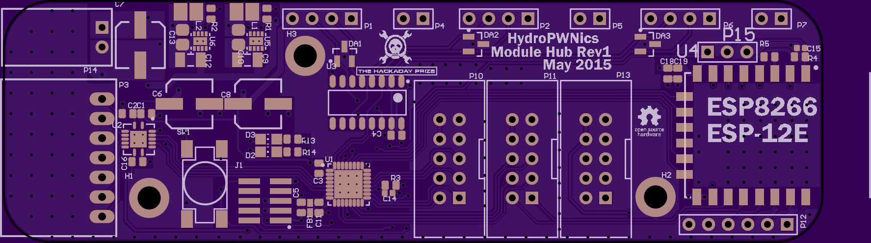
Update: The addition of WiFi and More
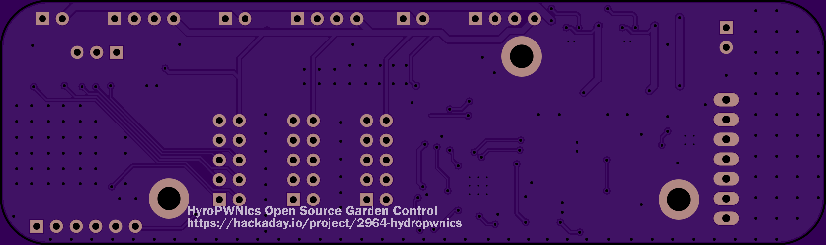
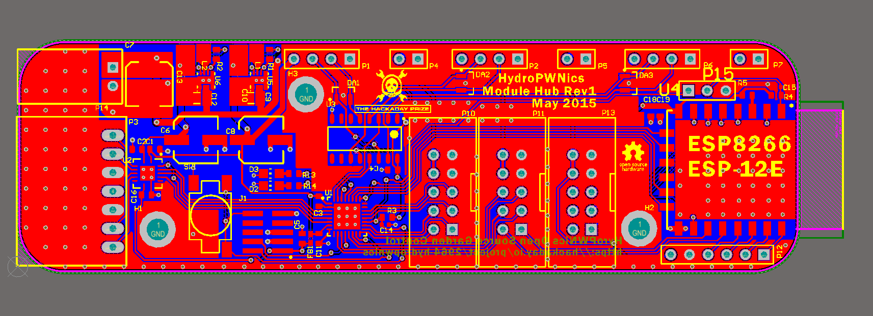
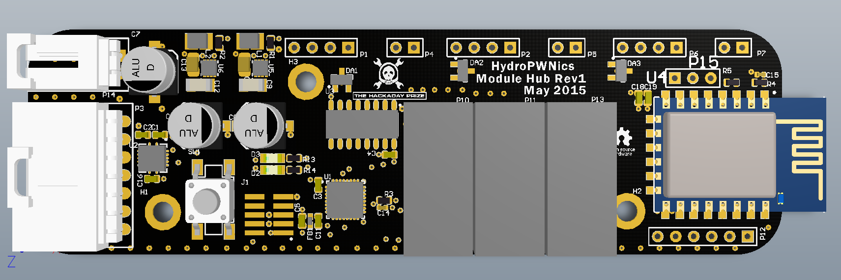
05/11/2015 at 03:19 • 0 commentsLets see where do I start. So today there is a pretty big update to the three piece of hardware that I have been working/talking about related to HydroPWNics. The first big update was to the Module Hub, I reworked it to support only 3 modules BUT now it sports a ESP8266 ESP-12E WiFi module and a smaller size (cheaper PCB yay). IN addition to the smaller size and WiFi, the board has my resized M3 screw holes and 1/4 radius rounded corners. The MKV10 ARM will talk to the ESP-12E module over SPI, streaming the latest readings off the modules to the cloud. Also one lat thing that was added were neat Hackaday Prize logos :) . The New Module Hub:
![]()
3D Rendering of WiFi Enable Module Hub:
![]()
Module Hub WiFi Spec:
- MKV10Z16VFM7 - 32 Pin QFN 5X5
- 3 Module Ports with 12VDC Power
- ESP8266 ESP-12E WiFi Module
- On Board DCDC 3V3 regulator for 1A 3V3 DC Power
- On Board DCDC 5VDC regulator for 1A 5V DC power (level shifter/expansion)
- ARM Cortex M JTAG Debug Connector
- 74HC4052 Analog Multiplexer Demultiplexer for UART module Interfacing
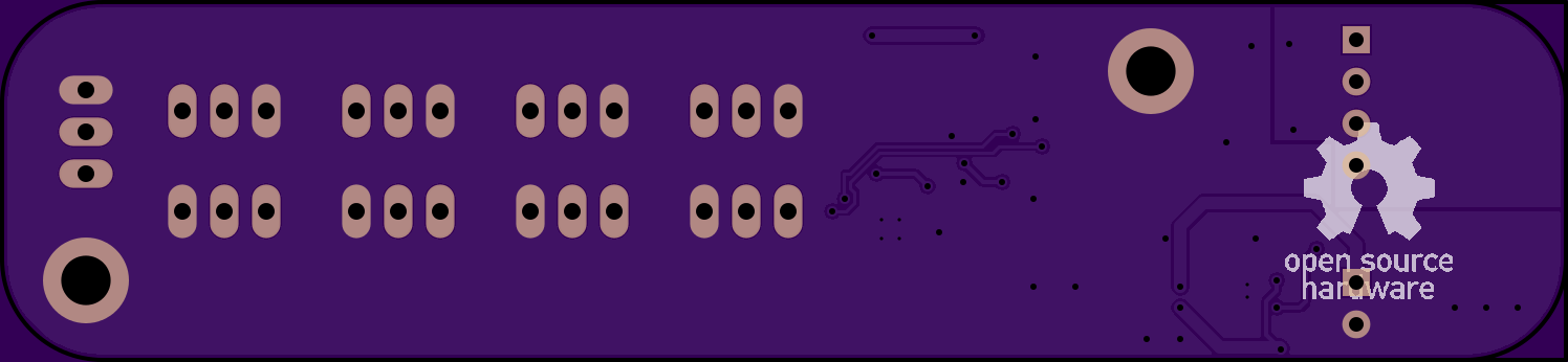
- 4 M3 Screw Mounting holes
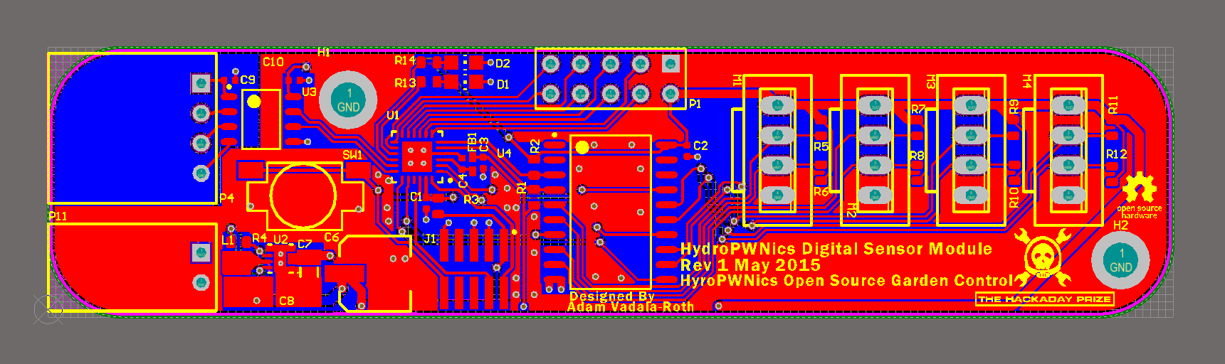
Next on we have the updated sensor modules. Not much has changed with the sensor modules since I posted their revised versions a few days ago. The major change to both modules is the addition of 1/4 inch radius rounded corners (to make all the boards "match") and the subsequent remodeling of the topology to fit everything on the modified shape. Additionally open hardware and hackaday prize logos were added to the modules. With out further due the new modules:
New Digital Sensor Module
![]()
New Digital Sensor Module 3D render:
![]()
Specs
- MKL05Z16VFK4 ARM Cortex M0+ 48MHZ MCU
- 4 I2C Sensor Inputs with 3V3 DC Power
- On Board DCDC 3V3 regulator for 1A 3V3 DC Power
- ARM Cortex M JTAG Debug Connector
- 8 GPIO pins, power, ground Expansion connector (SPI signals included, some ADC too)
- Galvanic isolation
- M3 mounting holes
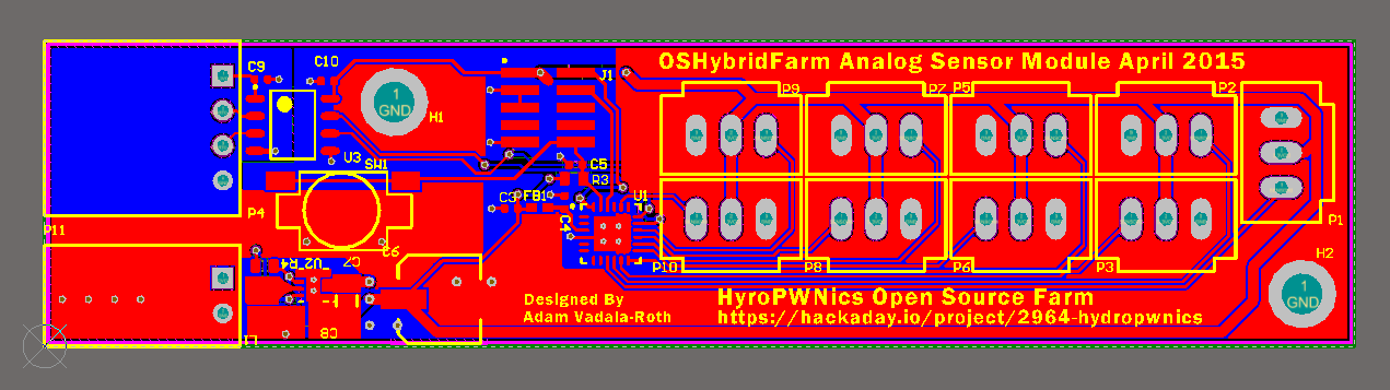
New Analog Sensor Module:
![]()
New Analog Sensor Module 3D Rendering:
![]()
Specs:
- MKL05Z16VFK4 ARM Cortex M0+ 48MHZ MCU
- 9 Analog Sensor Inputs with 3V3 DC Power
- On Board DCDC 3V3 regulator for 1A 3V3 DC Power
- ARM Cortex M JTAG Debug Connector
- Galvanic isolation
- M3 mounting holes
So far the hardware of the project has been moving very quickly, the next step will be making comprehensive BOMs for each of the boards then off to the fab, thinking OSHPark but might try something new. When the current set of modules are ready for fab I will be moving on to the closed loop control board since it will be used in quite a few places on the project. Stay tuned for more hardware and updates!
-
Blue Bean Prize
05/08/2015 at 15:01 • 0 commentsThe latest update to the HydroPWNics project is that, it won a LightBlue Bean from the weekly giveaway! I'd like to say thanks to Hacakaday for the awesome prize, it feels wonderful to have had my project get noticed and be awarded! When it arrives I will do another log post unboxing it and giving my overall impression of it. How I will used the Blue Bean in the HydroPWNics project has yet to be determined, I'm thinking it will serve well as a handy wireless development tool during the development of the project and then maybe as a remote control, if RPi support is added to the Blue Bean. Anyways thanks again hackaday, I'll use it well!!
Article:
http://hackaday.com/2015/05/07/were-giving-out-125-teensy-lc-boards-this-week/
-
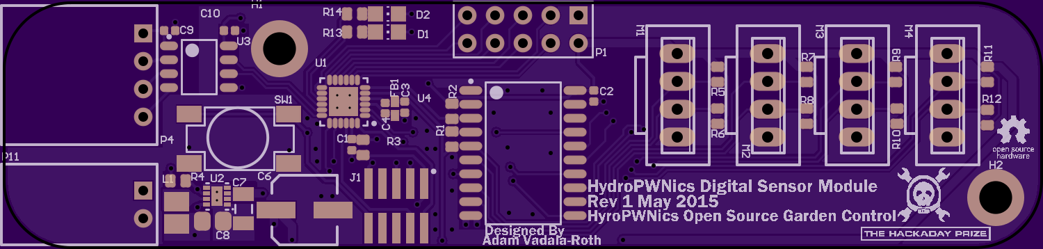
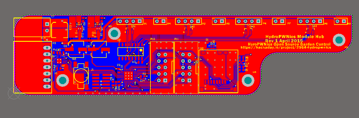
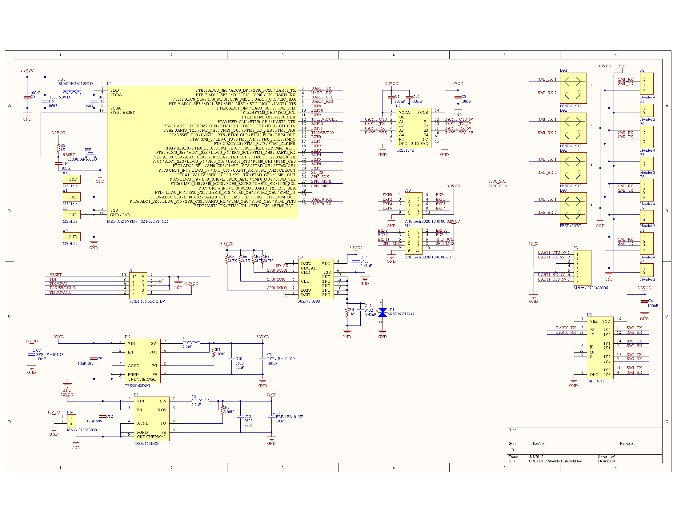
Module Hub and New Modules
05/06/2015 at 03:23 • 1 commentOver the weekend I worked out the hardware details for interfacing and networking the sensor modules with the DyIO. I developed a new board, it's called the module hub because it is just that a hub for modules. It has 4 ports for connecting up to 4 sensor modules, a FreeScale ARM CM0+ MKV10Z16VFM7 75MHZ MCU, analog multiplexer for UART, two expansion IO ports, a full handshake UART serial port, and power port. At first the the design of this hub was to be a simple 74 logic based board that would allow the DyIO to multiplex its UART port's signals to interface the four modules, this idea was abandoned in favor of an implementation that can interface with the DyIO via its serial port. Interfacing with the serial port on the DyIO required a full UART peripheral also another UART would be needed for interfacing with the modules, this is the reasoning behind using the MKV10Z16VFM7 MCU for the hub. The MKV10Z16VFM7 was chosen for its cost, rich and diverse array peripherals, and its 75MHZ clock. The way this board works is the MKV10Z16VFM7 communicates with the DyIO on one UART port and on the other UART port interfaces with the sensor modules using an analog multiplexer/demultiplexer IC . Another benefit to implementing the interface this way is that it may not require any modification to the DyIO firmware, everything should be able to be handled via the firmware on the modules and the Java API. The hub's will be mounted in custom cases (3D printed) and bolted to the sides of each of the grow units. The hub cases will be slotted such that the modules can slide in. The idea behind the system is that each unit is customizable based on the kinds of sensors needed for the given plants in the grow unit. The next step will be interfacing multiple modules to a single DyIO. Without further do pictures of the Module Hub Board:
Module Hub Revision 1
![]()
3D Render
![]()
Schematic
![]()
New Modules
As for new modules there are a few, water pump control, light control, and water quality. The water pump module will be simple, containing the MKL05 ARM CM0+ MCU, a PWM output for SS relay, sensor inputs for water level sensors, and inputs for flow sensor. The goal of the water module is for closed loop control of the water level in the hydro units. The light control module will simply turn lights on and off perhaps a light sensor to detect if the lights do go on. Water quality module is going to simplify quite a few things. IN a previous project log I bragged about wanting to implement full open source water quality monitoring but that's a project in its self. To make things easier I will be using the Atlas Scientific kit, probes and circuitry, the module will mount the PCBs, BNC connectors, and aggregate the data of the sensor boards. Water quality monitoring is the most expensive part of the electronics so I'm now 100% if I want to implement it from the get go, it will be the last thing to add.
Lastly there are two additional modules that I didn't mention before, it's because they are not of the variety that connect to the module hub. These modules are the nutrient distribution module and the air valve control module. These modules are going to be designed standalone and embedded into the devices they intend to control, they will have the same software interfacing as all the other modules and be controlled via the same API but from a hardware standpoint they are fully standalone.
Anyways stay tuned fro new modules and updates!
-
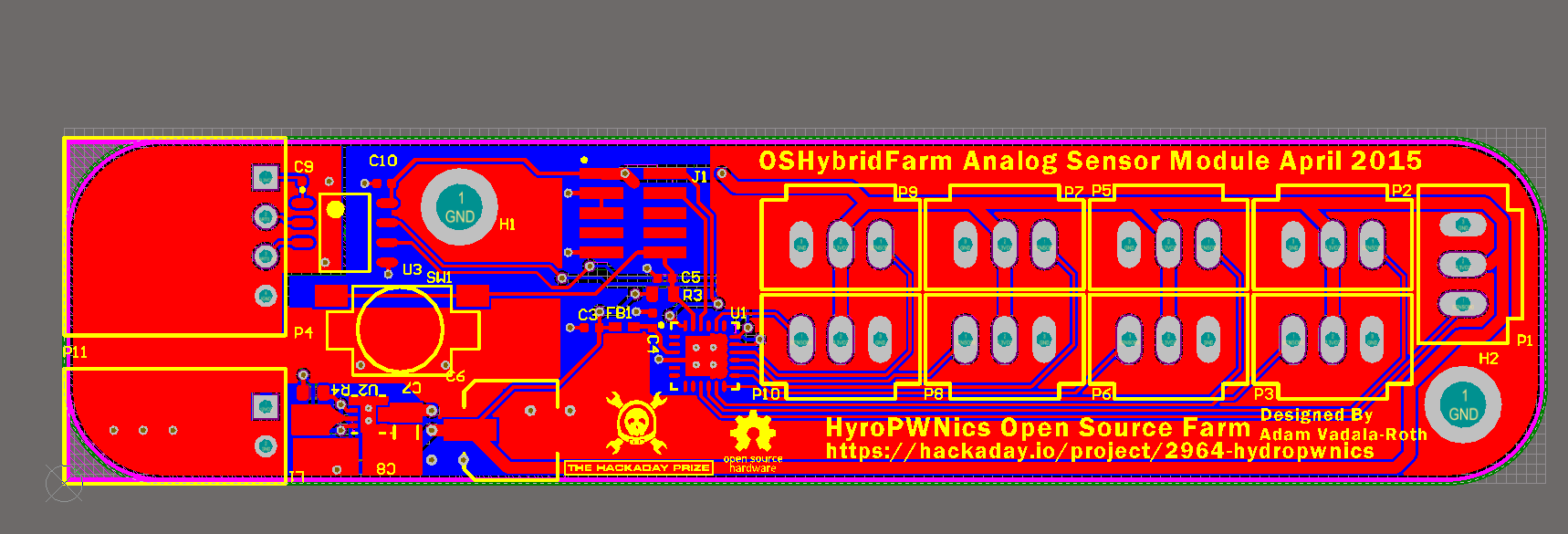
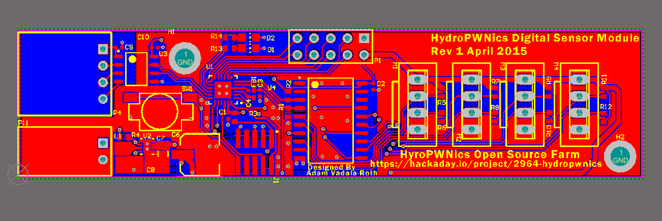
Sensor Modules Galore!!!!!!!!!!
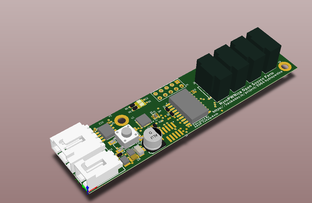
04/30/2015 at 06:16 • 0 commentsToday is sort of a big update. After many hours of working and researching I have finished the prototype designs for both the analog and digital sensor modules. Originally I was going to have one sensor module that did both analog and digital with the idea being I would fabricate a lot of these and just keep adding as many as I needed. I decided to go the more modular route and have a digital sensing board and an analog one. The main new addition this post is the digital sensor board as the analog one was only revised. The digital board is essentially an I2C multiplexing node designed to interface with 4 I2C sensors, provide them with power, and poll/aggregate the data for transmission to the DyIO via UART. The idea is to use a pair of these modules per grow unit and use I2C humidity and temperature sensors. Working on the digital sensing board brought in many new features that are now on both the analog and digital sensor modules and will be standard with all future modules. The features introduced were a standard form factor with mounting holes (M3), separate power connector for 12VDC (Molex clip), Galvanic isolation of the UART signals on the MKL05 ARM CM0+, and a separate connector for UART serial (Molex clip). Without further do the digital sensor module :
Digital Sensor Module Rev 1
![]()
Digital Sensor Module Rev 1 3D Render
![]()
Digital Sensor Module Specs:
- MKL05Z16VFK4 ARM Cortex M0+ 48MHZ MCU
- 4 I2C Sensor Inputs with 3V3 DC Power
- On Board DCDC 3V3 regulator for 1A 3V3 DC Power
- ARM Cortex M JTAG Debug Connector
- 8 GPIO pins, power, ground Expansion connector (SPI signals included, some ADC too)
- Galvanic isolation
- M3 mounting holes
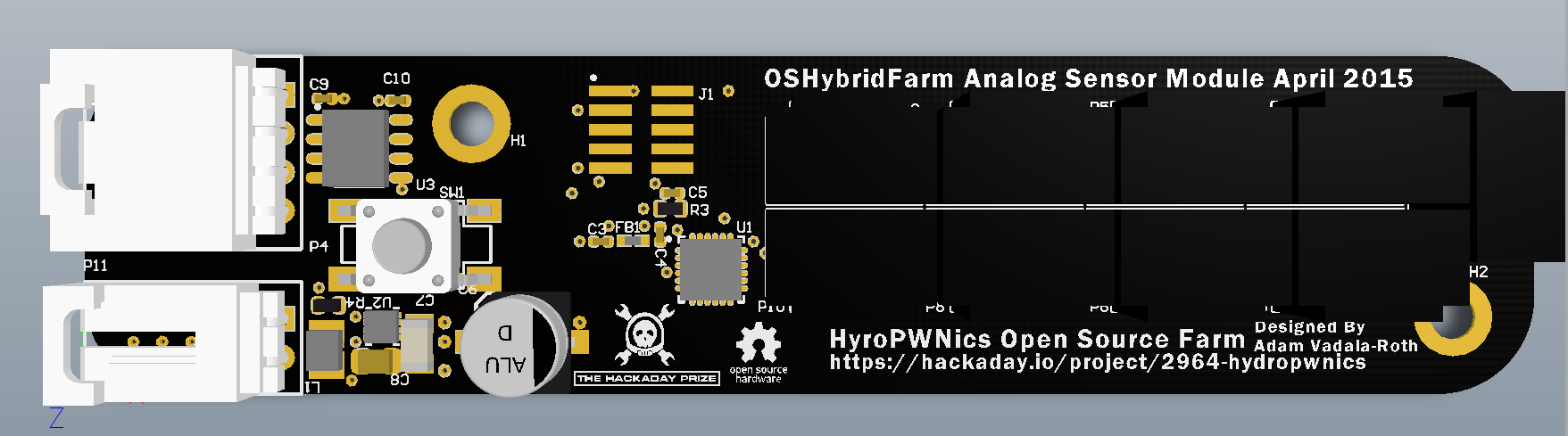
Updated Analog Sensor Module featuring same new standard features as the digital module:
![]()
Specs:
- MKL05Z16VFK4 ARM Cortex M0+ 48MHZ MCU (QFN 24 Pin)
- 9 Analog Sensor Inputs with 3V3 DC Power
- On Board DCDC 3V3 regulator for 1A 3V3 DC Power
- ARM Cortex M JTAG Debug Connector
- Galvanic isolation
- M3 mounting holes
3D Render of new Analog Sensor Module
![]()
With these two modules designed I'm ready to start fabricating prototypes, I will probably get them done via OSHPark so I have a few of each to play with. Stay tuned for more updates, the next big board will be the UART multiplexer power dispatch module! Source and schematics (PDF) found at the following Github Repository:
-
Updates and The Addition of Water Quality Monitoring
04/28/2015 at 00:52 • 0 commentsHey folks, not sure how many people are looking at this page as of yet but for those who do I feel I should explain what's going on with the project a bit more. So as you all may know this project is pretty big, initially it was going to be a software project relegating all hardware interfacing to the DyIO module but I'm hardware engineer and just couldn't resist making more PCBs. That really explains why my logs thus far have been randomly the PCB stuffs and not anything else, I'm just working on what I'm most interested in at the moment and the rest will come after. Now to clear things up, in this post I'm going to give a more detailed breakdown of both the hardware and the software, (the project is still young and developing so a lot of this is subject to change bear with me).
The initial idea was a simple hydroponic garden with internet connectivity, controlled water pump cycles, and controlled lights. Originally it was going to be a DyIO module and a couple relays in a PVC wiring box with plug outlet on the side for the lights and the water pump with an old laptop running the java app. Initially just a simple java software project with minimal hardware, but I have since decided to make it a more comprehensive system with full autonomous. The new system builds on the original concept of the described PVC wiring but adds serial ports on the side to interface with external hardware. Enter the Senor modules, one for analog sensors, digital sensors, and the new addition water quality sensing. The analog and digital sensor modules handle very simple sensors, e.g ones that can be read by an ADC or I2C (digital sensor board is I2C/1W), they will be performing most of the monitoring of the plants. Water quality sensing will be its own module because it requires lots of custom circuitry and will not follow the general purpose design of the other modules. Initially water quality sensing will be very basic, I'm going to start with pH reading of the nutrient solution as well as temp. The plan eventually will be to monitor all the characteristics of the water, dissolved oxygen and electrical conductivity. I should note that water quality monitoring will be specifiy to the hydroponic part of the hybrid farm, but the other sensor modules will be used on both parts. That's the initial plan for the hardware, it's going to be a lot of PCBs (hopefully not too many revisions per module) but it will simplify the wiring of the control box and keep the java application very simple and light.
For software to control the system described above, the main application will consist of a Java web app interfacing with the control box via the USB on the DyIO. The DyIO is basically the central hub/master controller talking to all the boards and modules via serial, this keeps the Java app clean and simple putting almost all the control and sensing tasks into the microcontrollers on the modules.
HydroPWNics
An open source hydroponic garden control, monitoring, and grow system with cloud database and dashboard.
 Out of Box