Teensy Audio Library
CD quality sound processing, integrated with Arduino sketches
CD quality sound processing, integrated with Arduino sketches
To make the experience fit your profile, pick a username and tell us what interests you.
We found and based on your interests.
I've created a new version of the CS42448 TDM test board. It's updated for Teensy 4.x pinout.
An unpleasant discovery from the prior version was how hot the CS42448 chip runs. On this 2nd version, I've added copper underneath the chip and on the bottom layer to try to dissipate some of the heat.
I also added a PCM1808 ADC, so all 8 inputs can be used instead of only 6.
This version also adds a 14 pin header in the center, so it can be easily connected to the Dual Interleaved CS42448 board... which is still a work-in-progress.
https://hackaday.io/project/176368-dual-interleaved-cs42448-chip
My hope is to eventually be able to connect 2 of these boards to each TDM port, so all 16 inputs and all 16 outputs can be used. With 2 TDM ports, that should make 32 simultaneous audio input & output possible.....
Some projects need a lot of audio I/O. Maybe you’re doing positional audio sound effects (using the 8-tap delay effect) where ordinary stereo or even 5 channel “surround” isn’t enough? Maybe you’re making the ultimate Eurorack synthesizer module? Or you just want a lot of signals, because you can!
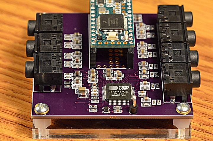
Here’s a board for the Cirrus Logic CS42448 chip, which provides 6 inputs and 8 outputs. All are high quality audio, and all work simultaneously.
Normally digital audio is communicated between chips using I2S protocol (which is different than I2C, despite the similar acronym). Two I2S streams can be used for quad channel, but to really step up to more channels, you need TDM protocol.
TDM, which stands for Time Division Multiplexing, communicates a frame of 256 data bits. For 44.1 kHz, this means the bit clock must be 11.3 MHz. Only 4 signals are used, one to transmit all 256 bits and another to receive all 256, a frame sync signal the marks where each 256 bit frame begins, and of course the 11.3 MHz clock.
Here is the TDM waveform documented by Cirrus Logic for the CS42448 chip.

When viewed on an oscilloscope, here is how the TDM signal actually appears:
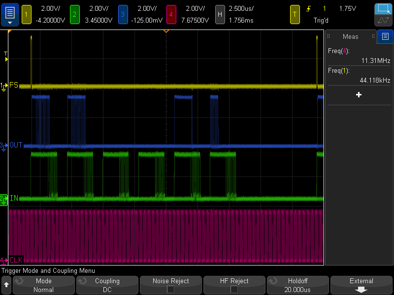
During this test, the code below was running. The output from Teensy is the blue trace. It sends a 16 bit guitar synthesis to CS42448 AOUT1 & AOUT2. Because the CS42448 outputs are 32 bits, but the audio is only 16 bits you can see the lower 16 bits are always zero. Most of the rest of the output is zeros, except this example also brings in AIN1 and sends its top 16 bits to AOUT5 and its lower 16 bits to AOUT6.
Of course, the green trace is the data being received from the CS42448. All 6 inputs were left unconnected. Even through the channel slots of 32 bits, the CS42448 only produces 24 bits of data, and its lower 8-9 bits are mostly random noise. This PCB uses only the simplest single-ended input circuit. The better opamp-based differential circuit documented in the CS42448 could be expected to improve performance.
TDM support has recently been added to the Teensy Audio Library. It’s accessed by creating AudioInputTDM and AudioOutputTDM objects.
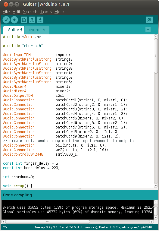
Each AudioInputTDM creates 16 simultaneous inputs. Like all communication in the Teensy Audio Library, the data is 16 bits wide. 16 of these channels gives access to all 256 incoming TDM bits. For CS42448, only channels 0, 2, 4, 6, 8 & 10 would be really useful.
Likewise, each AudioOutputTDM object can accept 16 simultaneous 16 bit audio streams, to fully control all 256 bits of the TDM output frame. For CS42448, only the 8 even numbered channels are useful.
You might think sustained 11.3 Mbit/sec communication would be difficult on a microcontroller, but it turns out Teensy's digital audio port with FIFO and its DMA engine make this quite easy and efficient. Yes, really!
Development of the audio software support is being discussed on this forum thread. If you make one of these boards, please join the conversation!
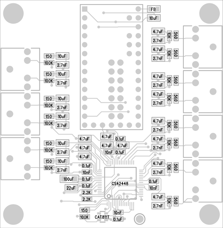
1   CS42448, Codec Chip            598-1033-ND
 1   CAT811T, Reset Chip            CAT811TTBI-GT3OSCT-ND
 7   Connector, audio               CP1-3525N-ND
 7   Resistor, 150 ohm, 603         311-150HRCT-ND
 8   Resistor, 560 ohm, 603         RMCF0603FT560RCT-ND
 2   Resistor, 2.2K ohm, 603        311-2.20KHRCT-ND
 8   Resistor, 10K ohm, 603         311-10.0KHRCT-ND
 7   Resistor, 100K ohm, 603        311-100KHRCT-ND
14   Capacitor, 2.7nF, NP0, 805     445-7508-1-ND
 4   Capacitor, 10nF, X7R, 603      490-1512-1-ND
 7   Capacitor, 0.1uF, X7R, 603     490-1524-1-ND
14   Capacitor, 4.7uF, X5R, 805     1276-6463-1-ND
 7   Capacitor, 10uF, X5R, 805      399-4925-1-ND
 1   Capacitor, 22uF, X5R, 805      490-1719-1-ND
 1   Capacitor, 100uF, X6T, 1206    490-10525-1-ND
 1   Inductor, Ferrite Bead, 805    490-1054-1-ND
 1   Circuit Board                  oshpark.com/shared_projects/2Yj6rFaW
 1   Teensy 3.2, 3.5 or 3.6         www.pjrc.com/store/teensy32.html
 2   Socket, 14x1                   www.pjrc.com/store/socket_14x1.html
 2   Header, 14x1                   www.pjrc.com/store/header_14x1.html
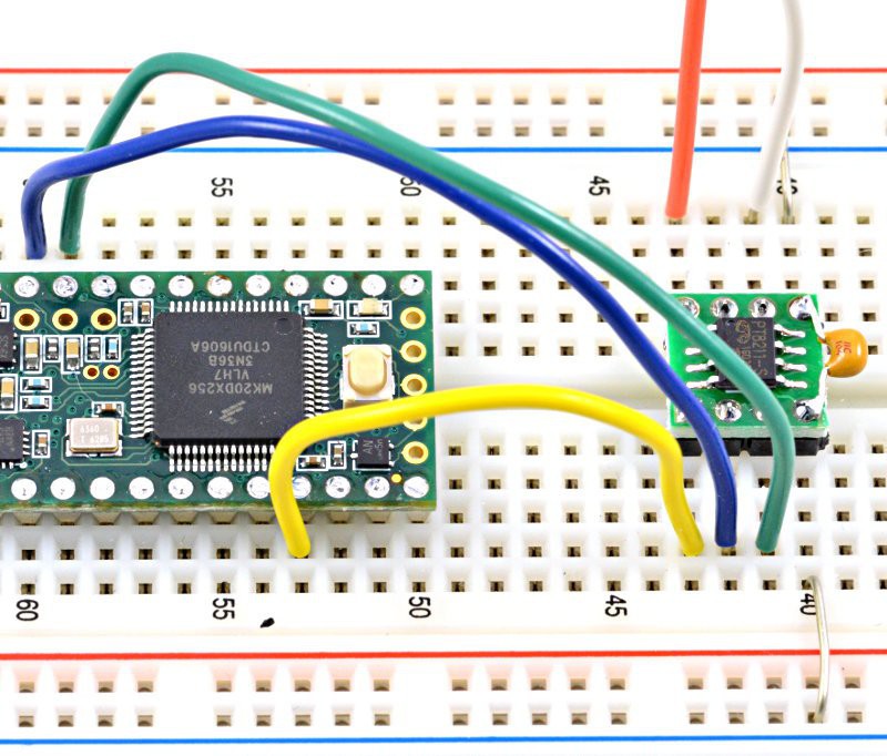
1 Heatsink (optional: CS42448...Thanks to a great contribution from Frank and Ben, the PT8211 DAC which sells for about 20 cents is now supported. They even put in 4X oversampling, so you get nice-looking waveforms at higher audio frequencies with only a simple analog low-pass filter.
USB audio connectivity has recently been added, based partly on earlier work by @Michele Perla
You can now place AudioInputUSB and AudioOutputUSB objects in your Arduino sketch and connect them to any of the other Teensy Audio Library stuff. Any sound send to a AudioOutputUSB object arrives on your PC/Mac as if you'd connected a line-in. Sound your PC plays (if the Teensy's audio is selected in your sound control panel) arrives at the AudioInputUSB object.
Currently this is all very new code, only on Github. Details are here:
https://forum.pjrc.com/threads/24309-USB-Audio-for-Teensy-3-0/page2
Within the next few weeks, a Teensyduino beta test installer will be published, to make trying this much simpler. But if you'd like to give this a try, of course you can download the stuff from github and copy to the correct location within your copy of Arduino, and edit boards.txt to make Audio appear in the Tools > USB Type menu.
At this very early stage, the design tool hasn't been updated with these new objects. You'll need to edit the audio objects right in your sketch. The simplest way involves using the I2S objects and then you just change from I2S to USB.
Today I added 4 channel I2S output support to the library.
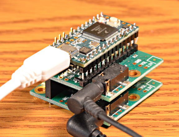
Teensy sends 4 audio channels simultaneously.
To use it, you need 2 audio shields... or 2 of anything else that takes I2S digital audio input. With the audio shields, a small hardware mod is needed on the 2nd shield, to route the 2nd stereo data stream to its input, and to configure for a different I2C address to you can control is separately from the 1st board.
Conversation about the development is on this forum thread. The design tool has been updated with "i2s_quad", so you can easily use it with whatever 4 audio channels you can design. The library has a simple example sketch that plays 2 WAV files to both outputs at the same time.
Maybe I ought to create more examples? What things would you like to have 4 channel audio output do?
Frank's 6-chip Memoryboard (version 4) was tested today. It works great!
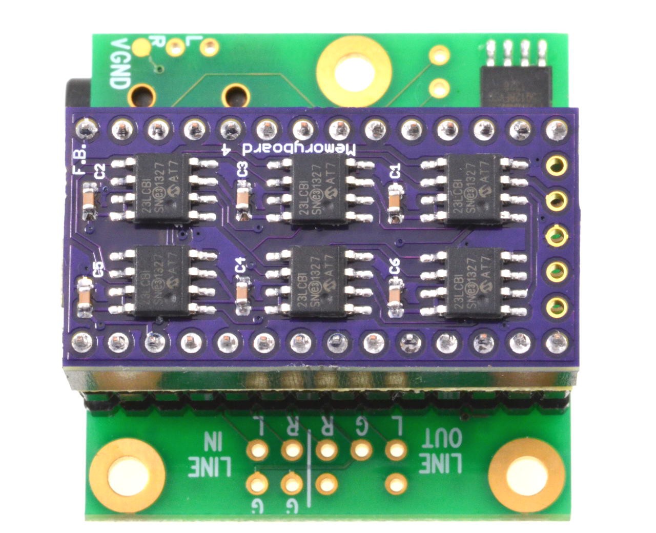
The audio library (latest on github) now supports this hardware.
Here's a simple test where it delayed a beep sound, with copies output at 8 and 9 seconds.
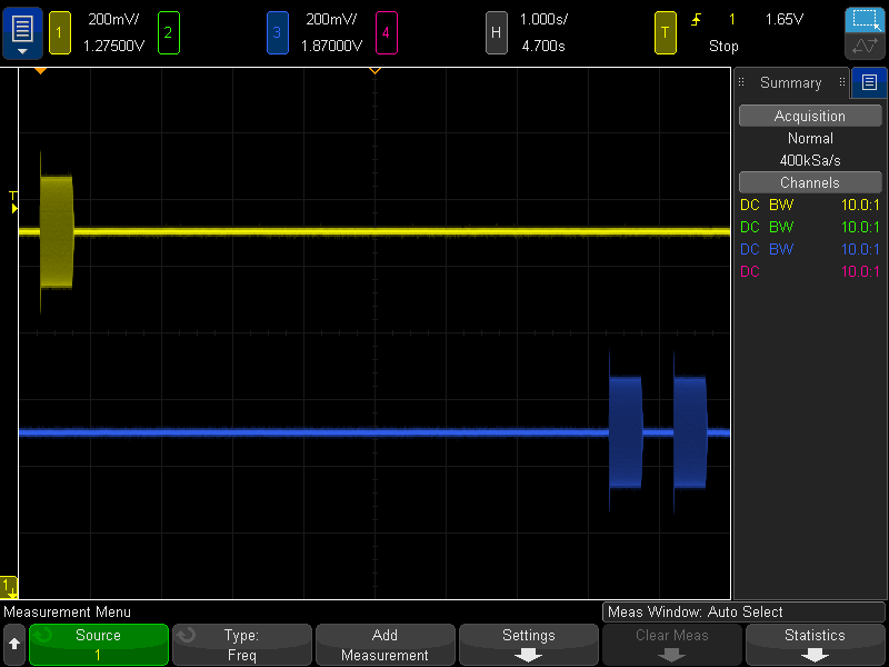
Sound delays this long are really surreal. Delays in the 1-2 second range are about as long as our brains are ever used to hear in the natural world.
It's like nothing happened, like the project is doing nothing and not working and you give up waiting (at least it's way beyond my attention span for stuff working) and then there's the beep, exactly like it was several seconds ago!
Here's a demo of the new delay line feature, using external ram chip(s).
Thanks mostly to Frank B, we now have direct S/PDIF output from the Teensy Audio Library!
Here's a detailed blog article.
You can get optical TOSLINK digital audio with a $1 connector (Digikey 1080-1434-ND) or just a red LED shining into the optical cable.

In the photo above, the TOSLINK connector is mounted on this OSH Park PCB (under $2 for three of them).
The S/PDIF output is also now supported by the Audio System Design Tool, so you can just connect it to whatever complex audio system you like, to get S/PDIF digital output!
Here's the lengthy forum thread where this development was discussed.
Version 1.0, the first stable release, is now available.
http://www.pjrc.com/teensy/td_libs_Audio.html
Here's Hack-a-Day's coverage.
I'm sure anyone familiar with Arduino must be skeptical.
16 bit, 44 kHz streaming, not just 1 input or output for monophonic playing, but many simultaneous streams between dozens of virtual objects, with I2S digital audio streaming to an external ADC/DAC/Codec is FAR beyond what anyone has done on the Arduino platform before.
The "catch", or the key enabling technology, is the 32 bit ARM Cortex-M4 processor and Freescale's eDMA engine (on Teensy 3.1). This more powerful hardware, and a LOT of work in this library, make this tremendous increase in audio streaming possible.
ARM's Cortex-M4 processor has special DSP (Digital Signal Processing) instructions, which this library uses to dramatically speed up computationally intensive operations, like filters, mixing, linear interpolation, etc. It also has a burst memory access mode which accelerates transfer of small groups of audio samples.
The DMA engine is the other key enabling hardware. Without DMA, the CPU would need to handle each piece of data streaming on & off chip. Even on a fast ARM microcontroller, 44100 interrupts per second burns a lot of CPU time. Fortunately, the DMA engine can automatically move data between memory and the on-chip hardware. It generates an interrupt only when half or all of a 128 sample block is complete. The fast ARM processor can easily handle 689 interrupts/second. It also allows other interrupt-based Arduino libraries to used together with audio. As long as their interrupts complete reasonably fast (as most do), they don't cause audio glitches, because the DMA engine keeps the data flowing.
The library is designed to make efficient use of the hardware. The live streaming between objects is actually implemented by passing shared, reference-counted buffers. When the output of one object streams to the inputs on several others, shared copy-on-write memory management is used, to avoid memory-to-memory copying as much as is possible.
Of course, there always are limits. This is a low power microcontroller, afterall. The library efficiently implements CPU usage tracking on all objects. Your Arduino sketch can query each object, to get its current and worst-ever CPU usage, or the total usage for all objects.
For example, the pink noise generator takes 3%. The 1024 point FFT object uses bursts of 52% (a future version may smooth its usage over time). Simple effects like the AHDSR envelope are well under 1%. The Synthesis/PlaySynthMusic, which generates 16 simultaneous waveforms, routed to 16 simultaneous AHDSR envelopes, and then mixed down to stereo output by six 4-channel mixes, consumes a worst case CPU usage of 31%.
I've been working on this library for about 1 year, and dreaming & planning it much, much longer. It's getting close to *finally* a 1.0 release. So many other audio projects have required PC-class hardware, or suffered low quality sound and difficult limitations on what an Arduino sketch can do while sound plays. I'm really excited to finally have a solution for the world that will make high quality sound easy on microcontrollers!
Create an account to leave a comment. Already have an account? Log In.
The forum conversation is about community published code, not software published directly by PJRC. So far, I have not had time to even try using that code. I hope you can understand I can only directly support software PJRC publishes. In time PJRC very likely will incorporate that software or something similar... but right now we only publish and support USB audio for bidirectional stereo. For help with that special 8 or 16 channel audio code, ask on that forum thread. And please understand, it is free community published code which is only supported by the whim of the author who has no financial incentive to help you. Your odds of useful help really depend on your ability to make a good impression. Generally speaking, people have a good impression when you show you're making a strong effort to investigate or solve the problem... so when you compose another message on the forum, consider adding photos or more info that shows the specific things you're trying. Even if not strictly necessary from a technical point of view, remember you're dealing with real people who aren't making money from the free software they're sharing.
hi, stumbled across this and looked up the CS42448 out of curiosity. The mfr. indicates this is obsolete. Find chips.com shows some distributor stock, get ‘em while they last!
Paul, can both pin 1 and 2 of the CS42448 be pulled down by single 100k resistor?
Pulling both pins 1 an 2 down with resistors when only one CS42448 is used is the confirmation I needed. Thanks for the quick response. I knew these pins configured I2C addresses but didn't know why you included the jumper option since TDM mode seemed the better choice over I2C for 8 DAC outputs and 6 ADC inputs.
There is no choice to be made. You can't have (good) audio streaming on I2C (and CS42448 doesn't provide any audio even low quality on I2C), and you can't configure parameters using TDM. This is why CS42448 and most other audio codec chips have both I2C and I2S/TDM. You don't get a choice of which to use. Each has a specific non-overlapping purpose. Some simpler chips let you do basic config by connecting pins high or low at startup, rather than requiring I2C communication. But no audio codec chips give you configuration over TDM or I2S. It simply isn't part of those simple audio streaming protocols.
Paul, we are building a variant of the T4 CS42448 board using the newer 4.1 CS42448 as a guide but need a better understanding for how the connections to pins 1 & 2 of the CS42448 varied between the two for TDM mode. The newer version had jumper pins for AD0 and AD1 but cannot find how these are used. Please help.
Thanks
The ADDR0 and ADDR1 jumpers are meant to configure the I2C address. If using only 1 CS42448, just leave them off so the pulldown resistors configure for the normal/default I2C address. Like all I2C chips, if you connect more than 1 of them, each needs a unique I2C address. These address pins are only for the I2C protocol used to configure the chip. They have nothing to do with TDM.
I found this while researching for a project I'm thinking about starting where the goal is to make an audio transceiver of sorts. I have to read an analog signal and convert it to digital, run any compression/transcoding/other processing on that signal, then send it through an rf transmitter to its pair; all the while receiving data and going through this process backwards.
My question is where do I find a 16bit dac capable of reading a 192+ kbps @ 44khz audio signal- I have no idea what I am doing, and is a teensy capable of doing all of the above concurrently & constantly without a hiccup? and how? A little guidance should be all I need right now.
I am also new to this platform so if I'm in the wrong spot please correct me.
Hello, it is a great idea with the 16+16 soundcard based on the CS42448!
I'm thinking of using it as an alternative electronics ATE system. All stimuli could be edited and saved as PWL -> wav files, which could be triggered simultaneously. The measurements could be defined in PWL files, too. (for voltage /or current measurements). -I would like to modify the inputs with PGA/attenuators (1/2, 1/4, 1/8, 1/10, ..), all inputs DC coupled and symmetric (i.e. +-2.5V). A sampling rate of around 1kHz-10kHz would be sufficient for this purpose. -Any idea if this would be feasible?
Hi! Sir Paul Stoffregen ! It's Muhammad Umar Here, from Pakistan. Recently I have got Arduino Teesy 3.6 & also its Audio Shield. Firdt of all, I thank you & Miss Alysia Dynamik for the Workshop on Arduino teensy. I have learnt alot of things from that Workshop. Sir! I am facing an Issue from some days, that there is access issue with PJRC Forum, because every time I visit to that forum, the IP Address of my Laptop got Banned from the Side of the Administrator, I a have tried to contact with the Administrator but still not Working because the Site Needs Login Credentials. Can you please guide me for the Solution of this Issue. Here is my Email, if you can send me some tips for getting Access to the PJRC Forum;
Hello, is the generated code portable to other processors that have I2S, FPU, or DSP instructions? Also can depth be modified up and down ? I own several of your products but haven’t used the Audio Shield yet.
No, not really. The input & output code depends on the specific I2S hardware and DMA engine on Teensy 3.x. Many of the data processing features depend on the ARM Cortex-M4 DSP extension instructions. It won't run on lesser ARM cores, nor on non-ARM chips like ESP.
The I2C address jumpers were meant to be used when using this CS42448 board with another project I never completed, which would have allowed 2 to work together for 16 channels of 16 bits.
https://hackaday.io/project/176368-dual-interleaved-cs42448-chip
The idea was also to be able to use both TDM ports on Teensy 4.x this way, for a total of 4 CS42448 boards. Maybe someday I'll revisit that TDM interleave project. But even without it, you could use 2 CS42448 chips with a Teensy 4.0 or Teensy 4.1 by just connecting each to the 2 TDM ports. In that case, if you connect both of their SDA & SCL signals to the same I2C port, like any I2C chip, each must have a unique address.
TDM isn't an address-based protocol like I2C. The only way to put more on the same TDM port is with an interleave board that puts the data from extra chips into the bit slots not needed for the other chip. Much harder than just setting an I2C address.
Hi Paul, can I ask what you used to design your web-based GUI tool? I have a project that needs something similar, where the users draw a graph between different shapes, but I'm still quite new to web-based GUIs. Thanks, and great work!
It's called Node Red. Here's the site.
Here's a link to the original proposal to use this, back in the summer of 2014.
https://forum.pjrc.com/threads/24793-Audio-Library?p=50653&viewfull=1#post50653
This message was the very first screenshot as I started to hack (or "butcher") the Node Red code.
https://forum.pjrc.com/threads/24793-Audio-Library?p=53238&viewfull=1#post53238
Become a member to follow this project and never miss any updates
 NormalL User
 Bela Platform
 Henrik Langer
hi Paul
Not sure if you are noticed that we are struggling with the USB interface compatibility of the CS42448 on Mac. We started some tries few months ago but without success, any chance you could spot some solutions? many thanks.
https://forum.pjrc.com/index.php?threads/usb-interface-for-multi-channel-outputs-not-just-stereo.70176/page-7