So, being my first PCB design to be manufactured, this board has a couple of mistakes. The first, is that the power and I/O header holes are slightly too small because I used the incorrect KiCAD footprint. This was solved by forcibly jamming the header pins in the holes, which is definitely not a very good fix, but it works. The other major mistake was that the area for a USB MALE A plug actually had the pin0out of a USB female plug in the footprint, so if I want to use a USB MALE A plug, I will have to solder it on the other side of the board. Luckily, I included both a Mini-USB B port option as well as the USB MALE A plug, so I did that and got some practice with SMD connections.
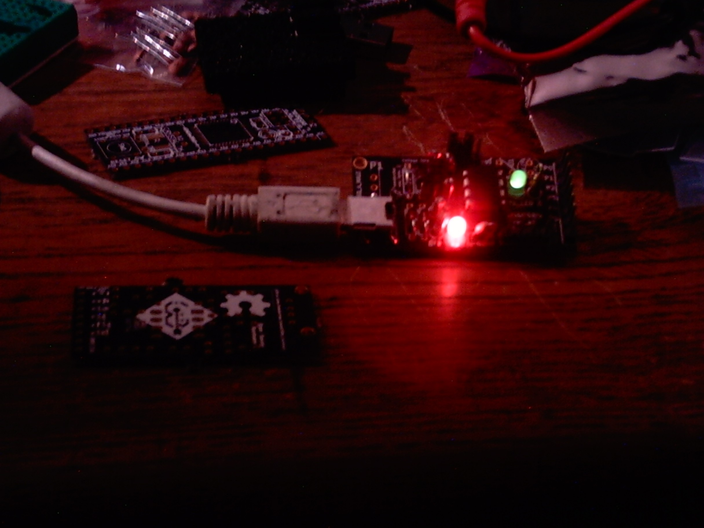
Well, here is a picture of the board successfully running a classic toggling led program:
The littlewire firmware works on it as well, and I have been able to upload programs to my AVR_board_m8515 with it.
 Ethan Durrant
Discussions
Become a Hackaday.io Member
Create an account to leave a comment. Already have an account? Log In.