DainBramage
-
It's Alive!!!
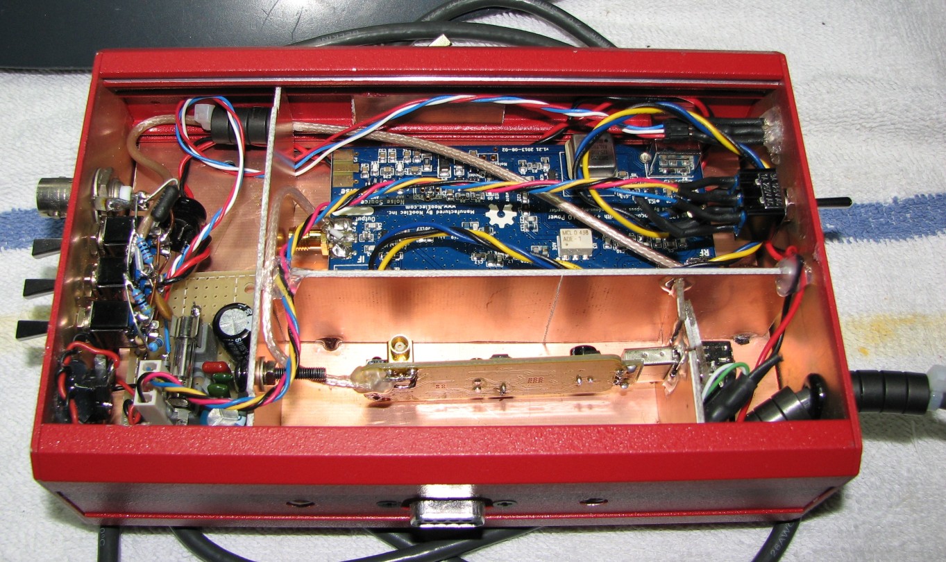
05/09/2015 at 21:31 • 0 commentsI thought for sure that my Ham-It-Up had perished from mishandling, ESD, or just plain bad luck. Fortunately, I was wrong. After a bit of testing confirmed that the upconverter was still functional, I got to work patching up the holes in the case with some copper tape and putting the thing back together.
![]()
And a bit more on the chassis:
![]()
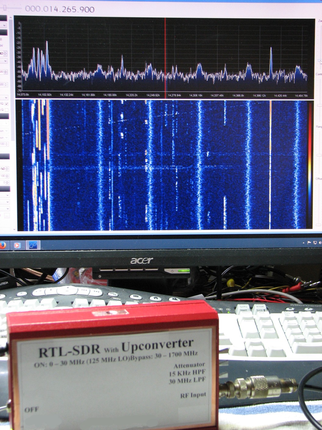
And we have a working unit again, here listening in on the 20 meter ham band:
![]()
On the right side of the unit are the switches for the 3 filters, which are in series, unfortunately. Someday I will replace the switches with DPDT ones so I can wire them up individually. For now, however, I'm just glad that the thing is working.
Sort of...
After working on writing this log for a bit, I found that the thing started randomly losing communications with the computer. The SDR# waterfall would freeze, and I had to cycle the SDR's power to fix the problem, only to have it crop up again a few minutes later. It even froze up during For Whom the Bell Tolls! Seriously, during Metallica's best song? It could just be a loose connection, or it could mean that I need to replace the SDR board. I hope it's the former. Even though RTL-SDRs are cheap, and I do have a couple more lying around I could shove in, I'd rather not start going through them.
Another ugly fact is that despite all of the work put into isolating the RTL-SDR and upconverter, and all the effort put into shielding them, their performance is not significantly different from what I saw when both devices were completely unshielded. If I am to be honest here, I recommend only putting minimal effort into shielding your own RTL-SDR setups. It just doesn't seem to do much for them, unless you are battling a strong local source of RFI. Even then, it will still come in through the antenna. Switchable filters can help there, but I find that I only use the filters to differentiate between external signals and internal RFI, as when both filters are in and the attenuator is on, the thing is essentially rendered deaf.
All this effort, and I ended up with what it basically just a convenient carrying case for my RTL-SDR. Oh, well. I learned a lot from it. Hopefully you can as well.
-
Still on Hold
04/29/2015 at 15:50 • 0 commentsThis project is still on hold while I work on other things that include, in no particular order: organizing my parts supply, organizing my bench, re-working my 12v power solutions (for ham radio), helping a friend get started with electronics, writing a monthly column, and a hundred other things.
I will get back to this project in time, though I am still waiting for my supply of magic blue smoke to arrive. I may need to contact the seller and find out why it hasn't arrived yet.
-
Watch This Space...
03/09/2015 at 05:10 • 0 commentsI've purchased some parts for the Junk-Box SDR, now I just need to spend some time working on the thing. I'm a little worried that I might have damaged the Ham-It-Up at some point, so step one will be to test the upconverter. If it does turn out that I've somehow killed the thing, I don't know what I will do if that's the case. I just hope I'm wrong about this.
-
More to Come
01/30/2015 at 19:38 • 0 commentsI haven't forgotten this or shelved it. I've spent the last few weeks thinking about this and I think I've come up with a solution. I just need to get the parts to make it match what's in my head. What parts? A couple of DPDT toggle switches, a 5v relay or two, and a liter of magic blue smoke.
-
One Step Forward, Two Steps Back
01/04/2015 at 23:16 • 0 commentsIt's funny how no matter how much effort you put into doing something carefully, you will always end up being surprised by how badly it can go wrong.
I decided that I should remove the new power supply circuit that I had added to the Junkbox SDR when I determined that the vast majority of the RFI I was trying to battle was actually internal to the device. There was also the slight issue of bricking the RTL-SDR when I plugged the data lines into the computer without first turning the power on. Fortunately, the module came back to life after a while. I do have a couple of spares, but I didn't want to be burning them up all of the time, especially not for such a stupid reason.
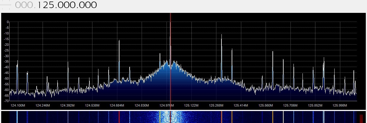
Here is an example of the RFI seen that is internal:
![]()
This is with a 50Ω terminator across the input. This is actually the 125 MHz local oscillator from the Ham-It-Up upconverter board, which is still active despite the fact that the unit is in bypass mode. This same pattern shows up every 125 MHz up as far as 1.25 GHz. I may have to re-think the whole project. At the very least I need to figure out a way to switch the upconverter completely out of the circuit and power it off when in bypass mode (using the RTL-SDR only).
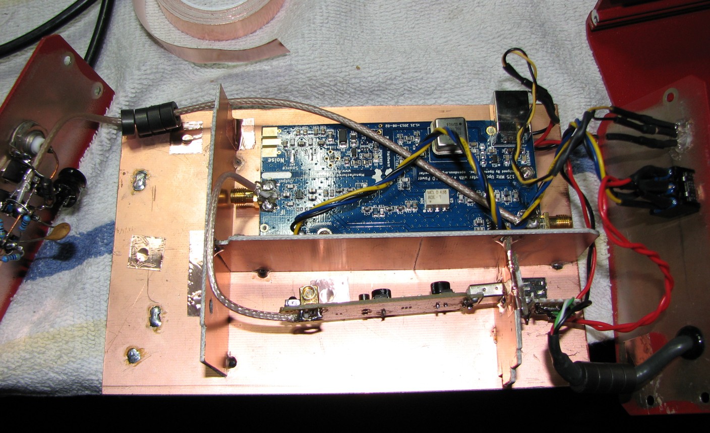
One improvement I managed was to make the filters actually function by actually soldering them up the way I had originally intended, instead of the hurried miswiring I had done before. It looks like total crap, but at least it works... Sort of. The filters can only be switched on in sequence, rather than individually. I figured out a circuit that will fix this problem, but I'll need to pick up some DPDT switches to replace the SPDT ones that are there now.
The work progresses, slowly. My intention is that this project end up being a simple to use general coverage receiver. I'm heading in the right direction, but the title of this log entry says it all.
![]() Work in progress...
Work in progress... -
Warts and All
11/16/2014 at 01:09 • 0 commentsWell, I thought I might actually have the project done by now. After all, it is all buttoned back up and fully functional. ...Almost.
After spending many days designing, tearing apart, reconfiguring, thinking about, and generally messing this project royally up, I finally put the thing back together and turned it on. That was when I realized all of the mistakes I had made.
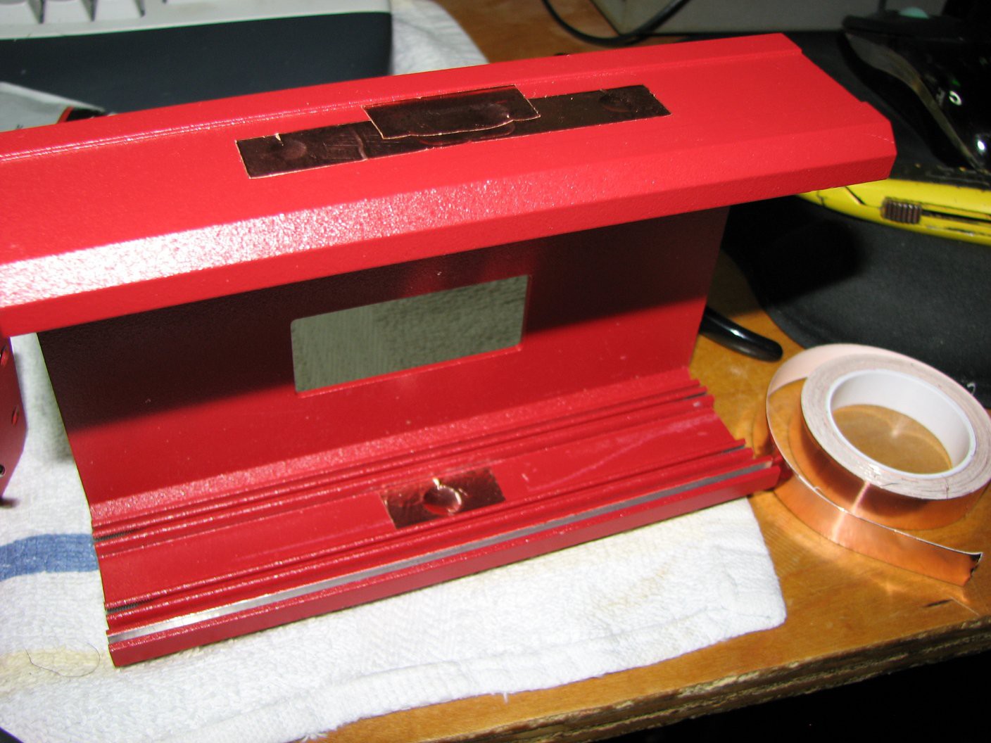
First off, a recap. I had intended to make a number of changes to the original Junk Box SDR, so much so that I almost considered calling it the Junk Box SDR 2.0. However, that sounded extremely lame, considering that the main electronics (the SDR and upconverter) were unchanged. The changes that were actually made were: better shielding by filling in some of the holes, completely isolating the internal power from USB by adding a 12v to 5v DC-DC converter (a simple 7805 with plenty of smoothing caps) and drawing power from the Astron RS-35M that I use to power the rest of my ham radio gear, isolating internal components from each other, adding switchable filters and an attenuator, adding a bi-color LED to indicate which mode the SDR was in (upconverter active or bypassed), and generally cleaning things up and doing a nicer job of things.
Here are my more obvious mistakes: The filter circuit I designed never stood a chance of working due to an oversight so obvious I am too embarrassed to share it with you. The photo I posted is probably sharp enough for you to figure it out. Total facepalm moment. Speaking of facepalm moments, I had a similar feeling when I realized why the bi-color LED showed up as orange instead of either red or green. Yup, I'm feeling pretty stupid right about now.
The one thing I'm not blaming myself for is the discovery that the SDR and upconverter are actually generating much of the noise I was hoping to be able to get rid of with this project. That was an unexpected blow, but one I would not have been able to discover without going through all of this trouble.
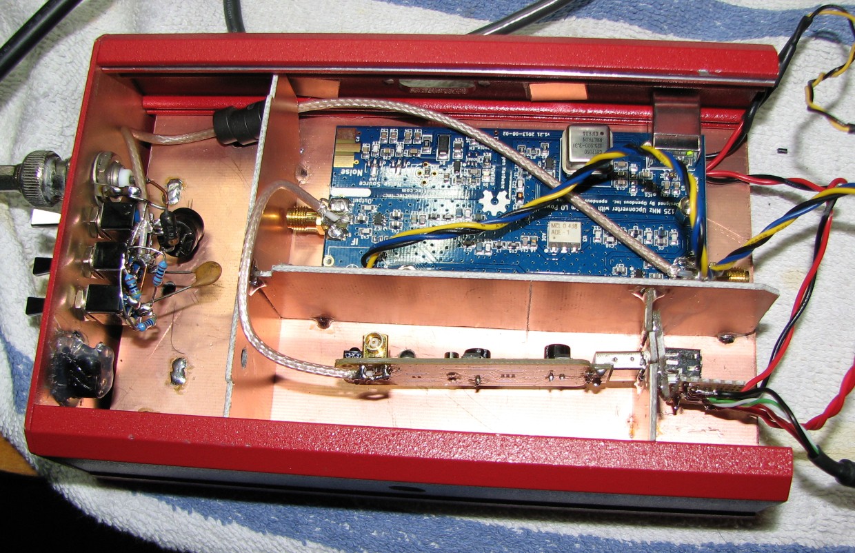
Here it is, warts and all (minus the top cover):
![]()
Now that I've made a complete fool of myself in this somewhat public forum, I can start to work on coming up with fixes for the various problems I have created. However, I am feeling a bit burnt out today, so the Junk Box SDR will go up on the shelf in front of me until I feel like cracking into it again. I hope those following this project will be patient with me. I'm also open to suggestions, provided they can be achieved with little to no monetary expenditure.
-
The Junk Box SDR is Coming Along
11/12/2014 at 16:39 • 0 commentsI've been making some progress in re-building what I am now calling the Junk Box SDR. As I mentioned the other day, I have built a small 5v power supply. I have since added another zener diode on the 5v side to protect that side of the supply (from what I don't know, but it's there nonetheless). I have also started wiring up the connections to the power supply board.
I'm trying to reduce USB noise as much as possible, so in addition to adding a number of ferrite beads to the USB cable, I am bringing it into its own small compartment. The two power wires and the cable's shield are dead-ended and covered with heat-shrink, and the two data wires are connected to a female USB connector that will be supporting the actual SDR dongle. I've also brought power wires from the power supply board into this small compartment, so that the SDR dongle can now be unplugged and removed more easily, should it need replacement (I'd still have to unsolder the antenna lead).
I've finalized the filtering scheme: I have one high-pass filter with a cutoff frequency of 1.5 MHz to reduce interference from local AM radio stations. I have a low-pass filter with a cutoff frequency of 30 MHz to reduce front-end overload from the many local FM radio stations. Lastly I have a 50dB pi attenuator. All of these are switchable, so they can be used as needed. The only issue I have is that there is no easy way to make these work from the front panel. Actually, the Junk Box SDR doesn't really have a front panel. This is somewhat annoying to me, and if I ever do one of these again I will design it from the ground up so that all of the controls are on one side and all of the wiring is on the opposite side. It's a bit messy as it is now, but it is a junk box project, so I've had to make do with what I could get my hands on. With the exception of the SDR, the upconverter, and the switches, everything in the Junk Box SDR actually came from my junk box, hence the name.
More photos to come.
-
Progress
11/09/2014 at 02:51 • 0 commentsThings are rolling along, slowly.
I've mostly been doing planning and testing, which involves a lot of running up against my own limitations.
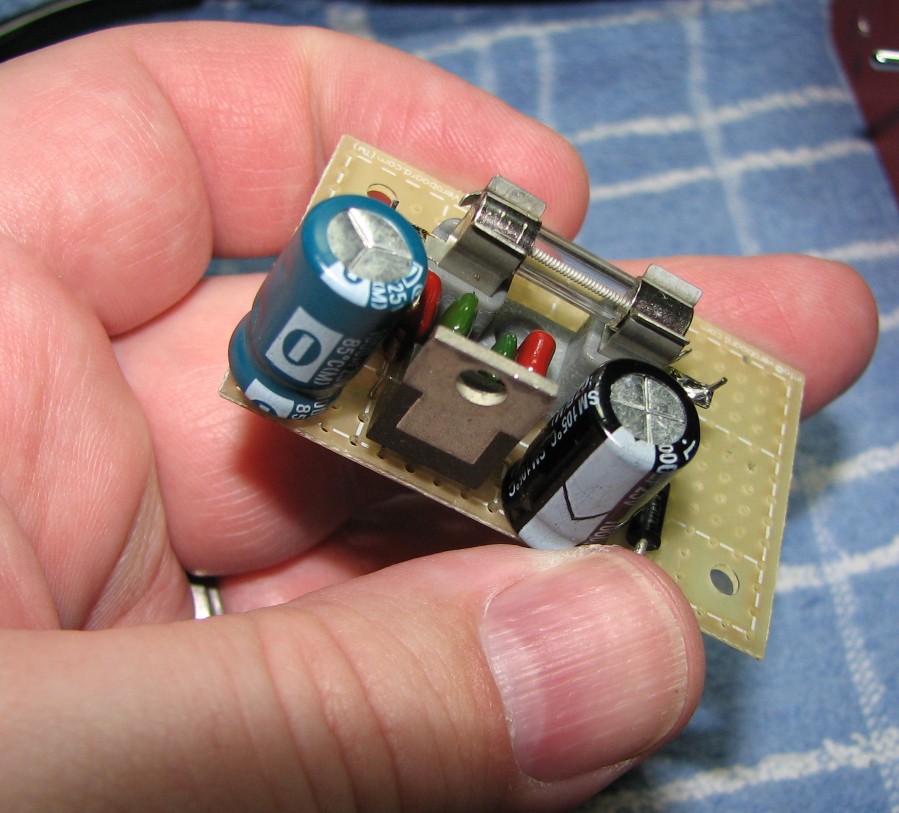
I have decided to isolate the RTL-SDR and upconverter boards from the computer (read: noise source) as much as possible. I don't have access to a USB isolator (yet), so I've decided to give the box (I need to come up with a name for this thing) it's own 5v power supply based on an LM7805 linear regulator. Power will come from the same Astron RS-35M that powers all of my other ham radio gear. I've already built the 5v supply board, and tested it on my Rigol scope. It shows less than 5 millivolts of ripple, so it should work well. I will also be using the case as a heat sink for the 7805, so I should be able to pull between 1 and 1.5 amps without risking damage to the regulator. I've also included a 21 volt zener diode along with a 2 amp fuse, a combination which will provide over-voltage, over-current, and reverse polarity protection.
I will include a circuit diagram later, but for now here is a closeup of my fat fingers for your viewing pleasure. Oh, and the supply board also.
![]()
-
Equipment Failure Workaround
11/01/2014 at 15:58 • 0 commentsOkay, so the trusty old Singer CSM-1 isn't so trusty, but I did find a workaround that allows it to work perfectly. Almost.
It's 10 Hz off, but hey, you would be too after 40 years of service.
I did the first of the measurements last night and was absolutely blown away by the raw sensitivity of the amazing little SDR. Starting at 100 KHz with the upconverter active (so we're looking at it's sensitivity as well), the sensitivity was -62dB. Not a very good start, but we're at a pretty low frequency. Most wide coverage receivers are crap down there anyway. I started testing every 100 KHz, and the sensitivity went up quickly. By the time I got to 1 MHz, it was up to -100dB (up to?). From 3 MHz and up, the sensitivity was at the maximum I could measure with the CSM-1, -110dB. That's as sensitive as my Yaesu FT-857D, which cost an awful lot more than that $20 SDR module!
At 70 MHz the sensitivity started to drop off, until I realized that I was reaching the limits of the Ham-It-Up upconverter. I switched it out of the circuit and continued on all the way to 550 MHz, the upper limit of my CSM-1 (the SDR measured -110dB at all frequencies). Technically it can go higher using harmonics, but the output amplitude of those harmonics won't be at the calibrated level. Good for frequency testing, but not for precisely measuring sensitivity.
So, in it's current configuration, this cheap-as-beard-dirt SDR module is very, very sensitive. However, it's still wide open and noisy as anything.
More testing later, when I start playing around with various filtering circuits and ideas.
-
Equipment Breakdown
10/31/2014 at 14:42 • 0 commentsI finally sat down with my RTL-SDR in hand to do some starting measurements before tearing into it. I fired up my trusty old Singer CSM-1 service monitor only to find that it was not putting out a clean tone on frequency, and was generating very strong signals every 4 MHz or so for roughly 20 MHz on either side of the center frequency. Also, the center frequency signal, in addition to being dirty, was also very weak at roughly 10dB above the noise floor (much of that noise was coming from the CSM-1 itself).
Since the attenuator is passive and the last device in series before the output port, I thought I could at least use those strong signals to do my testing. Then I realized that I have no way of accurately knowing what the baseline amplitude of those signals was, so I can't use them to measure receive sensitivity in the SDR.
I've spent the last two days tearing into the CSM-1 with a screwdriver in one hand and the service manual in the other, but I have been unable to determine what the problem actually is.
If anyone has any specific knowledge about this issue, I welcome your feedback. I really would like to have my service monitor working again, as I don't have any other equipment that can stand in for it.
The rebuild of the RTL-SDR may be on hold for a bit while I try to figure this out.
RTL-SDR With Upconverter and Case
The Junk Box SDR: a simple project to illustrate how it is possible to mount and mod an RTL-SDR and upconverter into a case.
 Work in progress...