Close
0%
0%

ZeroCool

An active cooling solution for the Orange Pi Zero

Similar projects worth following
The subject: Xunlong's Orange Pi Zero

The case: an application that maxes out all 4 of the H2+'s cores running at full performance (1008MHz and no CPU governing) while saturating the onboard (GPIO) wifi creates a heat dissipation issue that adversely affects wireless data streaming performance.

The solution: After testing (including clock speed and kernel adjustments), it became clear that an aluminum heat sink atop the H2+ package would not solve heat-dissipation and subsequent wireless data streaming issues. With low weight and cost, a fan was added. As the miniature low voltage fan produced obnoxious noise while running at full speed, I incorporated a switching system to control the speed the fan based on relative temperature of the CPU/enclosure. In early tests, a fan connected directly to the 5V supply rail caused issues with the onboard wifi, causing intermittent signal drop out. This led to the inclusion of some degree of EMF isolation.

Similar Pi fan controllers use a software-based solution that runs on the Pi system itself and controls the fan via GPIO. This was a potential option, but was dismissed due to a few issues, including the added complexity (point of failure) of software running off-board. Opting for an always-on solution that doesn't depend on whether the attached SBC is running means losing access to the system thermal information. As such, our add-on board will need to measure the relative temperature itself, and make a decision based on this measurement to run the attached fan at an optimal speed. Given that noise (and MTBF) are a concern, this would ensure the fan only runs when it gets hot enough to affect CPU && wifi performance.

Due to the very compact nature of the Orange Pi Zero, few of the Allwinner H2+ peripherals are available with usable ports. This presented an additional opportunity in creating this add-on board, as any of these peripherals could be broken out from the included 13-pin header. In the end, I opted for the 2 additional USB ports, the (analog) video out, and the infrared RX.
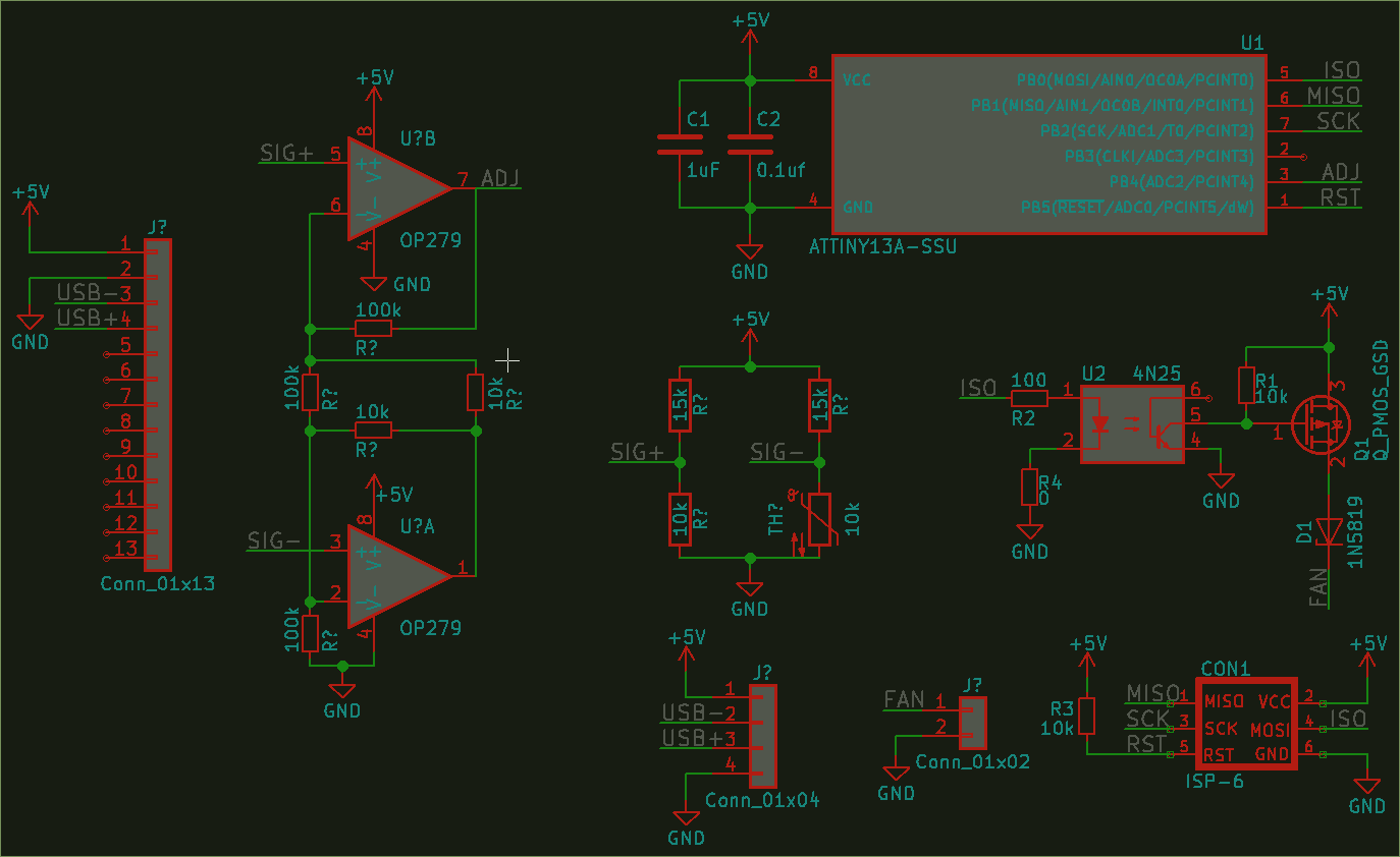
Early schematic revision including amp circuit

To control the fan speed based on temperature, a small microcontroller was selected based on cost and familiarity, along with an instrumentation amplifier and Wheatstone bridge with a radial NTC thermistor potted in a heat sink. The amp circuitry proved to be superfluous, as the MCU's ADC was able to acquire enough information in a simple voltage divider configuration in order to make a fan speed decision.

sbc fan controller.pdf

Schematic for fan add-on board

Adobe Portable Document Format - 37.61 kB - 01/11/2018 at 17:10

Preview

  • 1 × ATTiny13A Microprocessors, Microcontrollers, DSPs / ARM, RISC-Based Microcontrollers
  • 3 × 0805 10k ohm resistor Passive (resistor)
  • 3 × 1.0mm 1x02 (JST ZH) Connectors and Accessories / Miscellaneous Connectors
  • 1 × 1.0mm 1x03 (JST ZH) Connectors and Accessories / Miscellaneous Connectors
  • 1 × Trimmer 20k ohm

View all 12 components

  • Plug your ears, this will hurt

    Chris Slothouber05/30/2018 at 03:25 0 comments

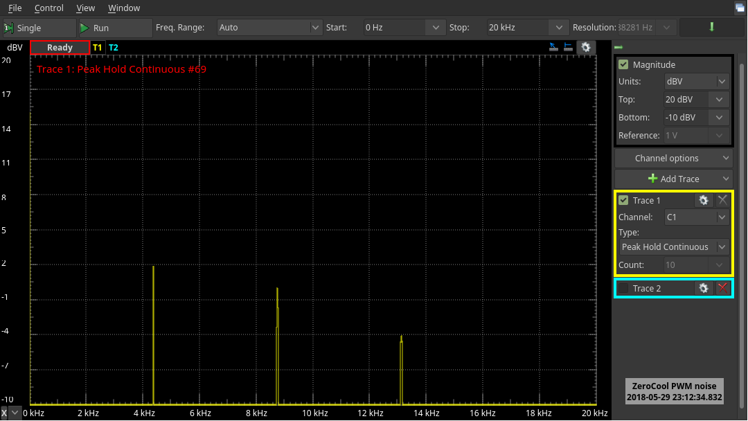
    As promised, here's the frequency analysis of the original ZeroCool firmware running on the Rev B board. As I have been toiling away at finding a new work family, the board has not yet been flashed with the latest firmware. Developed using the breadboarded circuit as outlined in previous project logs, the latest version of the ZeroCool firmware uses a subsonic frequency that avoids any perceptible noise.

    For now, I will leave you with this ear-tormenting graph. Let this be a lesson to avoid audible frequency ranges when pushing a PWM through anything that might act as a transducer, such as a mini cooling fan.

  • Rev B assembly & bring-up

    Chris Slothouber05/24/2018 at 17:36 0 comments

    Although the error-corrected version of my project was delivered by OSH Park a couple months ago, life intervened and delayed progress.

    Following the typical order of operation for assembling a small board such as the ZeroCool, I first soldered the smallest devices to the PCB. This includes the passives, the FET, and then the opto. After I salvaging the MCU from the test Rev A board, the micro and the solderless terminals were affixed using hot air.

    With an early version of the Rev A firmware still resident on the micro controller, I connected the temperature sensor and fan to the board via their respective terminals. 5V was then applied to the board. Expected behavior was observed; adjusting the bias trimpot resulted in a fan speed change.

    Next steps: reprogram the MCU with a more recent firmware that corrects an audible fan whine by moving the PWM frequency outside the audible range.

  • Bring-up: Testing programmer, toolchain, and firmware

    Chris Slothouber02/11/2018 at 21:10 0 comments

       When I set out to build this project, I knew I wanted to keep the design as simple as possible, while achieving

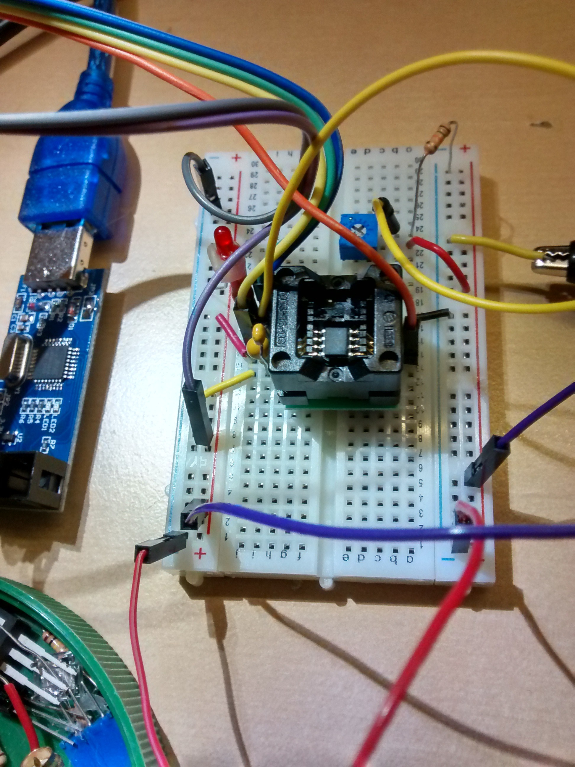
    Prototyping the ATtiny13 SOP package

    more with the expansion board than just running a fan. Using inexpensive materials already on hand kept costs low. Early on in testing the feasibility of this project, I used an ATtiny85 using the attiny core from David A. Mellis. However, with my assembled board now using the tiny85's smaller cousin, the tiny13, my code needed to change. While I could continue to use the Arduino functions provided by MCUdude's microcore, I wanted more granularity of control over the analog input and PWM output than Arduino can provide. With an external editor, I keep the Arduino IDE open solely for its time-saving programming facilities, resorting to the command line when necessary.

       Locating some code from a blogger from Leeds, UK, I was able to modify his PWM LED program to sample my thermistor bridge and output a fan speed appropriate to the temperature level. While I had already tested

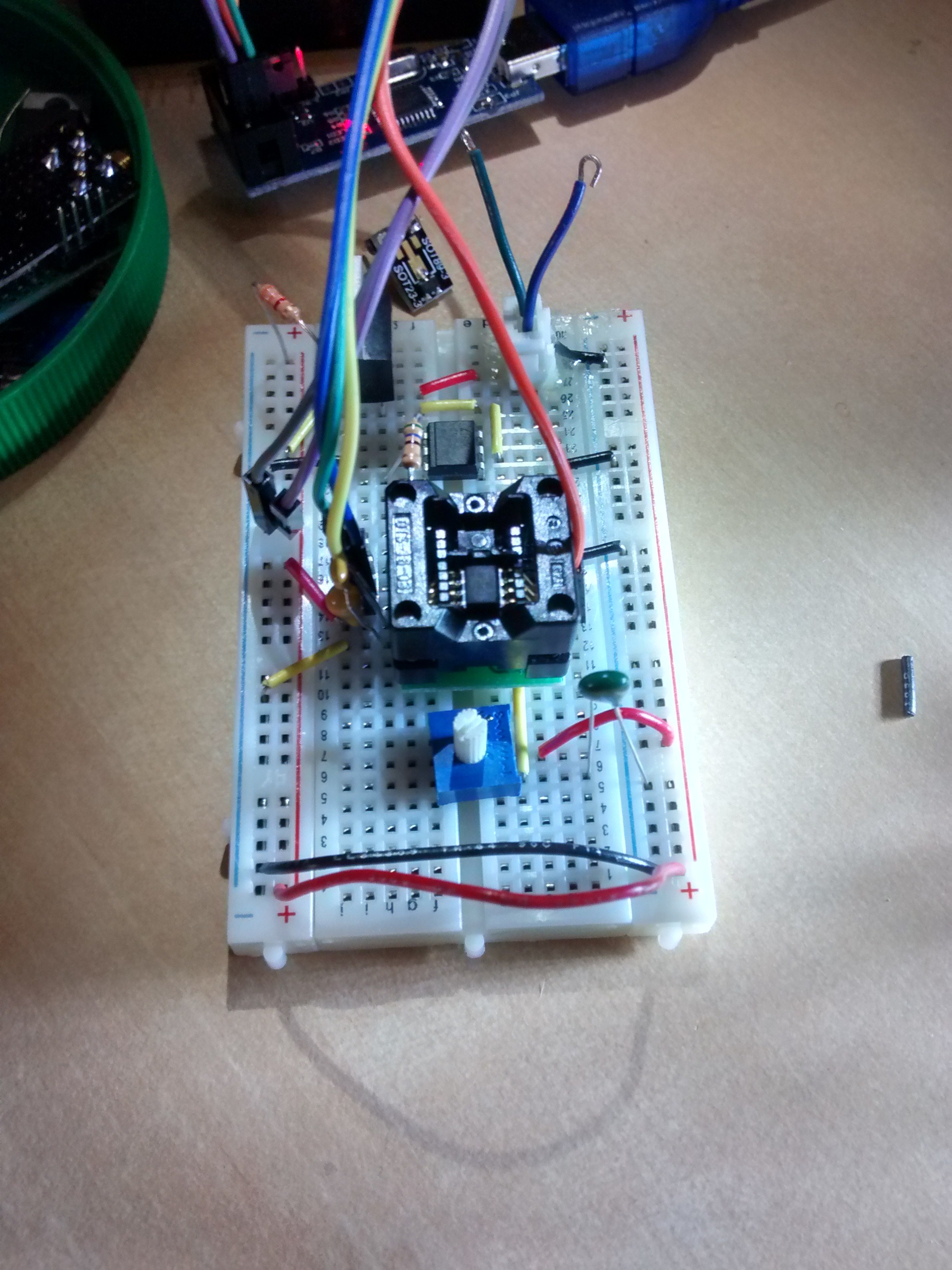
    Circuit recreated using matching components

    the feasibility using of controlling fan speed with Arduino's analogWrite functions, I modified adnbr's code to read PB4/ADC2, match the reading to a frequency corresponding to a particular fan speed, and output this value on PB0/OC0A, which switches an opto-isolator and a MOSFET to control a cooling fan. Having assembled a perfboard with a tiny85 for long-term testing with another SBC, I know this design works reasonably well. 

       After assembling the board, I discovered an error made during the schematic and board layout stage of my

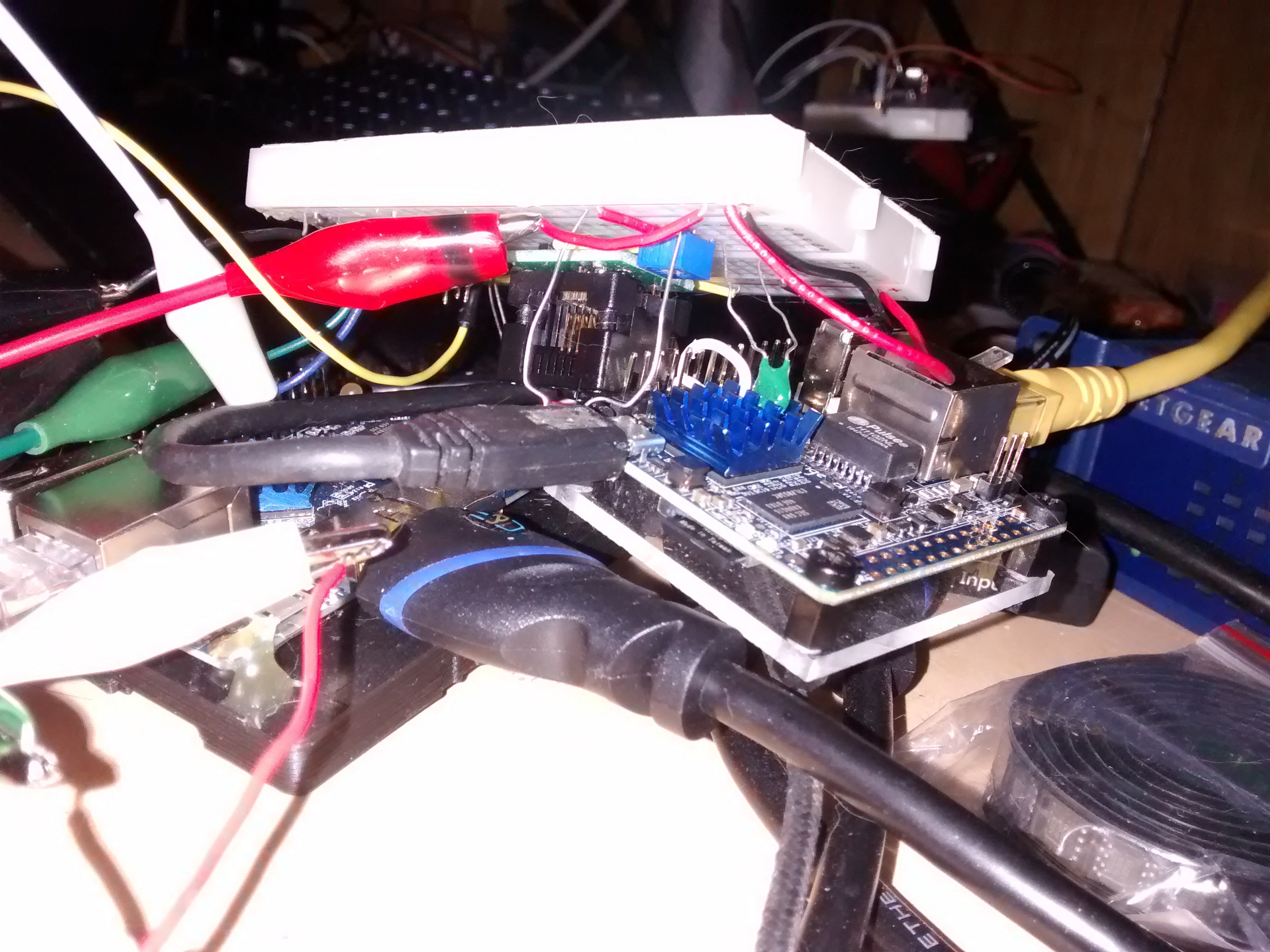
    Acquiring temperature readings for lookup table

    workflow. Specifically, I had swapped around the drain and source pins. D'oh! No wonder the fan was getting full VCC no matter what adjustments I made to the resistive bridge using the trimpot. While the MCU samples the bridge and outputs the correct equivalent pulsed voltage to the 4N25, the first revision of my board design has effectively bypassed the FDN340P, supplying the fan with full voltage at all times. Before making the appropriate changes to my schematic and board layout, I breadboarded the entire circuit again, this time using the ATtiny13 micro controller, and the FDN340P p-channel MOSFET. This allowed me to further test my code with nearly the same components as my board uses.

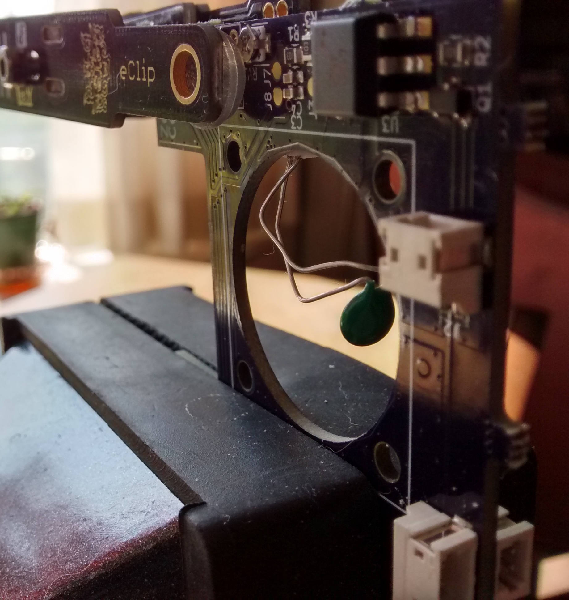
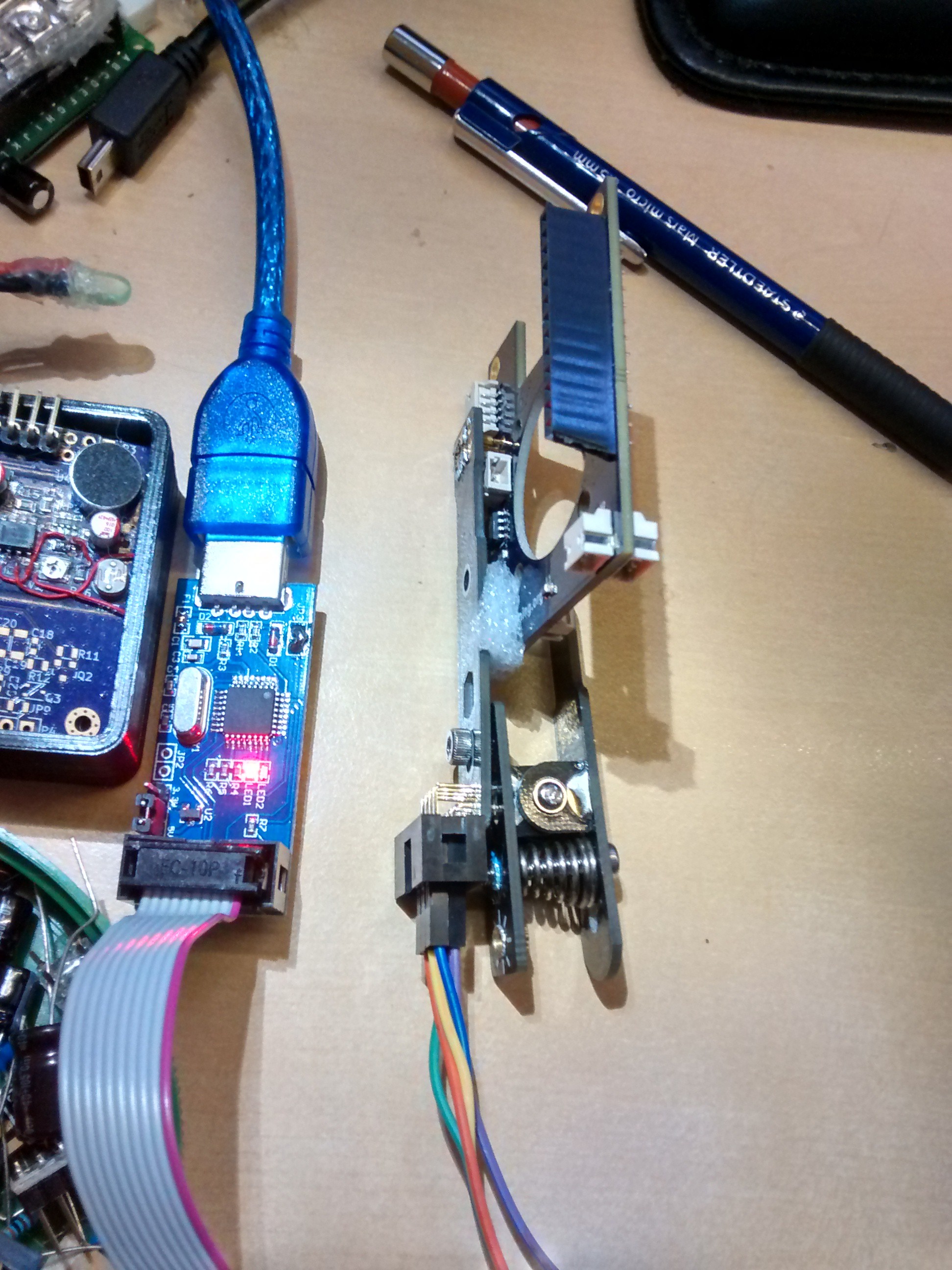
    Using the eClip programming tool - awkward fit

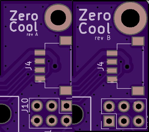
       With the required change to the MOSFET pinout, I took the opportunity to also modify the mounting holes and round off the corners a bit. Given that my programmer is a recent addition to my arsenal, I also modified the 6-pin ICSP header's orientation so that the clip can better achieve a better fit. 

    ZeroCool board revision

  • If the shoe fits...

    Chris Slothouber01/16/2018 at 20:09 0 comments

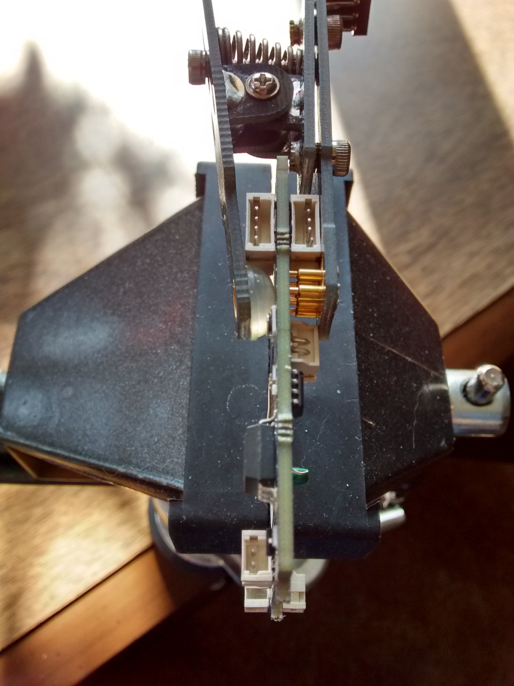
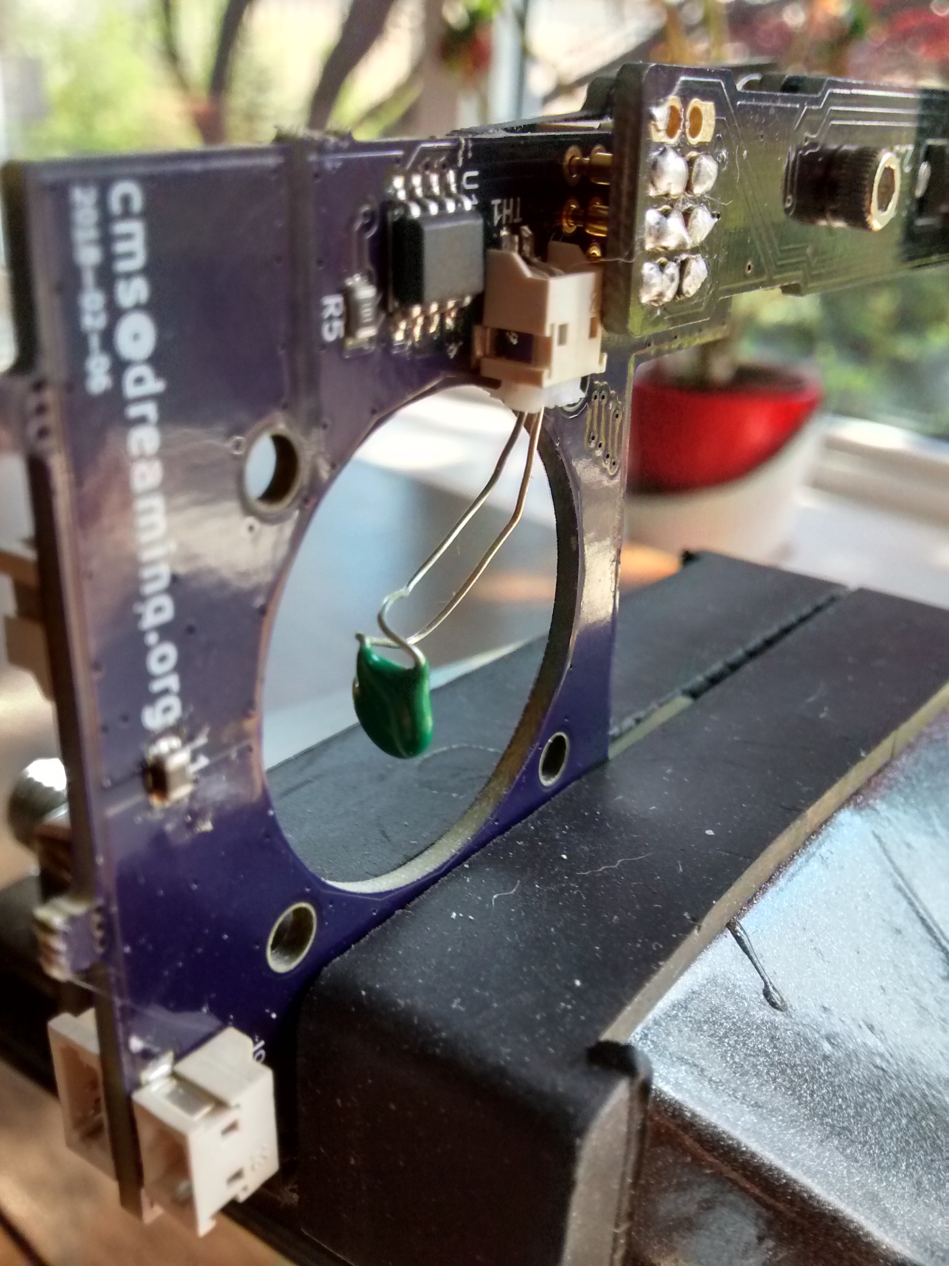
    Fitting with the OPi Zero a success
    Thermistor mating with SoC heat sink

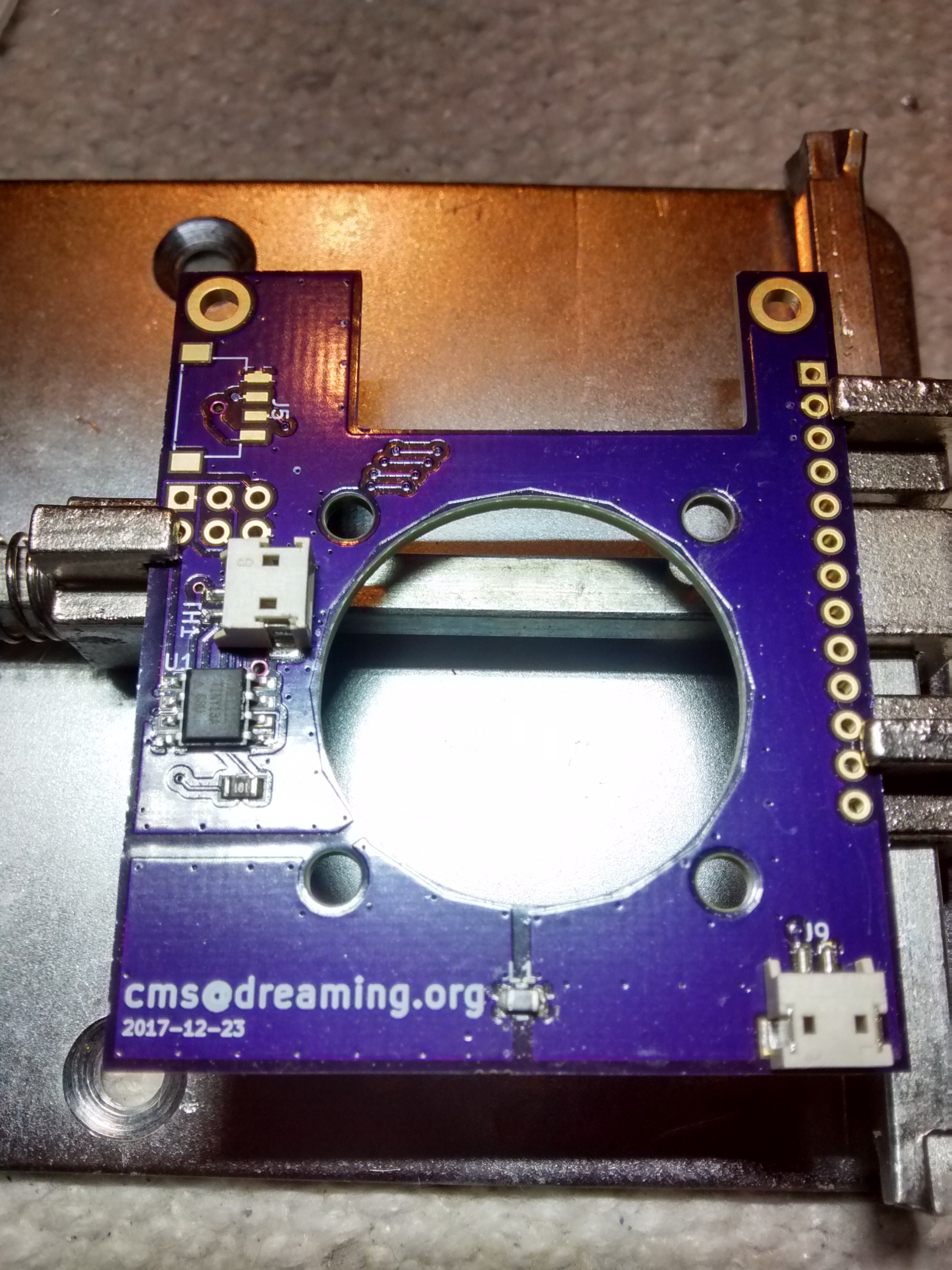
  • Completion of PCB assembly is imminent

    Chris Slothouber01/15/2018 at 01:57 0 comments

    Assembling the rear of the PCB - Waiting for board to cool

    Almost done with the board assembly, one more terminal (J5) to go. My Chip Quik solder paste from Aug 2014 is still viable, though some of its properties seem diminished. Takes a lot of work to get the contacts connected to the ground plane up to temperature, although that may have less to do with old solder paste and more my design.

  • Boards arrived

    Chris Slothouber01/11/2018 at 17:10 0 comments

    Received boards back from OSH Park this week. Checked for mechanical mating to ensure measurements line up with the host board. Everything checks out okay, though the top mounting holes are not quite big enough for M3 screws. Thankfully nylon screws are just forgiving enough to be pushed through with a bit of force.

    To-do: assembly & bring-up.

View all 6 project logs

Enjoy this project?

Share

Discussions

Similar Projects

Does this project spark your interest?

Become a member to follow this project and never miss any updates