This has been a project I've been cooking up in my brain for a while after hearing "You can't fix a bad design with a booster fan" when discussing how the upper floor of my bungalow gets warmer than the lower floor. Before the obvious is assumed, I've done excellent insulation but the heat differential in the house is present in all seasons because the air stratifies and there is insufficient draw from a return duct in the upper floor. During renovation I've placed in the highest location possible based on a recommendation from an HVAC contractor.
I've installed a Fantech 6 inch booster fan in the return duct and have proven that this fixes the issue by running it manually on a constant basis with the main furnace fan. That is similar to how commercial buildings are controlled but for residential purposes it is a little wasteful. The two fans should always be running together but they do not have to be running 24/7. Ideally we are calling them when the thermostat calls for heat / cool.
Additionally the system should be able to trigger the main furnace fan so the combined system can redistribute the stratified air. In a cooling season, this would eventually trigger the thermostat to call for conditioning. In a heating season it would just be actively fighting the temperature differential, potentially reducing the need for heating by redistributing the warm air to lower floors.
I expect that the need for 'boost speed' from this fan may be different during winter vs summer vs shoulder seasons. Also, while the house is vacant, the temperature differential is not so much of a concern. In order to avoid wasting energy and reduce cycles on the system, actively fighting the temperature differential should only be done when needed.
Also the inline fan services my bedroom so I would want to place some speed / noise / cycling constraints on the system at different hours of the day. This is why I'm not just doing this with a relay.
That's a brief description of the project goals. I'm still a bit of newbie when it comes to low level electronics but I've made some decent progress with this. I'm hoping the Hackaday community can help me out with the last few bits and bring it home.
Thanks for stopping by.
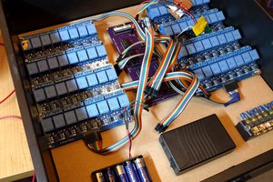
 On a breadboard on my basement finally is a working revision of this. I had spun so many boards and wasted so many components i went back to basics....
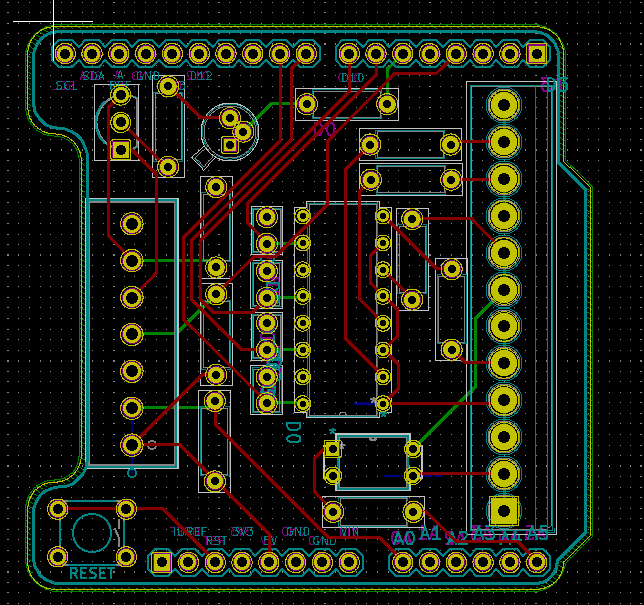
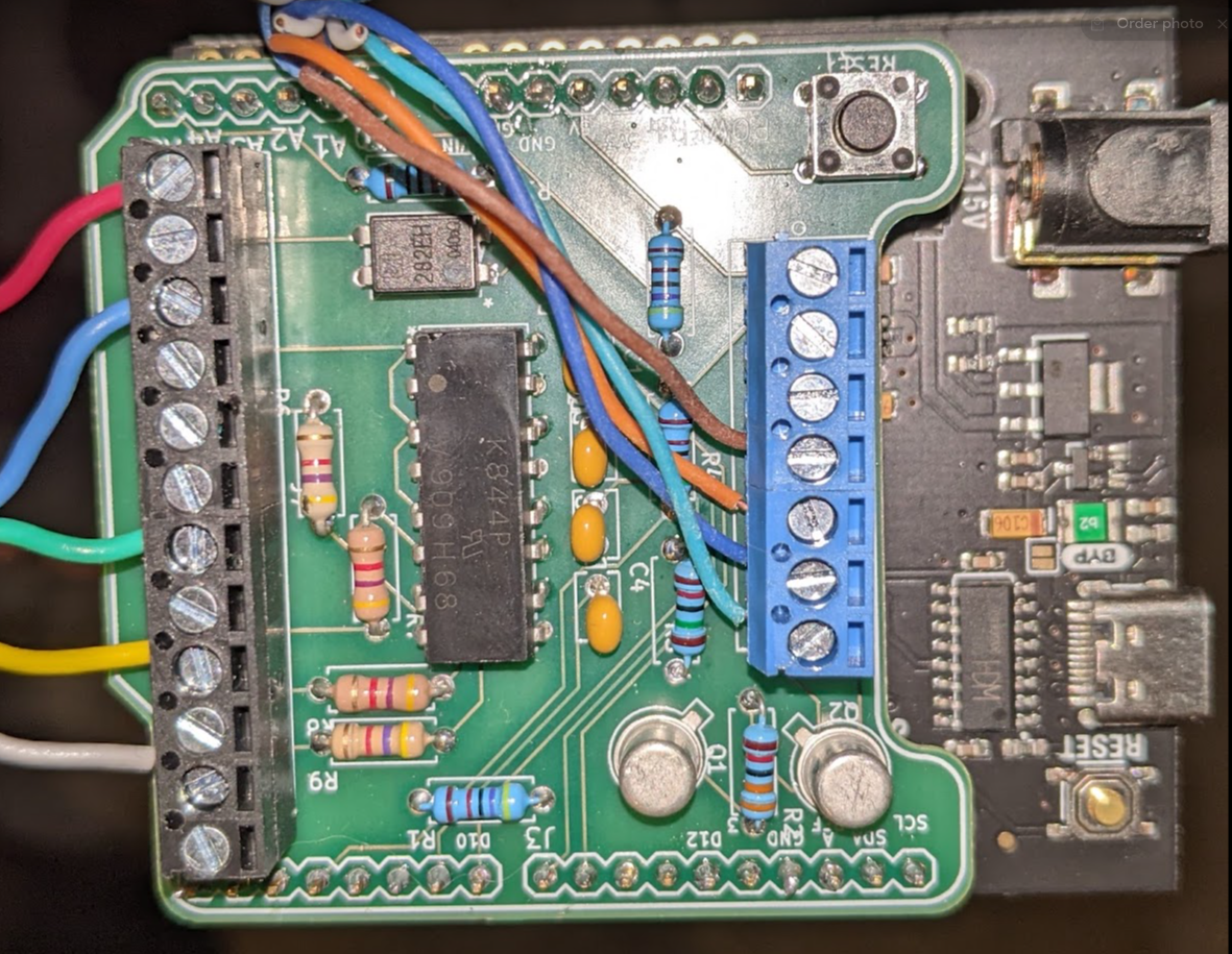
 Here is how I interface to it on the board:
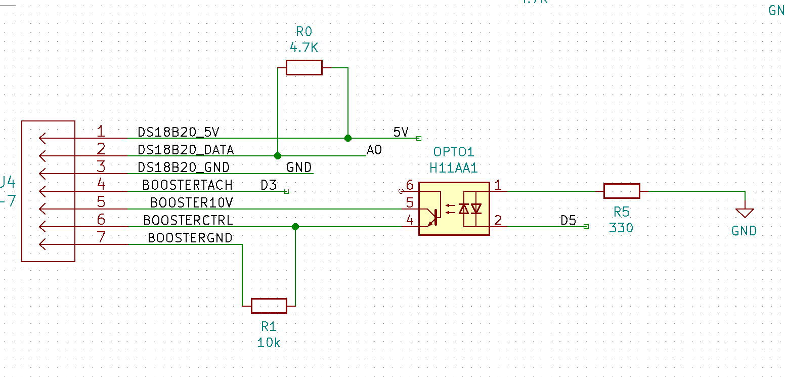

 visualkev
 Paul J R
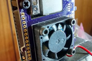
 Chris Slothouber
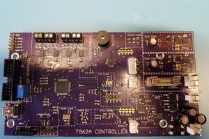
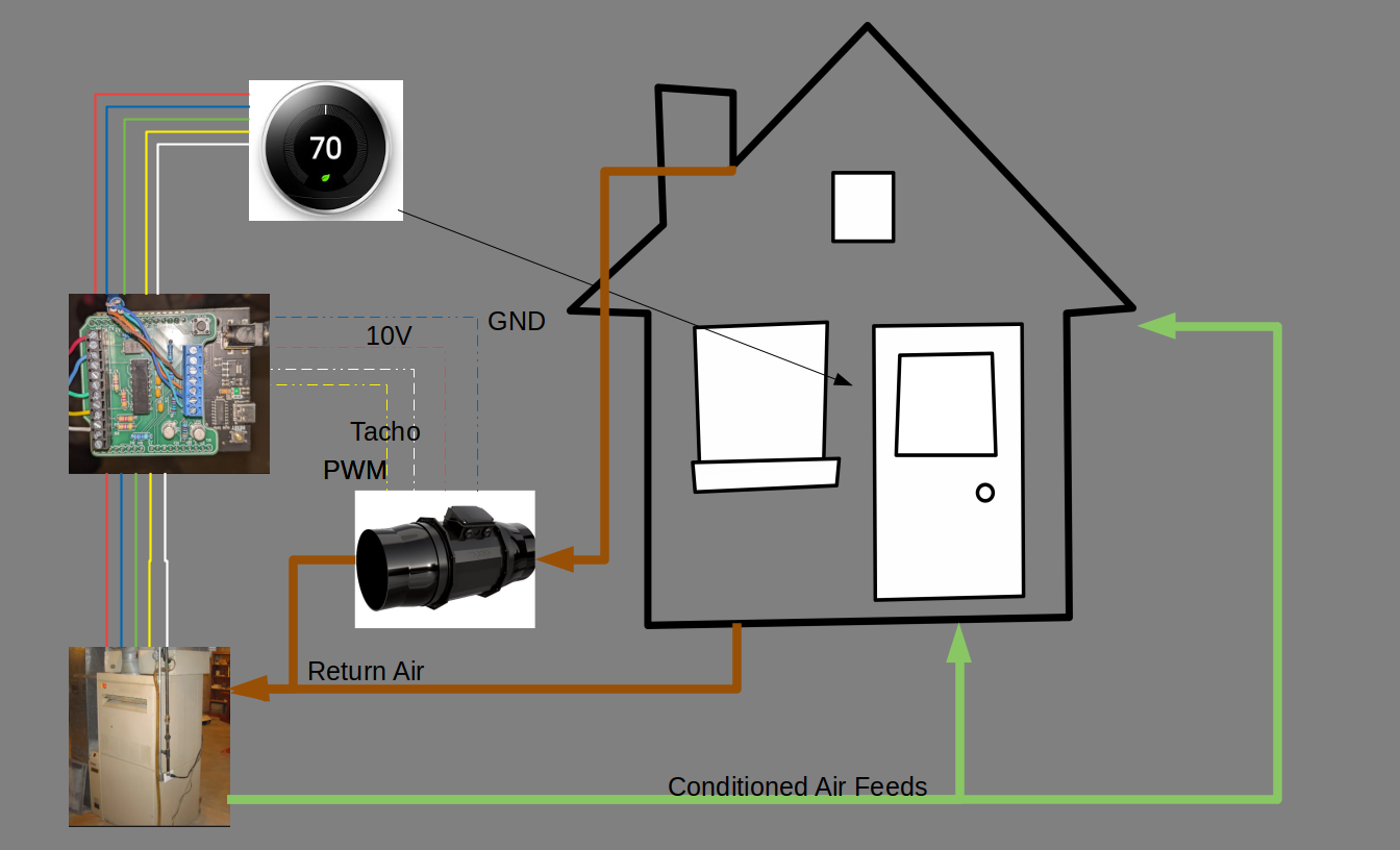
Thank you for your feedback @Bharbour. I need to put together some sort of full system diagram together if I'm going to solicit help.
I'll clarify something on the fan circuits. I am attempting to control two fans actually.
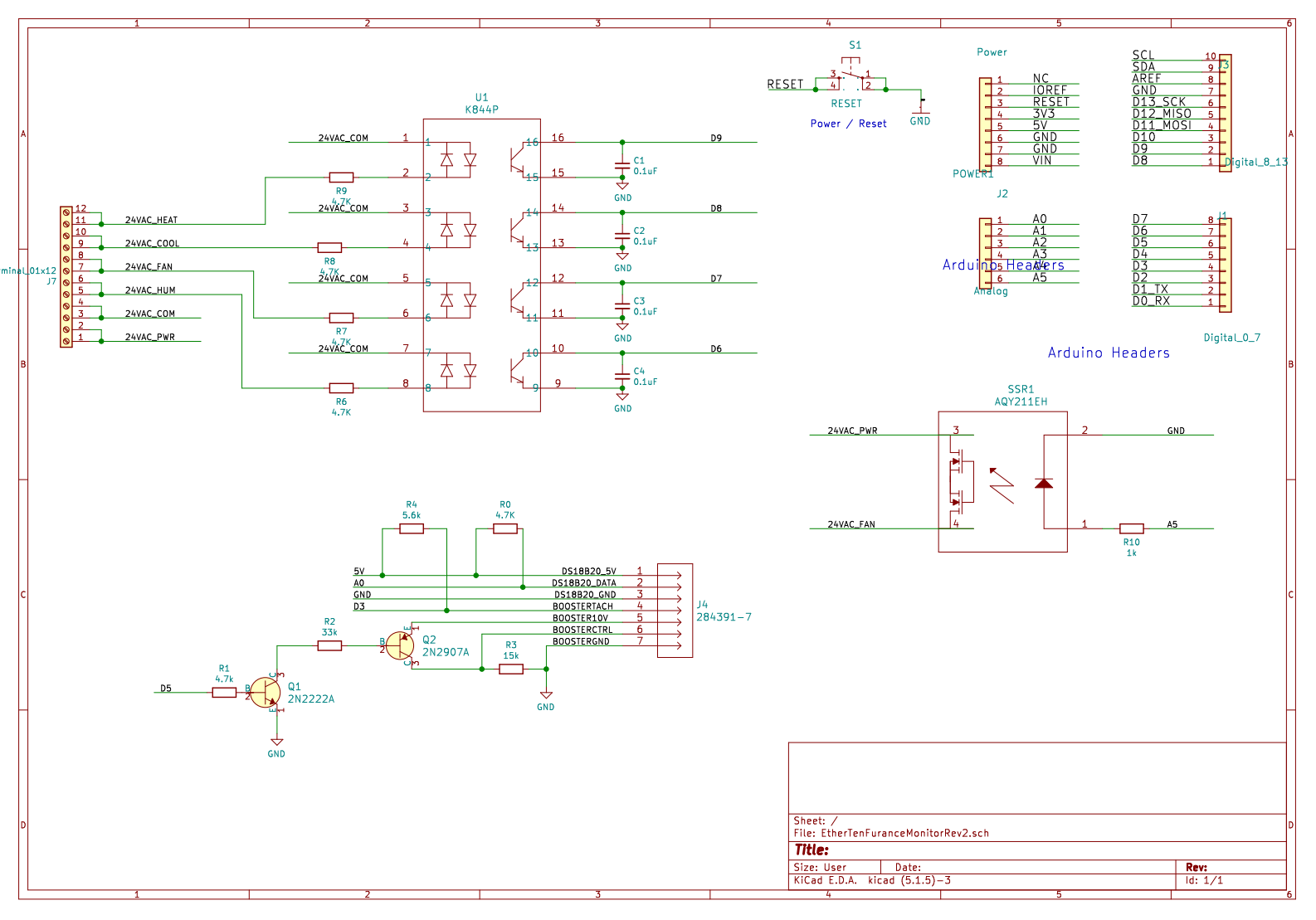
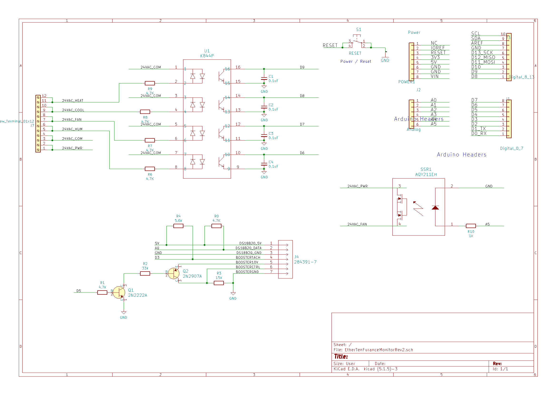
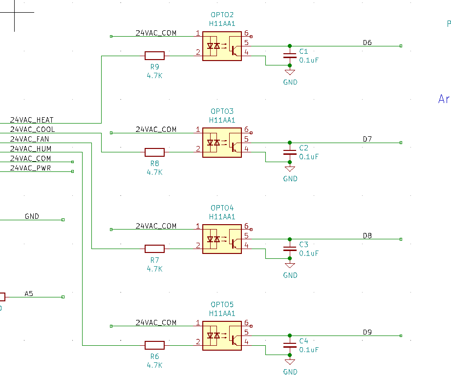
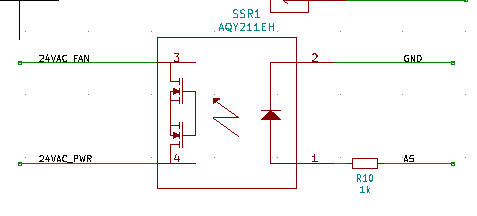
There's the main furnace fan circuit which I would in most cases, treat as read only. That is 24VAC, simple relay logic. I am using the 24VAC common to see if the Heat / Cool / Fan lines are hot. If there's a temp differential detected I want to resolve when there is no call for conditioning, I need override the thermostat to force the furnace fan on. To do this I connect the 24VAC hot to the fan line Fan. This is using the AQY211EH and is simple on off, no pulsing. Not yet tested. It's actually a lower priority item to be totally honest.
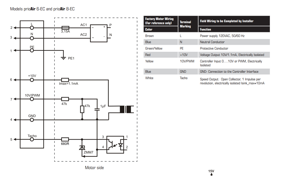
The 10V circuit is entirely separate, and yes,I'm feeding that from the 10V power coming from the fan and keeping them separate from the control board with the optos. Definitely goofed the tach input.
In reference to your other comment from the hack chat, the internal pullups I think are in the order of 20k and the signal looked stable using one of those simple pocket oscilloscopes. The signal doesn't require any conditioning and works as a nice digital as desired.