At the moment it is working as expected with no issues but with a reduction in functionality vs what was originally intended. The temperature monitoring is not implemented or hooked up. Also the SSR used to trigger the furnace fan is not being used. Fundamentally, the problem is solved but I'd like to take it a step further.
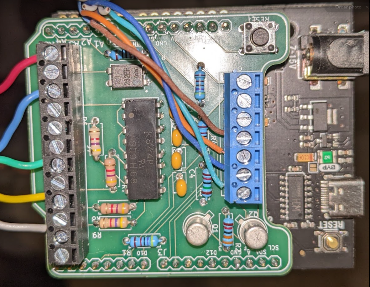
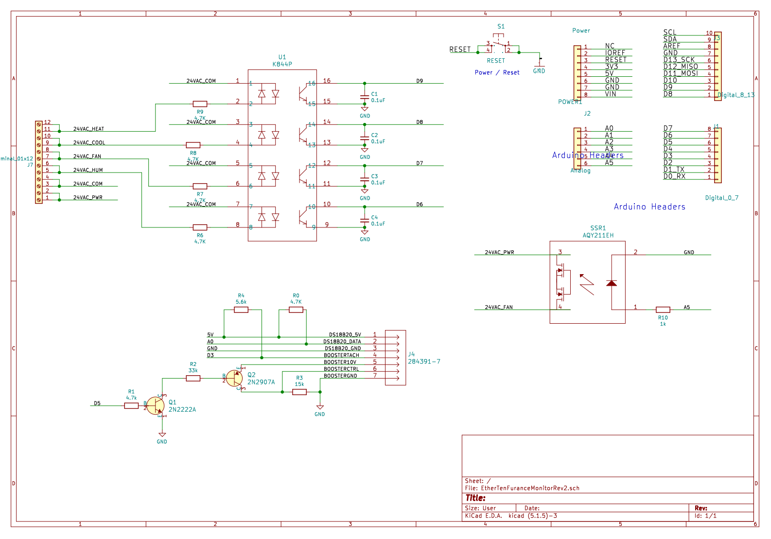
Optos were replaced with a K844P quad opto. With the extra board space I reduced the complexity of the installation by having this device simply sit between the thermostat and the furnace. Adjacent to each connected screw terminal on the left side in the picture is a terminal connected via a direct trace. This prevents having to jam multiple wires into a single screw terminal. Just makes it clean and easy.
Based on the arduino serial print, the boost fan speed is being ready correctly. I've got the board running on a sparkx arduino clone but will move to a FreeTronics EtherTen shortly once I have a place to monitor the data.
On a breadboard on my basement finally is a working revision of this. I had spun so many boards and wasted so many components i went back to basics.... I realize that an early schematic i made and had working must have been a stroke of luck because i never recreated the control and measurement I had at that time.
I intend to do a new PCB shortly that encapsulates everything. If that works on a traditional arduino, I'm going to try it on the EtherTen from Freetronics and try to get the ethernet communication side of the code up and running again.
Major changes I made:
1. Consolidated my 4 optos into one component. Made board layout much tighter and compact.
2. I learned that since the fans onboard control circuit has its own isolation, there's little risk of issues or noise so there was no worry about hooking ground to ground between my fan controls and the 'duino. I feel the etherten might have been a little more sensitive but we will soon see.
3. Figured out that a little pull up help on the Tachometer circuit does wonders for a clean and reliable reading. I was using INPUT_PULLUP but it seems it's just a tad weak.
4. Instead of jamming my thermostat wires into a terminal block and Tee'ing off of them in an attempt to share conductors, I decided that I'm going to have my board pass the thermostat signals across it. At the moment I've doubled the moment of screw terminals and bonded the adjacent terminal to minimize the amount the ac signals traverse the PCB.
Does it work? Yeah it appears to. Did i learn stuff? Sort of. The open collector circuit on the fan i still don't 100% grasp the purpose of all the components on the fan side but i don't think that matters.
I'm using the H11AA1 for everything because... I got it to work... and then yeah i just used it in every position in every iteration. I told myself this was good because "it reduces part count". I'm ordering 10, not 10 million but I was just lazy. Time to for baby bird to leave the nest and find some new components.
I've attached a link to my current schematic here which I've also uploaded to the project.
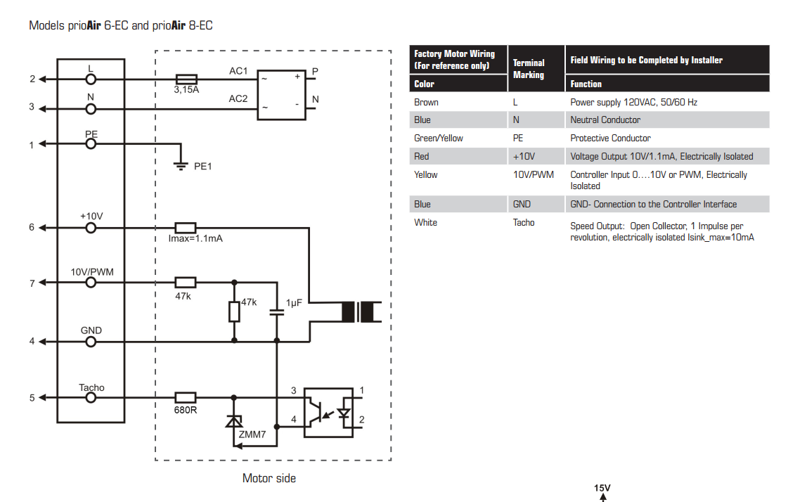
Additionally here is the interface schematic for the fan.
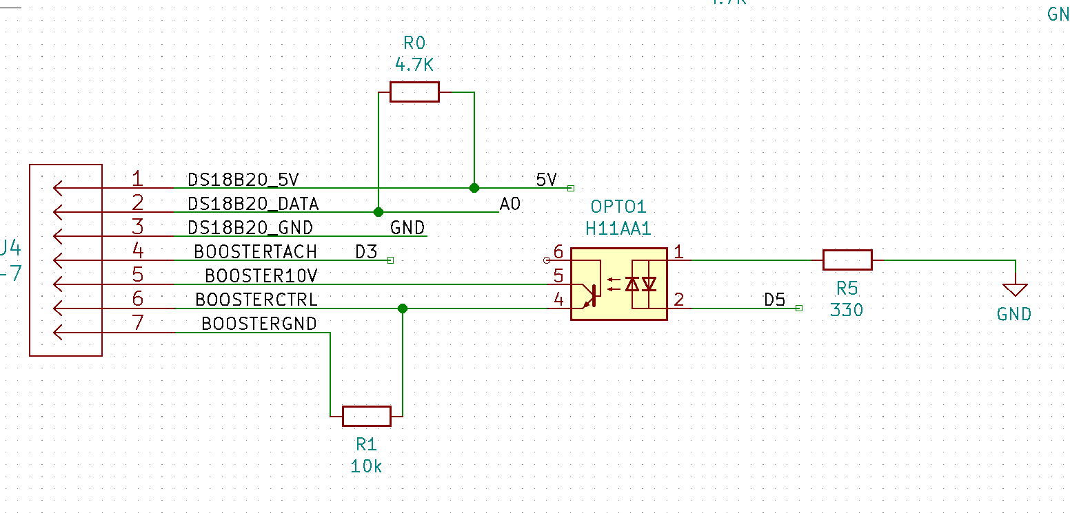
Here is how I interface to it on the board:
I am using the H11AA1 optoisolator on the 24VAC lines and also using another one (out of convenience) to drive the PWM signal for the 10v fan control line. The schematic does not show an optoisolator on the tach feedback circuit and I believe I need to add one as once this connection is made, the board stops working. Looking at my old test boards, I realized that the grounds were tied together between the fan and the Arduino. Attempting that now seems to lock the board up and it seems more straightforward to add more isolation. Not sure how it worked last time. Perhaps I just got lucky.
I have been using the same part number as I use for the AC lines out of convenience but should swap this to a DC component. Additionally to conserve board space, I'd like to get select a multi-channel component for this. Still through hole because I'm not set up or skilled enough for surface mount.
So that's Goal #1 for the next revision: Fully isolate fan circuit with proper dual channel DC optoisolator component.
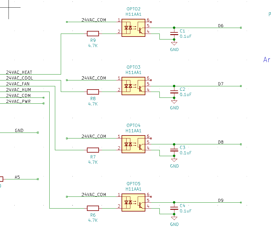
Here is an clip of the thermostat monitoring section of the board: This is working as expected, however after moving to the EtherTen board and using Freetronics Protoboard Short as a footprint template, it would be much more convenient to be able to get these condensed into a single component. Additionally, I don't think I actually need the 4th circuit monitored but given that some thermostats have different levels of heat and cool for multi-stage systems, it would be convenient to be able to do that. Also, I don't think I'll be able to find a Tri-Channel vs a Quad-Channel so no reason to remove it at this point. Difficulty in this is finding a suitable product as my background in these things is pretty weak.
So there's goal #2 for the next revision: Use a 4 channel optoisolator to handle the thermostat signals to reduce board space.
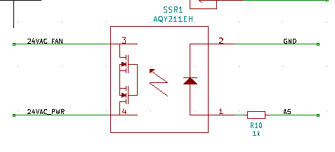
Here is a snippet over the fan override circuit. I have yet to test this but will do so prior to the next board being ordered. It would be convenient to find out if it doesn't work ahead of time, no? Anyone reading this that can tell me why this would not be able to safely switch 24VAC, I would appreciate feedback. The EtherTen board I'm connecting this to has some issues pulling this off with the shield connected but works fine running the code without anything attached. I think the most glaring issue is the motor interface circuit at the moment. Additionally I have not used the temp sensor circuits at all. so that is not a factor yet.
Any help / wisdom / "WTF.. that is stupid" / guidance is appreciated. I have thick skin, go nuts.
 On a breadboard on my basement finally is a working revision of this. I had spun so many boards and wasted so many components i went back to basics....
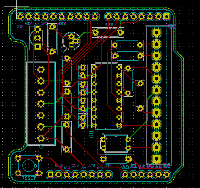
 Here is how I interface to it on the board: