-
"Flex" PCB and unusual motor
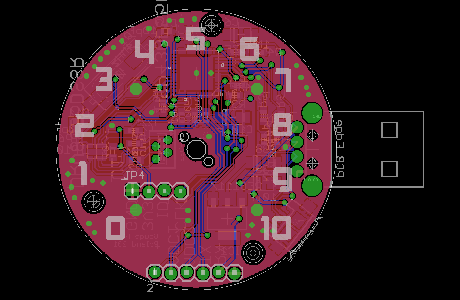
02/04/2015 at 09:04 • 2 commentsI just added a photo of simple and small PCBs which will act as a connector between the main PCB (main board sounds cooler) and the motor. As I stated earlier (or maybe I forgot) there are special (geared?) stepper motors for driving such things as tachometers, or other gauges in automotive industry. Just type "switec" in Google images and you'll get the idea. The problem is, that they are relatively expensive (few $) and relatively big. So my idea was to use those tiny motors you'll find on my photos, which I've got from China. I have no Idea what was their original purpose, but they suits me pretty well. This is a hack you might say, but well, we are on "hackaday" right?
To the point - I'll try to connect the motor and the PCB using another, tiny PCB (0.3mm == 12mils thick). Main board has a special slot (chink, crack? what is the proper word?). And the tiny ones, at one side have holes, like THT ones which will suit for the motor terminals, and the other side they will slide into the hole on the main board and the pads will be soldered together. I've seen such connections on few boards in the past, so hopefully I'll get nice working and nice looking results.
-
Still alive
02/01/2015 at 20:12 • 0 commentsCertainly still alive, because it is my most polished project to date. Recently Rev 4 boards arrived from China, and they look great. In the meantime I am working on the oven, so I could bake some bigger quantities on my own (my aim, and big dream is for 100 pcs of this, but this will depend on the interest from the public - I didn't made a webpage though. Ha ha BTW my initial plan and New Years resolution was to sell ONE to somebody). So for now, the oven is slowing me down (to little power).
-
Stepper motor non-linearity
11/30/2014 at 22:49 • 0 commentsHere's the plot showing angle change over time. I put sin on the one winding and cos on the other, and motor spins as expected, but also a little trembling is noticeable. It is as if on every step needle slowed down a little bit. The effect is, that the movement is not smooth as I like it to be. I tried to modify my sin and cos tables, but with no luck. So I used some rotary encoder and measured the angle over time in hope that this information will allow me to somehow modify my arrays and correct the error (this non-linearity is caused by the shape of the rotor and stator I believe).
![]()
-
Oscillator fail
11/05/2014 at 10:22 • 0 commentsAlthough firmware has proven to be fairly reliable i.e. it successfully communicated with the host, it worked properly only when run on the MSP430F5529 evaluation-kit. When uploaded to the target device (depicted somewhere on the photo on the far left) it would not make the device to enumerate, and there is no sign of an USB communication whatsoever (other than that, the firmware runs). The whole pull-up resistor thing that I described earlier didn't help, so after debugging further I discovered fatal mistake I made : I mixed up the XT1 and XT2 oscillator inputs :( So for now I have board which would feed RTC with 4MHz signal (if I only used the RTC), and has main oscillator without a crystal. Will try to feed the clock signal in "bypass-mode" directly from a generator when I only get back home.
-
D+ pull-up missing
11/03/2014 at 21:51 • 0 commentsI finally uploaded (some say "downloaded") the firmware into my device and it seems that host does not see it. I found an error on my schematic which caused this : there was no 1.5kΩ pull up resistor metween PUR pin and D+ pin. Every USB host has 15kΩ pull down resistors built in on D+ and D- rails, and when noting is connected to the port both lines are low thanks to that. On the other hand, full speed USB devices have 1.5kΩ pull up resistor on D+ line which "wins" over the host one (15k) and when connected, the D+ goes up. This information tells the host that something was connected and what speed it is. As far as I remember neither STM32's nor TIVA-C ARM µCs didn't require those external pull-ups (they must have them integrated), so it came as a surprise to me. Now it's time for some quick and dirty fix.
-
New layout
10/27/2014 at 08:49 • 0 commentsI was disappointed by the USB connector etched directly on the PCB. It turned out, that PCB must have been approx. 2.5mm thick to hold the device in it's place in the USB socket (I glued 3 layers of thin plastic which can be seen on the photos). So I decided to include "true" USB A connector after finding that they aren't so expensive.
![]()
 lukasz.iwaszkiewicz
