Kostas Lagogiannis
-
Project frozen - Back to the drawing board
08/29/2017 at 16:10 • 0 commentsHello all,
thank you for your interest in this project. I am sorry I 've failed to update you to say that I have put this on hold for a while now as I've started (and finished this time!) with new projects.
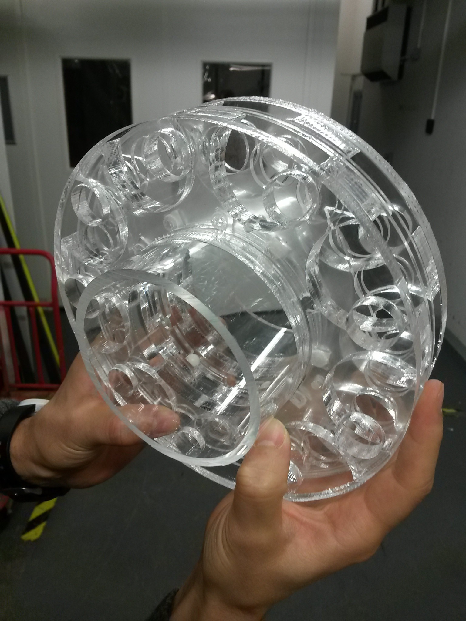
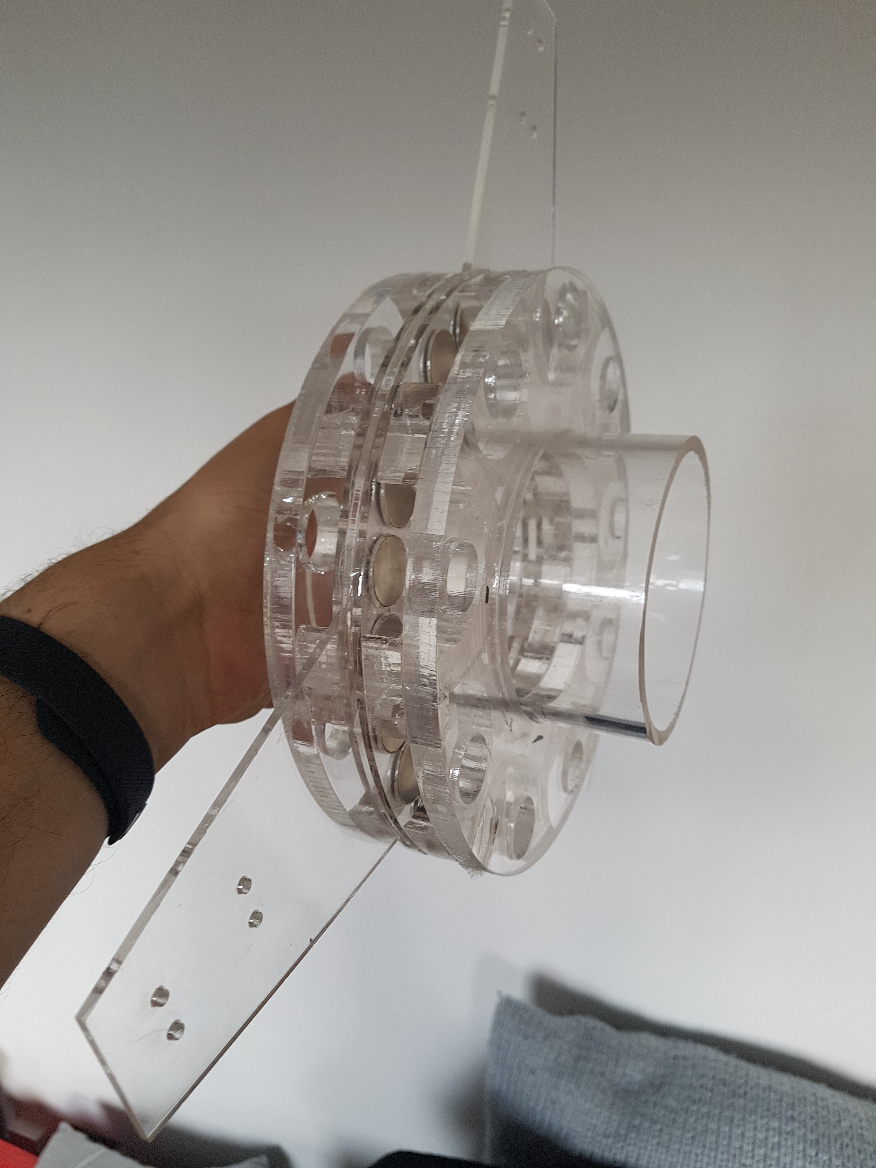
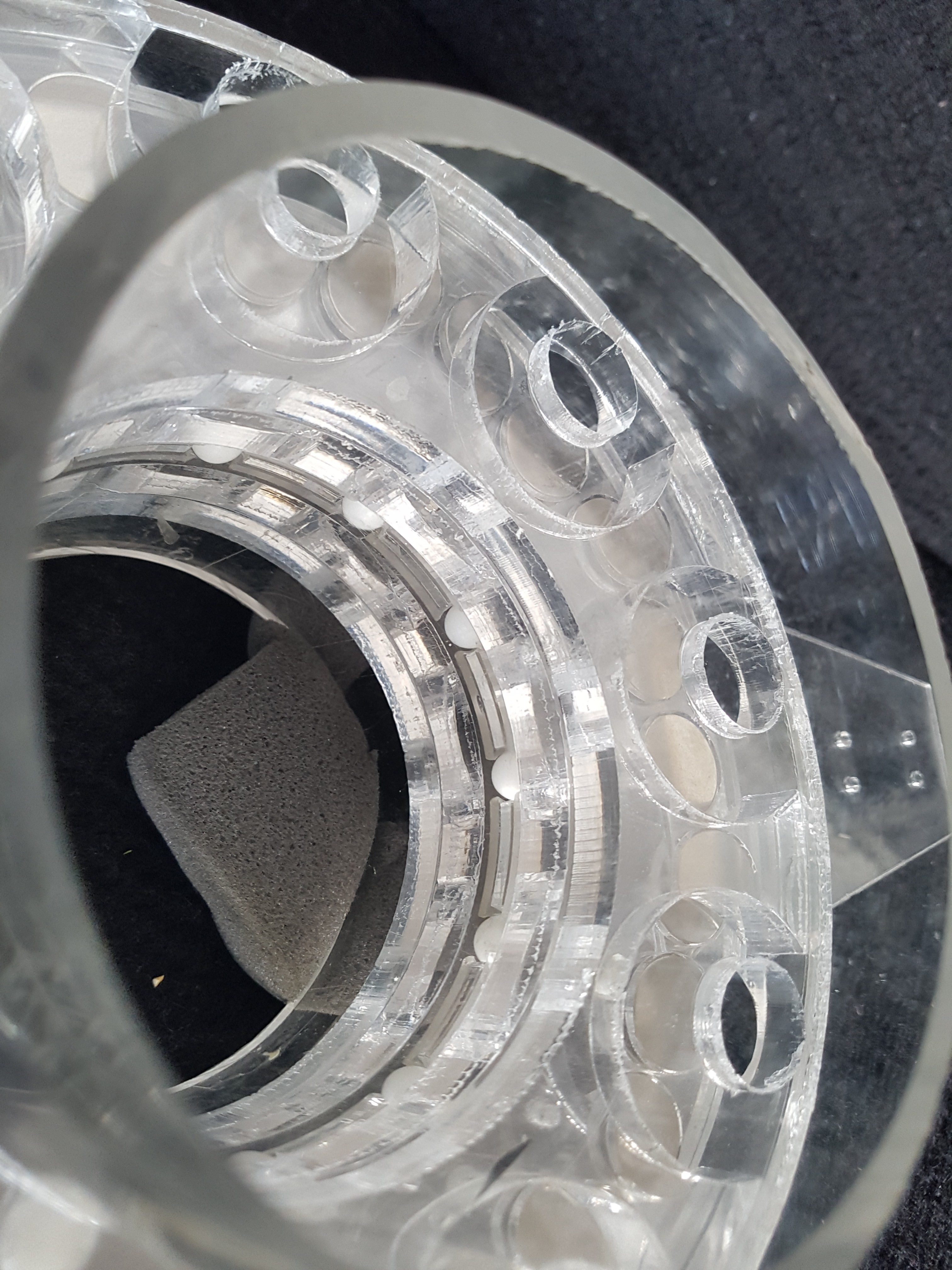
My quick update is that the custom bearing design is not adequate or comparable to what a commercial bearing could give, and also there is wobble on the rotor, unless ball bearings are added on the sides. With the current design these side facing bearings (four teflon balls on the rotor facing the stator coils) are producing too much friction if the made tight enough to stop the wobble.
I believe the ball bearing part of the design needs to be re-evaluated from the beginning, most likely consider off the self bearing solutions (Open to suggestions).
I attach a few more pictures of the a prototype (acrylic) assembly,![]()
![]()
-
free spin tested to satisfaction
10/29/2014 at 09:32 • 0 commentsTrimmed edges holding axle ball bearings, this did the trick and allow rotor to freespin. So we have modified the design accordingly.
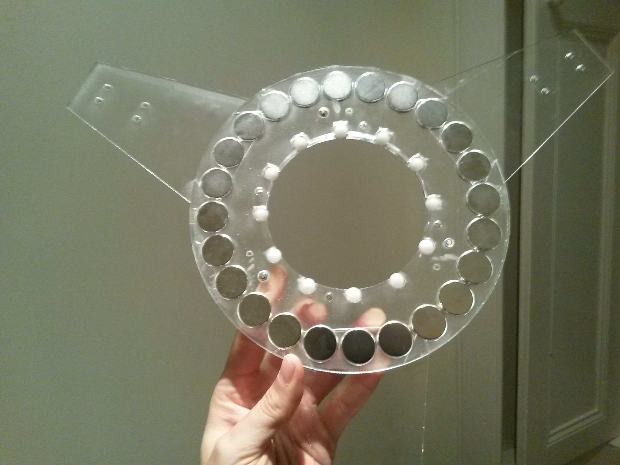
Further, the magnets where added and checked that loading does not impair spinning
![]()
Pic: most magnets added top stator liftedin this picture)
Further we added the small rotor extension wings that can be used to attach blades. Here the design needs to be modified so as to fasten these extensions more securely. Otherwise the 3 rotor laminates can be split appart by forces parallel to the axis of rotation .
![]()
(Pic of assembled rotor with magnets on both sides, ball bearings and extension wings)
-
Intented use - wind-turbine design
10/27/2014 at 13:50 • 0 commentsThe alternator design has not yet been bound any particular wind-turbine type. However, if the alternator is going to be directly driven by a wind-turbine, different types of turbines from horizontal axis (HAWT) to vertical (VAWT) and their respective variations will require various modifications to the rotor design. We've been trying to consider which design may be more appropriate using our existing construction methods. Considerations that we have taken into account is:
*the limitation of A3 sheet size, if long blades are required the turbine design should allow these to be incrementally extended to increase the turbine area.
*Laser cutting is suitable for flat material and thus designs that really depend on air-foil shape should be avoided.
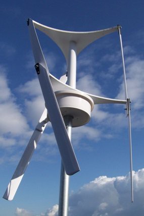
A VAWT flat blade Darius type turbine is simple when it comes to mechanisms, as the wind-turbine does not need a tail construction or to rotate to point towards the wind, further they seem to be references saying that such designs are more silent. Additionally, the turbine area can be extended in a modular design that adds sets of 3 blades vertically on the pole where the turbine is mounted.
On the other hand they seem to heavily depend on air-foil blade shape in order to generate torque, or even begin to rotate for that matter.
![]() The picture from a Darius flat-blade turbine designed by Chad Maglaque called the Jellyfish. Such a design could allow a modular expansion of the turbine.
The picture from a Darius flat-blade turbine designed by Chad Maglaque called the Jellyfish. Such a design could allow a modular expansion of the turbine. -
fastening rotor and test free-spin
10/24/2014 at 00:58 • 0 commentswent to my local hacklab tonight to drill new tapered holes to join the three rotor plates and check the rotor friction against free spinnininh by hand. These can be welded by acrylic cement but for the prototype I need to be able to disassemble.
After some slow drillling I got 3 spaced around the rotor nut/bolts through to hold them together. I then grinded the end of the screw (scalded my finger as the screw got really hot!) .
The overall friction on the rotor is quite low and the gap against stator narrow to approx 1.5mm without scratching and axle fit quite tight. But the rotor doesn't quite free run when I spin it by hand.. There is friction that seems to come from the bearings, perhaps because some of the balls don't roll. I need to check this and perhaps file the ball cages a bit.
So for now, I need to troubleahoot the ball bearings. The design seems right but due to the limitations of laser cutting perhaps some of the balls are locked when I tightened the rotor plates together. Once solved, Then we move on to adding the magnets and coils.
-
acrylic parts have been laser-cut and test-assembled
10/23/2014 at 05:33 • 0 comments1st test of using a laser cutter to manufacture the stator and rotor parts was completed with success. Made minor corrections to the design, fixing the outer rotor plates ball bearing diameter. There a few simple things to learn about laser cutting in the process as this was my first experience with one. Cutting 12mm on 60W laser can be done in 2 passes setting speed to speed to 2%,power 100% freq.100%., but on the 2nd pass refocus 3mm closer. Avoid engraving as it is not very accurate when going to depth and makes the process very slow.
The good news is that once the parts were cut the assembly, adding the ball-bearings and the sequence of the parts through central tube, took a couple of minutes before I could test that the prototype actually rotates easily! However, I still haven't joined the 3piece rotor sandwich so there was some friction that did not allow it to spin. The sandwich could be glued but for the prototype I am going to add 4 or 6 through screws with nuts and taper the holes. It feels great to hold what once was a few sketches on paper!
![]()
![]()
big thanks goes to to A.S. and Dylan
A plastic 400W alternator for smalll wind-turbine
A cost-effective micro-scale alternator build out of machining A3 sheets of plastic that aims to power basic human needs.

 The picture from a Darius flat-blade turbine designed by Chad Maglaque called the Jellyfish. Such a design could allow a modular expansion of the turbine.