 Jarrett
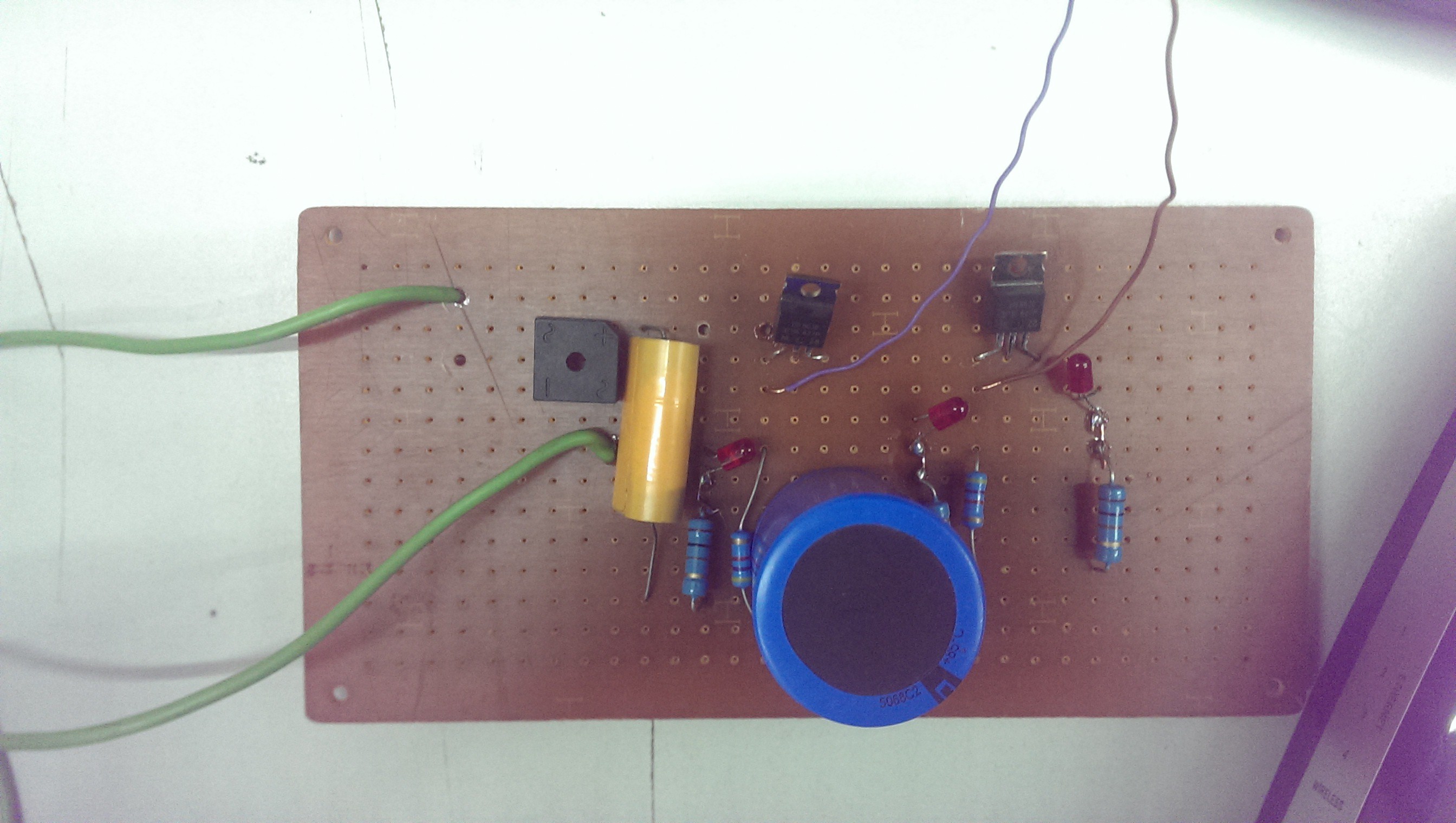
Had a couple minutes to spend on this yesterday. This is the start of the power stage. It's pretty much like in that SPICE schematic I posted below, but with components I had lying around.
The idea is to pull max 10A from the wall at 120VAC. It goes through a 2:1 transformer (just left of this frame), and then through that square-shaped bridge rectifier in the top left. After that, I get about 80VDC, and it should be about 20 amps. It gets stored in that yellow mylar cap (side-note: I think I should change it to the same value or larger than the blue aluminum cap). Energy gets stored there, and then periodically transferred to the next stage through a MOSFET. I don't remember what the MOSFETs were, but the datasheet said it could handle ~10 amps with a 25ns rise time.
Energy then gets stored in the second stage, and the electrodes are in the third stage after one more MOSFET.
The idea is that I never want to open both transistors at the same time, potentially blowing a fuse when the electrodes short out.
There's also a red "DANGER!" LED at each stage.
Now that I think about it, that transistor should be fine for the 2->3 stage, but the first one will need to be able to pass 20 amps, probably. Then I need to limit current to 20A when cap 2 is depleted and transistor 1 first opens up, but doesn't limit current as much when cap 2 is half-charged, for example. A clever application of an inductor might be the solution.
As you can tell, I'm just plowing on and building things for this project. Finesse is for when I've finished a version 0.1 and want to start making it not-suck.
Discussions
Become a Hackaday.io Member
Create an account to leave a comment. Already have an account? Log In.