So i can quickly reflash and diagnose the ESP8266's I made a simple adapter from a 2x4 IDC/ribbon plus a USB to UART adapter that i had lying around.

The pin sticking out the side is for grounding for GPIO0 to reflash it , or reset, super basic. Just needs 3V3, GND TXD/RXD

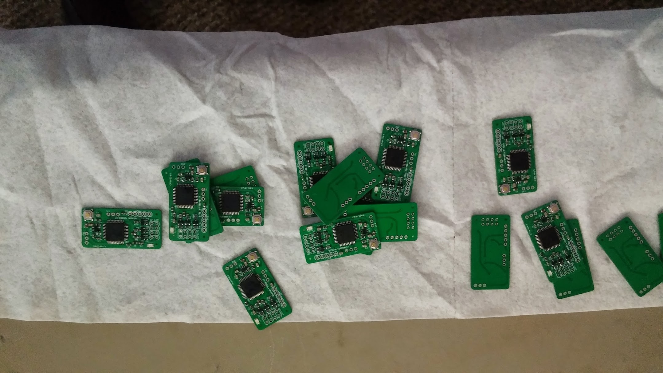
krs built all the rest of the boards, i'd put the chips on so i could flash them , the PSOC's need no supporting hardware to be flashed.
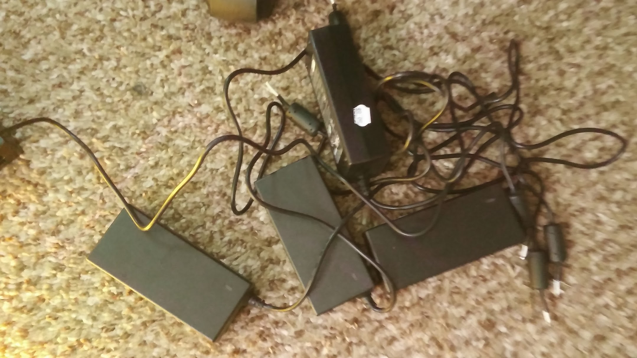
i have a bunch of PSU's from all electronics, $9 each. I have a large 5V power supply to power everything, but haven't put the base cabling in yet, so these are my cheat's and they've been working on a test load for about a month.

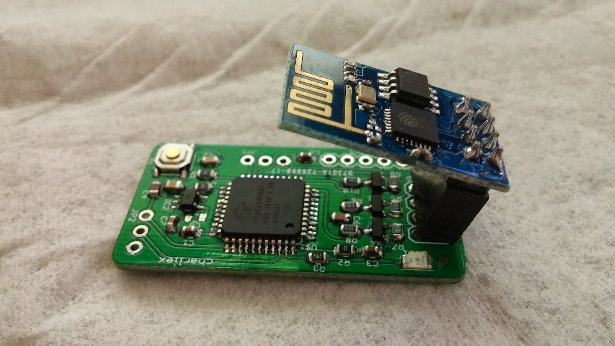
I mounted it at a slight offset, i did rotate this board design so the esp8266 adapter points away from the board, but range has been fine with this setup and it meant i can fit them into those small pots, i was going to do the usual PVC pipe plus endcaps, but i wanted to see the led's and the boards.
 Also from all electronics i had a bunch of these containers for holding SMD parts etc. I used the hot melt gun to seal off the ingress.

Side ingress was neater, but i realised it was easier to take them out for any reflashing or so on , i haven't finished the OTA PSOC reflash yet.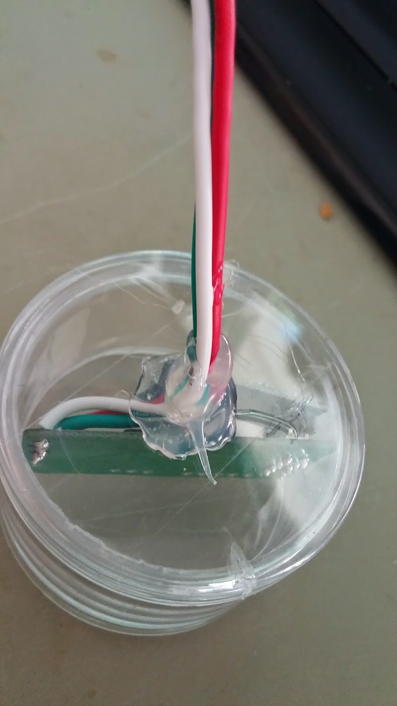
Started to get them all assembled. About half of them done.

GUI
 charliex
Discussions
Become a Hackaday.io Member
Create an account to leave a comment. Already have an account? Log In.