 Ross Bochnek
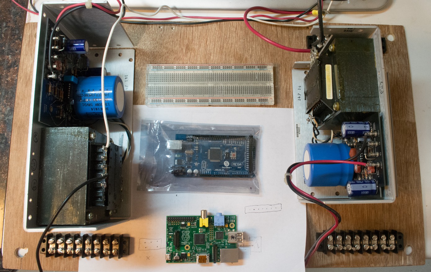
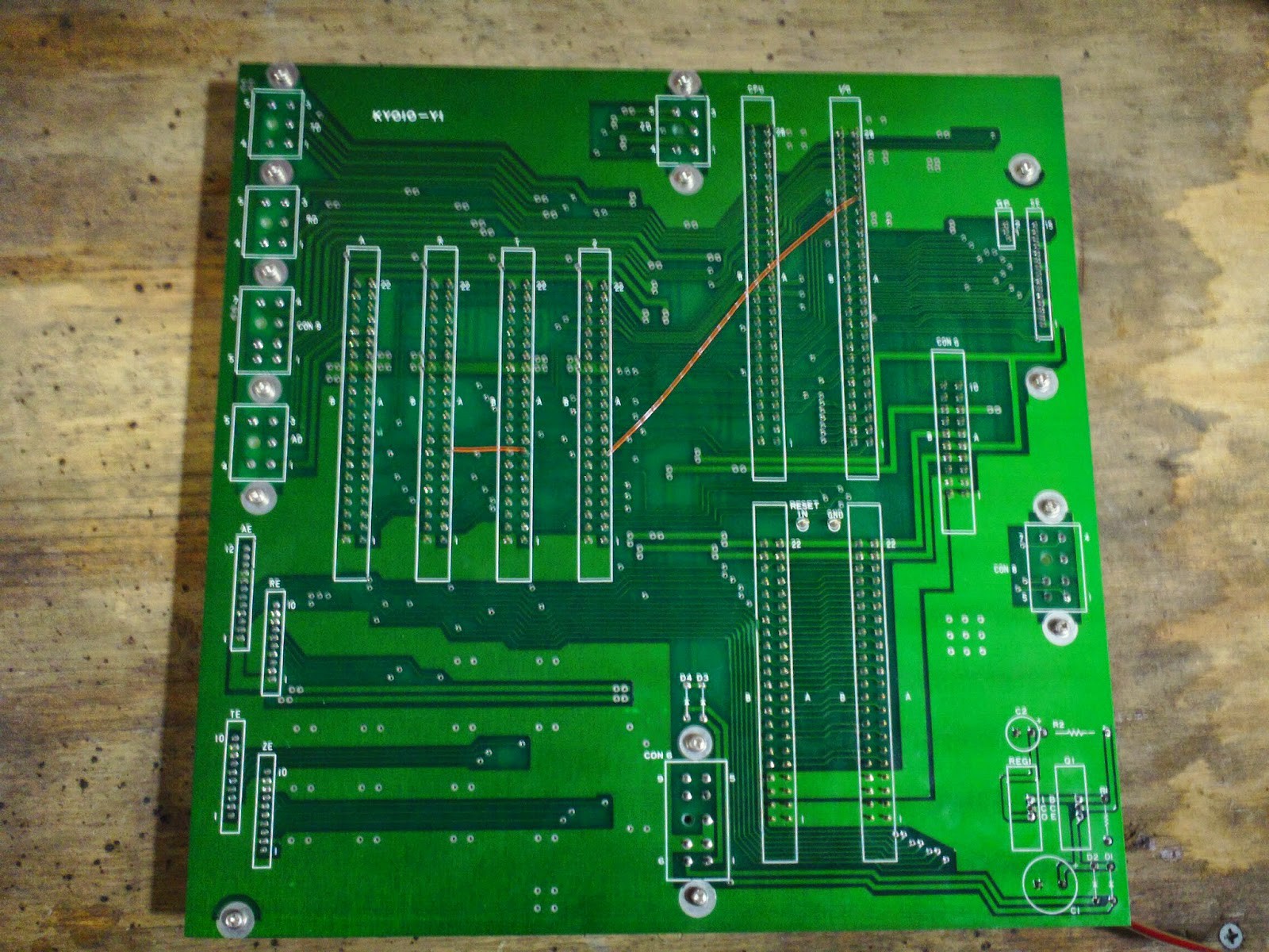
Orignal Motherboard Connector Pinout
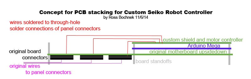
Motherboard Hack Stack
Arduino-based replacement Controller for 4-axis 1983 Industrial Seiko Robot
Already have an account? Log in.
To make the experience fit your profile, pick a username and tell us what interests you.
Orignal Motherboard Connector Pinout
Motherboard Hack Stack
We're more or less satisfied with the oscilloscope readings taken off the A Axis Optical Tachometer. We blew an IR LED, but replaced it from an old remote we had lying around. All the motors have the same manufacturer, and the main 3 axis motors have Optical Encoders rather than the Optical Tachometer we tested with on the A Axis motor (end effector motor). So, we have a good starting point for the pinout and wire colors of the encoders, and know how to power up the IR LEDs with the proper resistor.
We'll be using a Teensy 3.0 for all servo control, including reading Optical Encoders and messaging our Motor Controller board. Since we're using interrrupts to read the encoder data, we need the external motor controller. We can't Bit Bang the PWM channels to control the motors, since that method affects Arduino interrupt pin timings.
We are going to use an industrial enclosure that housed Programmable Logic Controller (PLC) Power Supply Units (PSU), relays, and electrical bus strips. I've been calling this enclosure the PLC Case. After removing most of the components, I found that I had to remove a metal panel in order to unbolt the rest of the components. So, I removed the panel from the case, will finish removing components, and we'll decide if we want to continue with a metal panel that has to be drilled and bolted to, and if so, do we want to hinge it it so we can access it more easily. Or, we may want to replace the metal panel with a plastic or wood panel.
---
11/26/14
"We're very close to finishing our Power task list. Let's choose a panel material to mount most of our controller internal onto- stick with steel or switch to plastic, wood, etc. We can reassign power bus strips for 120 VAC, 24 VDC, 24 VDC, 5 VDC, and since we'll eventually have a computer PSU, +12 VDC, -12 VDC, and maybe tap the 5 VDC from it too. We'll wire up our fuse bay, and figure out what we'll use for switches until we put the panel back into the enclosure that currently houses the toggle switches. We may want to install a power strip with breaker onto the panel, so we can get 5 VDC from a small adapter while working, and have the ability to plug in other PSUs to it as we work. We may even want to keep the powerstrip for when we reassemble the enclosure.
...
A revised, multitask plan might look something like this:
10/11/14
Our robot was originally purchased by Bell Laboratories in 1983 to test electrical connections within a clean room. Makers Alliance got it through Case Western Reserve University, but we are still researching is it went somewhere between Bell Labs and CWRU.
---
11/5/14
Aaron Humphreys posted: " I believe that I may have uncovered one of the past uses for our seiko. Pretty cool stuff. We might be able to get some documentation from the authors. Forgive the massive link.https://www.google.com/url?sa=t&source=web&rct=j&ei=KQhaVOqCNJKmyATmiIKwCQ&url=http://utwired.engr.utexas.edu/lff/symposium/proceedingsArchive/pubs/Manuscripts/1995/1995-30-Mathewson.pdf&ved=0CBwQFjAA&usg=AFQjCNF0V3WKqfYCDuhcj-uIkFo6BnAn-w&sig2=pZEv8xN11hnwoYu1jOsjAA "
11/5/14
With Aaron, we tried to trace the controller cables. I documented the wirewrap job that had been done, probably at Case, as well as the connectors. Then I removed the offending innards and placed them aside, including an obsolete sort of motherboard. Now, we can make our own masterboard to connect the cables that run to/from the robot arm to its new brain and servo controllers. We also plan to cram this all, plus a PSU and a PC motherboard into the existing controller case.
...
I'm calling our new connector board a Masterboard to differentiate it from the PC Motherboard or SBC we're going to also put in that enclosure. Do you think we should identify and shop for the connectors that are on the old connector board, or should we just hot air rework them off the original board to put on the Masterboard? I'd like the Masterboard to have connectors on one or two edges to 1/10"-center IDE ribbon cables or jumper wires, and then most of it, initially could be a huge breadboard. Then, we could replace the breadboard with either a PCB or perfboard that accepts the ribbon cables or jumpers. I can think of a similar way to do it that I won't try to describe here, since I'm sure you'll think of variations. How do you think we should do this kind of wiring so we can both prototype and then move to something more permanent?
---
Old Motherboard:
11/11/14
I've traced out all of the connectors on the original motherboard, and plan to create a schematic.
I also found a diagram of the robot's sensors; mostly limit switches, which improve accuracy and prevent physical damage from over travel.
Let's take a look at the power rectifier board, fuses, switches, and indicators inside the original controller case. The controller originally had 240V AC 3 phase power, and there are so many cut wires that we can either trace them or start fresh with the power. We're using a new PSU anyway.
I have an idea to put the controller inside one of our PLC cases, and mount a computer monitor on the inside of the door.
At our meetup on 11/11/14, we'll continue discussing plans for power, case, board interfacing and stacking, how we're going to protect the robot from itself electrically and physically via fuses/sensors/overcurrent protections/E stops, and what I learned about the connectors this weekend.
OEM Seiko Robot Controller Motherboard
numbers indicate how many connections to what
there were 4 servo controller boards, 1 CPU board, and 1 I/O board
Axis Z
Encoder Connector
-5 GND
-3 to own servo controller board
-2 unconnected
Driver Connector
-2 to own servo controller board
-1 to I/O board
-1 to GP
-1 unconnected
Axis T
Encoder Connector
-5 GND
-3 to own servo controller board
-2 unconnected
Driver Connector
-2 to own servo controller board
-2 to I/O board
-1 to GP
Axis R
Encoder Connector
-5 GND
-3 to own servo controller board
-1 unconnected
-1 axis R encoder connector
Driver Connector
-2 to own servo controller board
-2 to I/O board
-1 to GP
Axis A
Encoder Connector
-5 GND
-3 to own servo controller board
-1 to servo controller board Axis X
-1 unconnected
-1 axis R encoder connector
-1 to G connector
Driver Connector
-2 to own servo controller board
-2 to I/O board
-1 to GP
Other connectors
GP
-1 to each Driver Connector
-1 to Con G
-1 to Con 8
Con G [Gripper?]
-2 GND
-8 to CPU board
-8 to I/O board
-1 to Axis A Encoder Connector
-2 to each servo controller card
-1 to GP
-3 to Con 9
-unconnected
Con 6
-3 GND
-1 to a capacitor
-2 to a diode
-2 to Con G
-1 to itself
-1 to Axis A Encoder Connector
-2 to CPU board
-2 to I/O board
-1 to each servo controller board
Con 8
-5 to I/O board
-1 to GP
-1 unconnected
Con 9
-2 to each servo controller board (8 total connections: 4 individual pins to each + 1 pins to all 4)
-1 to Con 9
-2 to Con G
-1 to its own pin (that connects to all 4 servo controller boards)
Con SE
-4 GND
-8 to I/O board
-3 unconnected
=====
11/18/14
10/14/14
Dave figured out that the servo motors only need a minimum of 24VDC, and we're going to use our 30V PSU for testing. Dave has a source for controllers for the motors, and $50 will cover all 4 brushed motors. I think we'll want to control those controllers with a microcontroller, and there are lots of options.
---
10/22/14
There are at least 2 different servos in this bot. Their mutual manufacturer, Yaskawa, is still in business, and I have requested documentation from them about the servos I have identified in the bot so far. They are both brushed, totally enclosed, self-cooling, continuous, DC motors with optical encoders. Their encoders seem to vary in voltage, output waveform, and possibly pulses per revolution.
The servos are:
Minertia Motor Mini Series
UGTMEM-03MC4OE
Optcal Encoder possibly SJ type
close datasheet includes: TSE2-C249-1C.pdf
&
Minertia Motor RM Series
UGRMEM-02SDS21
with
UTOPI-08ZAH Optical Encoder at 800 pulses/revolution
close datasheet includes: TSE-C253-10C.pdf
Most data has so far been found on Yaskawa's own paper data sheets that are probably old, low quality, and have been scanned. In the late 1970's or early 80's, the Seiko robot included motors that probably came after the data sheets were created, judging by their "Design Order" letters C and D in their respective product codes. Hopefully, Yaskawa will find some more updated and higher quality data sheets to send me; even if they have to scan them for the first time.
---
11/5/14
Tonight, Dave uncovered the end effector ("A" Axis) servo...
Aaron or Dave post an image or the codes from the end-effector servo. I've had some luck finding specs on the servos based on their label codes.
---
11/8/14
http://www.ti.com.cn/general/cn/docs/lit/getliterature.tsp?genericPartNumber=sn75183&fileType=pdfThere is a wire wrapped circuit board I removed from the controller. That was one of the ends that the colorful ribbon cable was connected to, but I can't find what the other end went to. The board only has one type of IC left on it: the SN75153N. Judging by the empty IC sockets with different numbers of wired pins, it had 2 other types of ICs. I think some of the board was used to read the optical encoders of the servos. The SN75153N is a quad differential line driver, and my phone insists on pasting the datasheet link only at the top of this post. Might it have been used to read the optical encoders? I'm not yet familiar with differential line drivers.
---
Dave posted:
"
The number of wires going to the encoder will help determine what type it is.
Single Ended usually uses 4 wires. Ground, power, and 2 signal wires.
Differential usually uses 6 wires. Ground, power and 4 signal wires.
Single Ended uses the presence or absence of voltage relative to ground to indicate a high or low state.
Differential uses the relative voltage difference between 2 signal wires to indicate high or low. The wires are not tied to power or ground. They float. They are less sensitive to intereference since stray EMF will affect both wires similarly causing little or no relative voltage difference. You get a higher signal to noise ratio.
Most everything you see now days is 5V or 3.3V single ended. Occasionally 5V or 3.3V differential.
Going back a few (many) years you also see 12V, 15V, and 24V with differential being more widely used than single ended.
20ma current loop was also popular. It is differential but uses current instead of voltage to indicate a high(20ma) or low(4ma) state. You often see current loop used with one side tied to ground (not floating).
The main design advantage to current loop is that you instantly know if a wire comes loose. With digital circuits, an unconnected pin floats high. You have no direct way to tell if you are getting a constant high signal, or if the wire fell off.
DC Brushed motors will use 2 wires for power.
DC Brushless motors will use 3 or more wires for power, sometimes many more.
Stepper motors will use a minimum of 4 wires, and a max of 8 - except for 5-phase ones that...
Read more »10/12/14
All Electronics has multiple 24v power supplies, but only two 48v power supplies. Would it be possible to wire the following 48v PSU in series with one of our many 12v PSUs to supply the 60 VDC required by the robot's servos?
The robot already has an air line running to a port by the end effector, and even if the end effector was the only pneumatic device we use, the included solenoid valve should have its own 24v PSU that we switch via relay.
All PSUs, including 24v-
http://www.allelectronics.com/make-a-store/category/480/power-supplies/1.html
48v PSU- $37.75 6.3A
http://www.allelectronics.com/make-a-store/item/ps-4863/48v-6.3a-power-module-ac-dc/1.html
http://allelcdn.upshotcommerce.com//mas_assets/theme/allelectronics/spec/PS-4863.pdf
Their other 48v PSU is only rated at 0.38A
10/11/14
I have been reading the documentation for our blue Seiko industrial robot. It's different from the large yellow Fanuc industrial robot, but is from the same era.
The main thing we need to do to make it even remotely usable is to hack the power supply. Although it probably has a power supply that requires 3-phase 220-240 VAC, Seiko used to offer an alternative PSU, and everything internally seems to run on DC voltage anyway. Even without Seiko's alternative PSU, I think we could use a spare desktop computer PSU + another one or two. All the digital logic seems to use 5 VDC, and the analog circuitry requires 12 VDC; both of which the computer PSU could supply. To make the robot move, the pneumatic solenoid valves require 24 VDC, and servo motors require 60 VDC. Once we can provide 60 VDC, we can probably switch it to the servos via relays.
I'm thinking we may also want/need to hack the robot by providing our own CPU and way of programming it. There are numerous ways to do this, including an Arduino Mega with a computer running Snap or Scratch for Arduino. That way, the robot could be used to teach programming, and almost anyone could do it. We could also get quite advanced, and run Ubuntu with Robot Operating System.
I don't know how much the robot itself weighs, but it's pretty heavy. An unhacked robot can be really, really precise, so they recommend a very level mounting surface, bolting the robot to its table, and the table to the floor. I don't yet know the robot's encoder protocol, but if we can figure that out, I hope we can still have a very precise robot even after hacking it.
I'd like to show our EEs some pages in the robot's documentation, and discuss the possibility of finding power supply units and powering the Seiko up.
---
11/18/14
Next Steps:
I picked up a couple of Seiko D-TRAN RT 3000 robots. One looks to be mostly complete, the others are partial. I don't have the controller units, so getting them working will require following your approach. What motor controllers did you end up using? And can I ask, what are you using your robot for?