-
Test Board for ESP-201
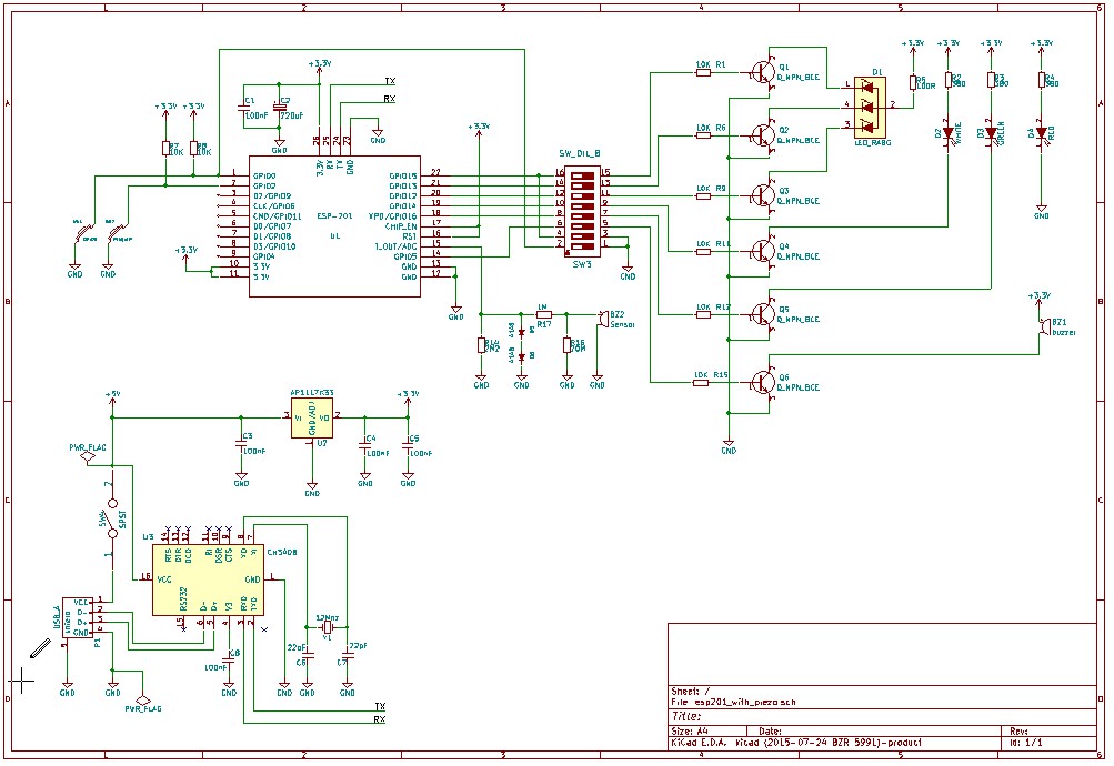
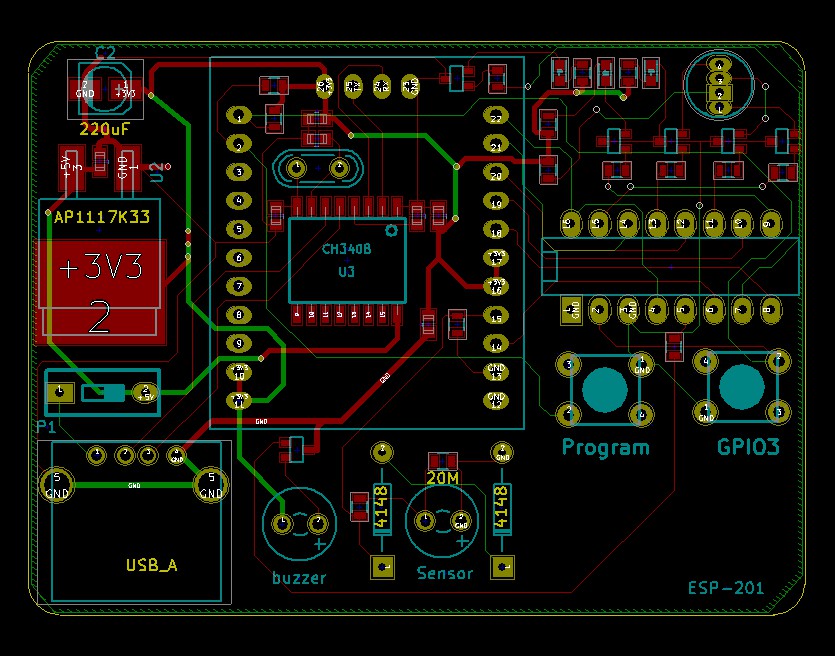
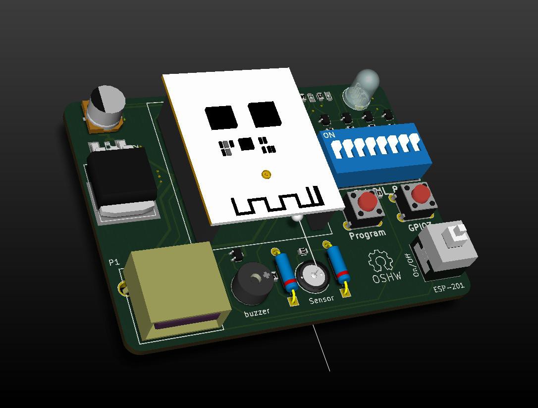
10/11/2015 at 04:10 • 2 commentsJust in case anyone wants a test board based on the little white ESP-120 Module, here's some ideas... (KiCad)

The board can be used for testing and programming the ESP-201 module... It's pretty much the same as a board I found when googling but aimed at testing inertia sensor using the ADC... All files available on request...
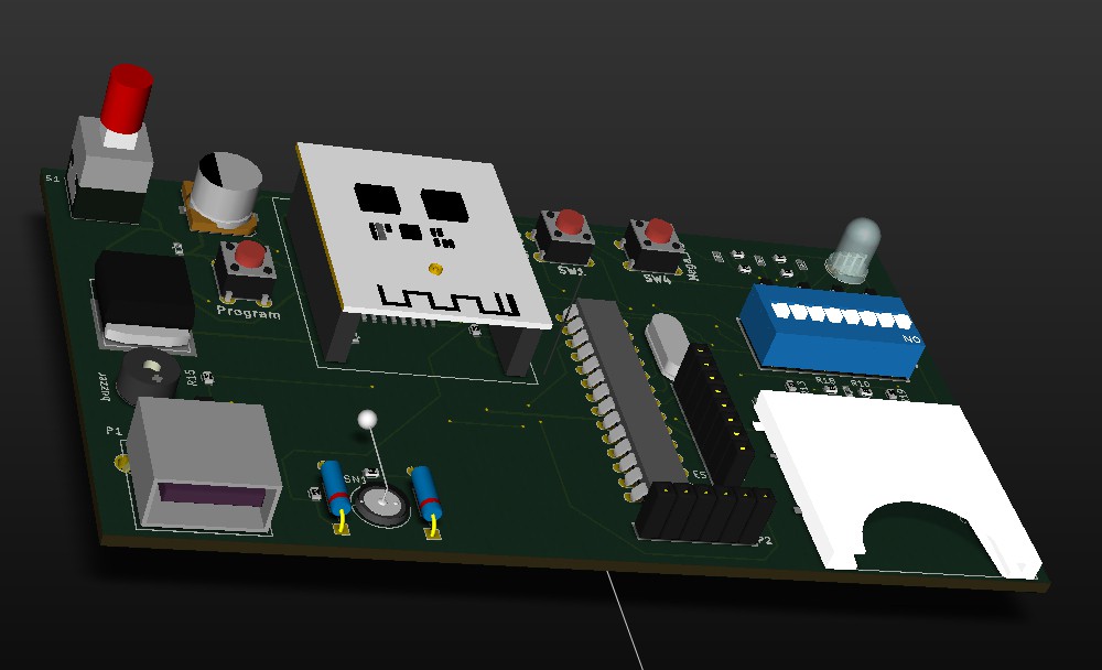
The unit is powered by USB and contains a Buzzer, RGB Led and a Piezo sensor...
The USB circuitry (CH340B) is under the ESP201 (little white board module).
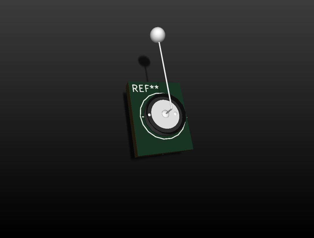
Note my design for the sensor, it's a standard inexpensive piezo disk modified to greatly enhance it's performance when used as a sensor... the design can out perform sensors costing many tens of dollars...
I managed to replaced a $34 sensor with a $2 sensor and small weight connected to a piece of wire soldered to the disk... Additionally, if the weight is resting lightly on a surface (such as a window or door frame), vibration is transmitted directly again greatly improving detection...
Updated version:
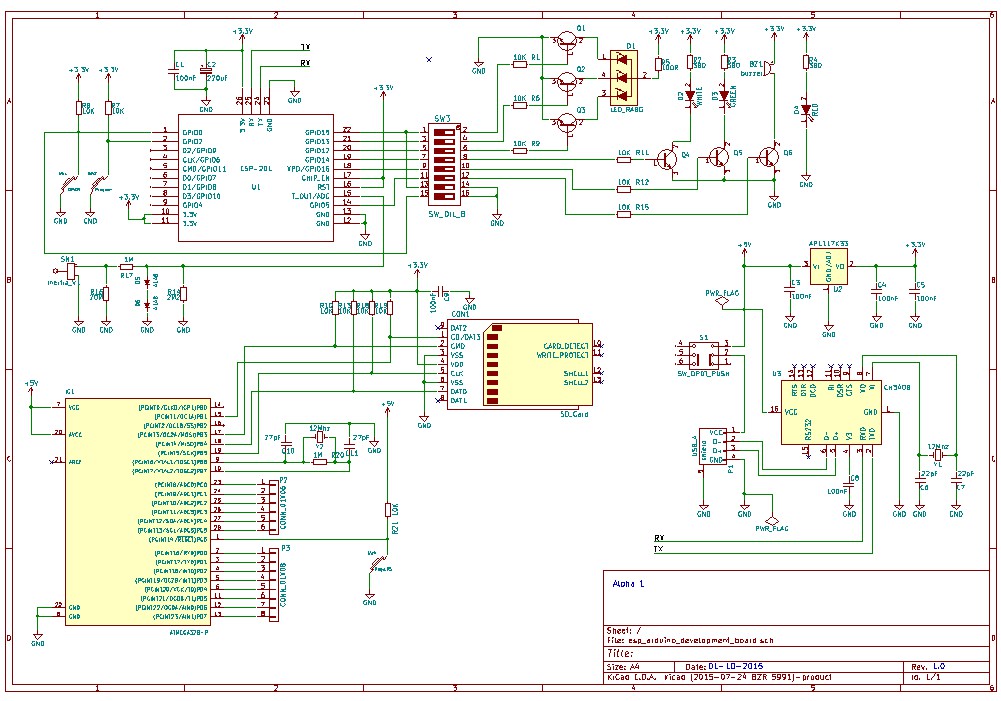
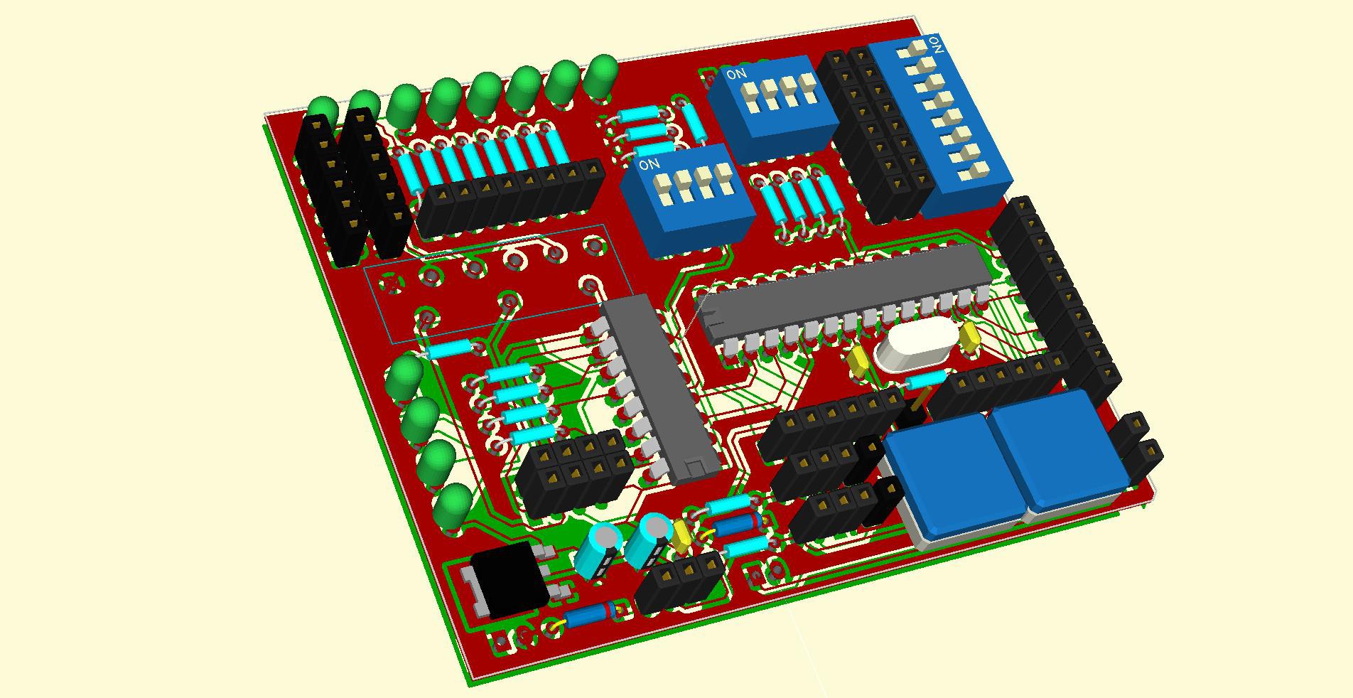
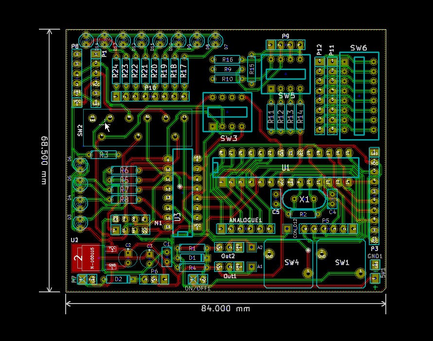
includes on-board SD reader, USB to Serial CH340B, AtMega328, Inertia sensor for AD testing etc... Will probably redo this for through-hole as it's easier to build... I've yet to test it so don't be surprised if I screw up and I have still to add the TFT for debug...
...
-
Programming ESP with Arduino IDE
04/28/2015 at 11:51 • 0 commentsLooks like you can now program the ESP series of boards directly from the Arduino IDE
This is a game changer for me (and I guess many others)... no longer do we require an intermediate processor to do our bidding... Most simple control applications can happily be accommodated by the little device on its own...Looks like there are a few positives including a faster processor too... more pros and cons later...
Of course I still need a development board, with options to handle more of the ESP board revisions but basically the circuitry is greatly simplified... I guess it's back to the drawing board...
New Criteria:
- Support ESP 01, 07 and 12 (and possibly more)...
- Display status of all GPIO's (all buffered, 9 pins available)...
- Display RX/TX status (buffered)...
- Provide support for working with the ADC (LDR or similar)...
- Capable of both Testing and Programming...
- Capable of testing several ESP models (01, 07, 12, ?)...
- A well regulated 3.3 volts @ 800mA (battery & charge circuit option)...
- Breadboard connectivity (all pins are broken out)...
- Self contained? USB? TH/SM or both?...
...
More info here... https://hackaday.io/project/5150-arduino-ide-for-esp8266-quickstart-guide
Comment:
It's been noted that I design a lot of development boards but don't appear to build them.
Rational:
In the ESP world things change very quickly. This results in me having to modify designs to accommodate these changes, besides, I don't have the cash to prototype everything I design.
Old guy on fixed income...
-
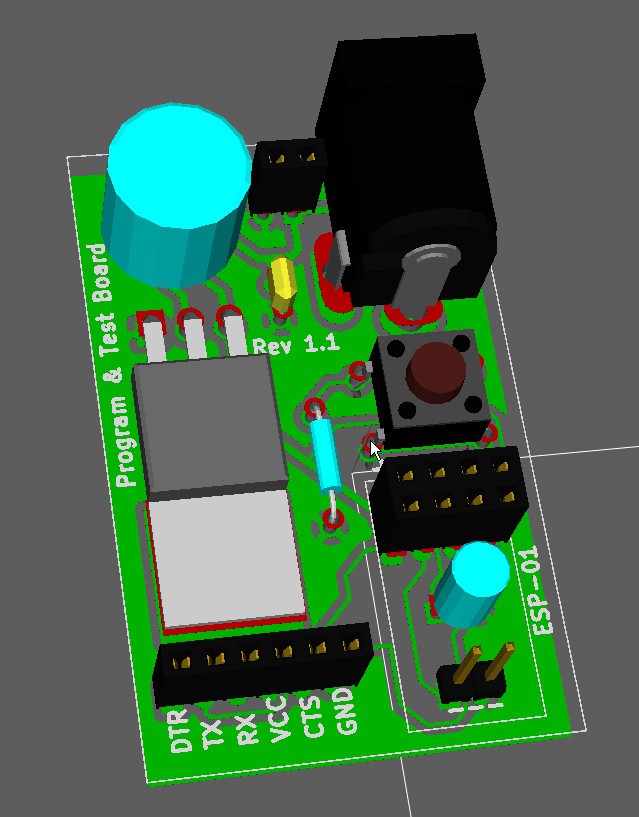
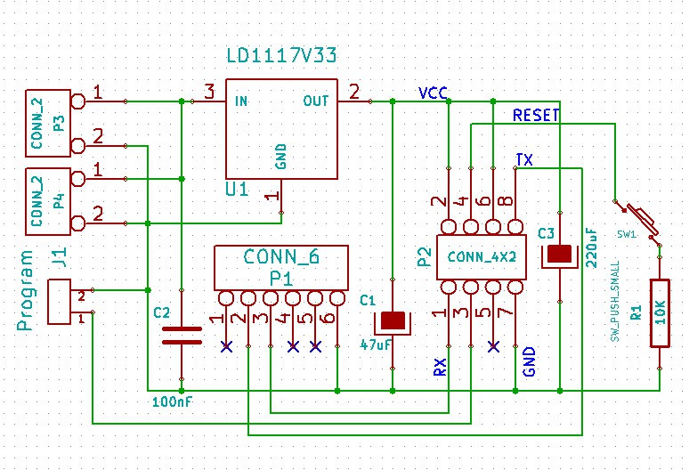
A little Program Board
03/18/2015 at 16:21 • 0 comments -
Version with ESP8266 3
12/18/2014 at 11:46 • 0 commentsNow you test ESP-01 and ESP-03
- You can solder one ESP-03 directly or create a few small breakout boards, add some header pins and plug it in, just like the standard ESP-01 version...
- Simplified the board by dropped the Leds and buttons, and changed reset switches to something a little more common...
- The ATMega should be socket mounted... (will add zif socket to final version)...
Along with this simplified version I will also complete the other design to make a more complete dev board...
If anyone spots any errors or has any comments please do not hesitate to post...
Mike
-
Going with the basics
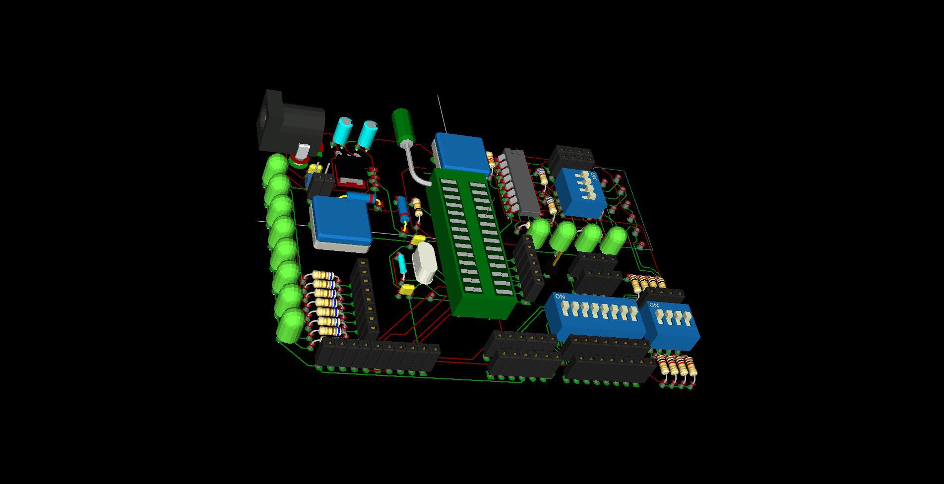
12/12/2014 at 02:29 • 0 commentsAs I have not had any requests for any additional functionality/connectivity, I will go with the original simple design. The PCB will be a through-hole version as I don't yet have all the equipment for SMD assembly.
The first test will use 902 firmware (ESP8266) and utilise the zeflo's "Weather Display" code... with some minor tweaks...
I will add all the necessary links and code...
Playing around with using ZIF for the ATMega?
12th Dec 2014
Decided to rearrange the components to make room for an inexpensive ZIF socket to allow quick changing of the 386P... Obviously you could just use a standard socket if you don't have a ZIF...
Might be a few more tweaks but will finalise the board this week end...
-
What to add to Dev Board?
11/25/2014 at 18:22 • 0 comments -
Looking for KiCad parts
11/16/2014 at 16:33 • 2 commentsI'd like to get the exact parts and images so the board image reflects reality... Can't seem to find 3D images for KiCad... any links would be appreciated....
-
Initial design (basic)
11/16/2014 at 03:40 • 0 commentsESP8266 Module
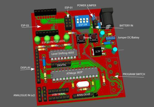
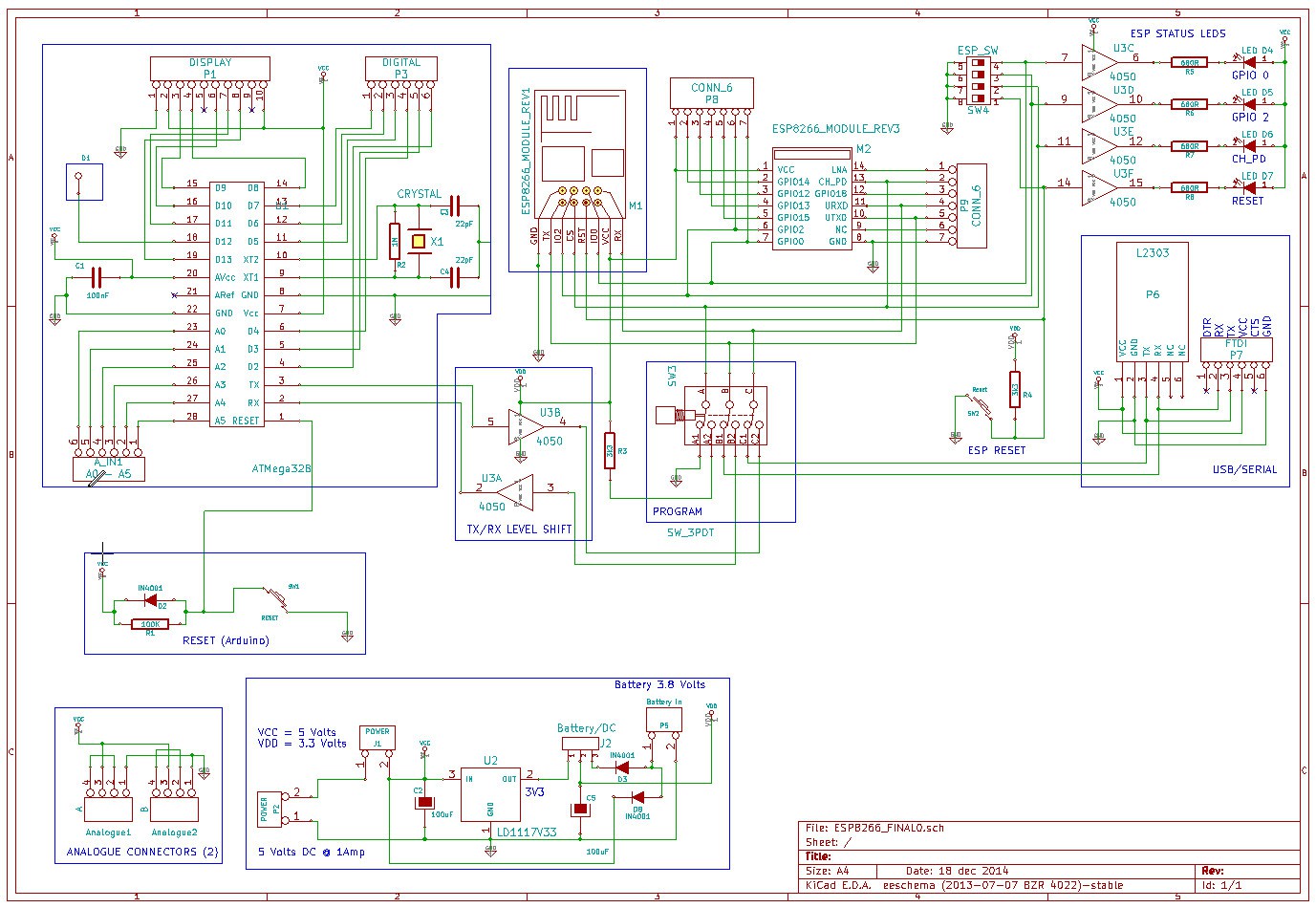
As part of the testing I want to be able to monitor the ESP8266 pins so I added a buffer and some leds to GPIO0, GPIO2, CH_PD and the reset pin... The two remaining gates on the buffer (4050 IC) are used for level shifting the RX and TX (in the event we have 5 and 3.3 volts supply)....
PowerThe board is powered from an external 7 to 12 volts power supply (optional battery header with reverse protection, so allow for ~0.6 volt drop)... The 3.3 volt regulator can handle 1.5 Amps.
Optional DisplayAdded header for the little TFT (cost $9 or less) to act as console making the board mobile. Basically anything you echo to console can be directed to the display...
Programming the ESP8266Programming the ESP is accomplished with a little L2303 USB to Serial board and controlled by two switches... A better method might be a 4 pole changeover relay or a single switch if I can find one in KiCad parts... The L2303 is very low cost at less than $2.
The on-board ATMega 328I've added two 6 pin headers, one for free Analogue pins and another for free Digital. There are also two 3 pin headers for connecting potentiometer or sensors etc...
MiscellaneousAdded 8 pin header to connect to any of the general purpose Leds (active low, with 680R current limiting resistors)... Added reset switches for on board ATMega and another for the ESP8266 reset pin (in case we need it later)...
There's a 10 pin header for an optional 1.8" colour display I use for console output and messages in sketches... It only costs $9 and makes the unit portable (if you add a battery)....
I was positive I added a schematic last night but I don't see it now and the markdown is not behaving?
ESP8266 Development PCB's
Development board for ESP8266 the make up of which can be decided by the community
 Michael O'Toole