 jorisplusplus
-
High voltage
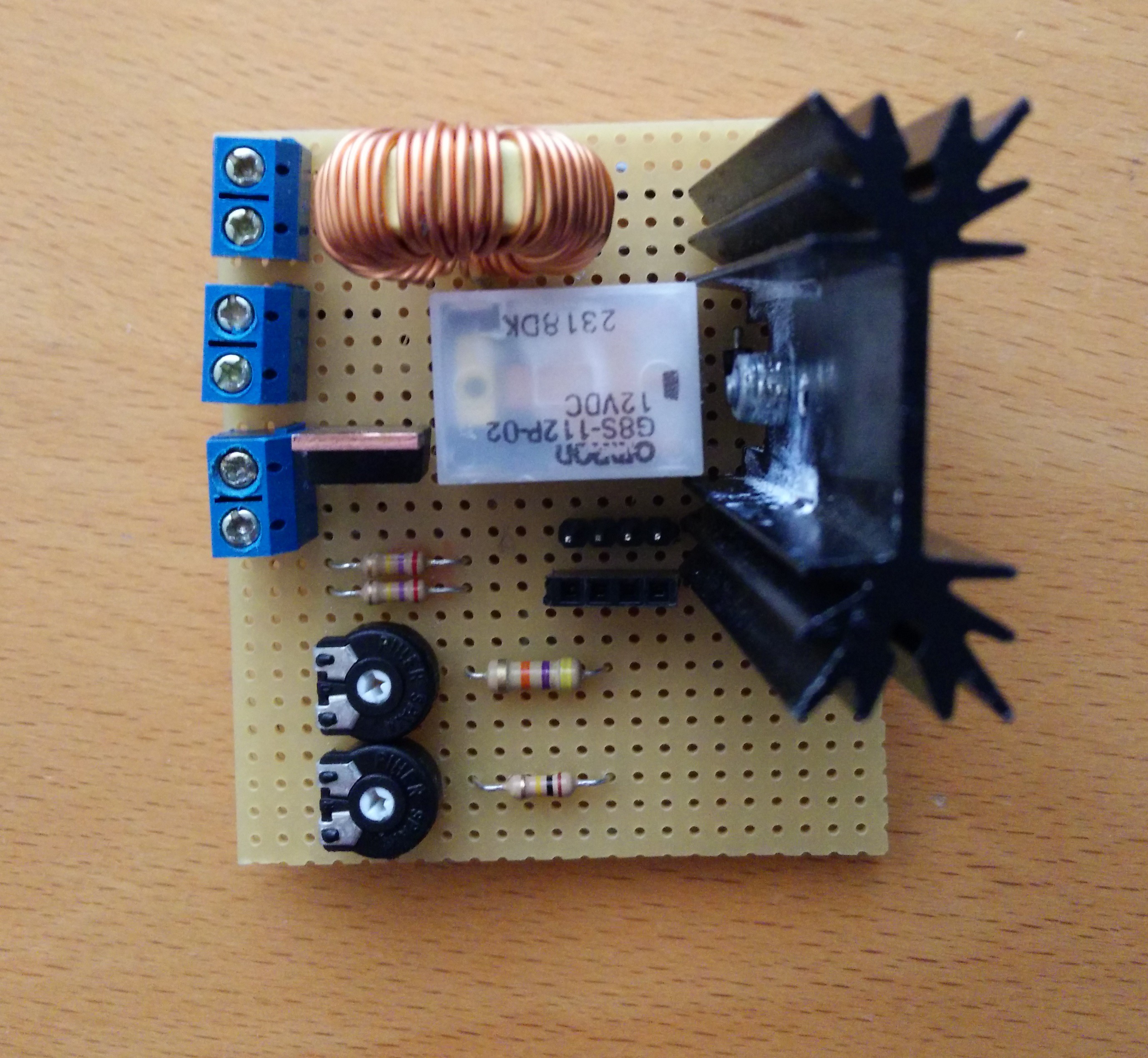
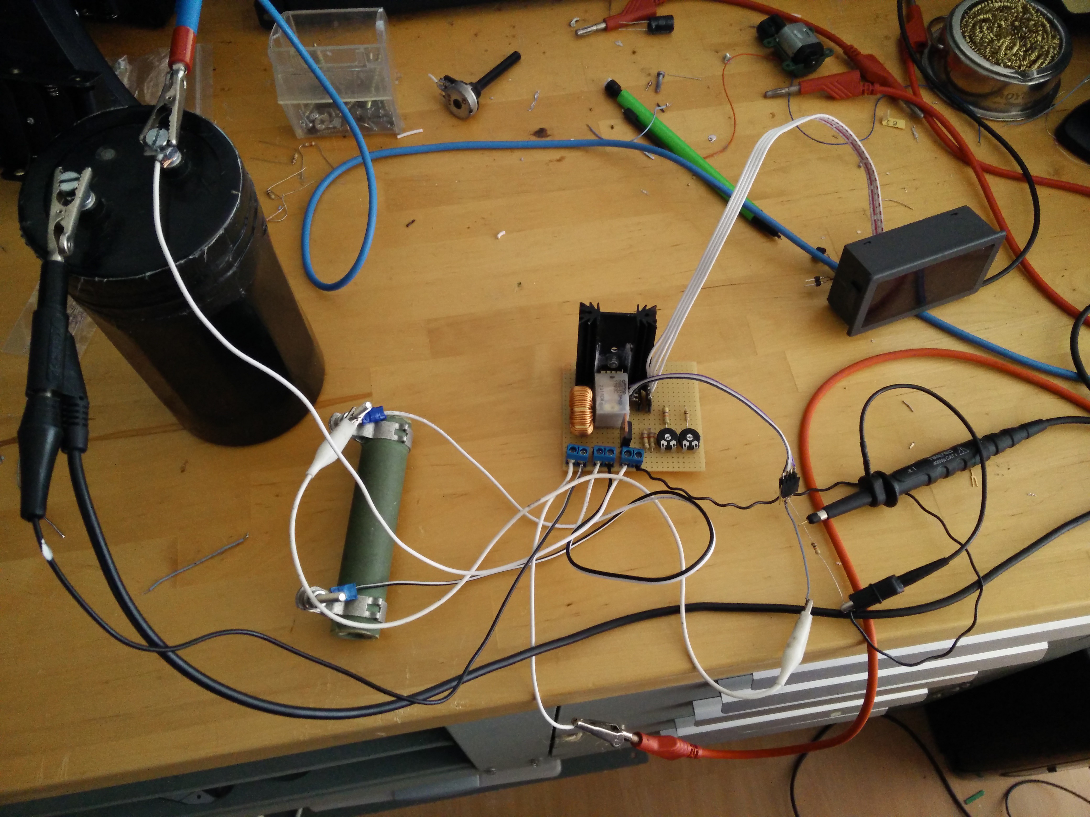
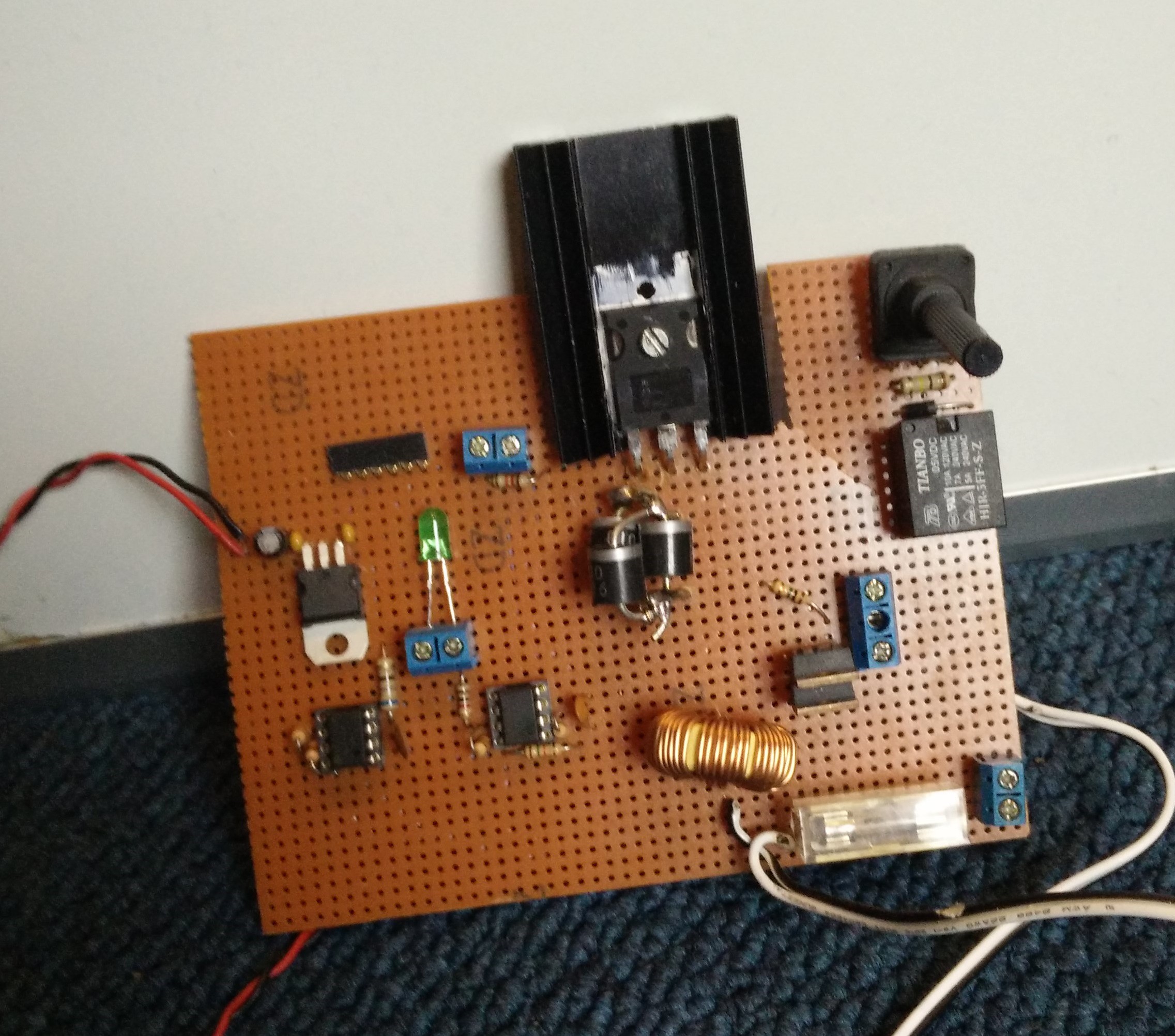
04/19/2015 at 14:15 • 0 commentsAfter a small break, more progress. Wifi is working and can be updated OTA. The ADC is working. Biggest progress is that the charging circuit is build and working. To find a good PWM frequency and duty cycle for the current goal of 1.5 to 2.0 A I set. I created a small test setup using a frequency generator as PWM source.
![]()
![]()
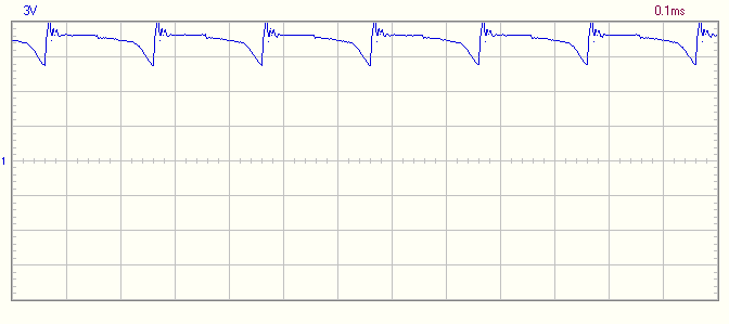
With the test setup I was able to determine that a frequency of 5 KHz with a duty cycle of 50% would result in a current draw around 1.7A. Higher frequency would charge slower and a lower frequency would increase the current without increase the charging speed much. Since the circuit is switching a coil my guess would be that it would generate some noise on the power supply. Oh boy what was I right...
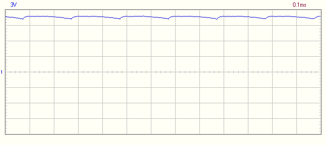
The source is dipping below 9V. To smooth this a bit I added a 470uF cap on the power connector.![]()
That's better![]()
Next up finishing up the code, make the controller board.
-
Schematic update and progess
02/07/2015 at 22:05 • 0 commentsFinally found the time to make some progress. While I was gone for a while I have acquired ESP8266 modules so instead of the NRF24l01+ I'll be using the ESP8266 for wireless communication. Change of component caused a small change in schematic.
Progress on the software part is mostly writing the control of the system. The menu is finished and the ESP8266 is configurable with the menu.
Next up is the PWM out for the charger and the voltage measurement.
-
Schematic and progress update
12/30/2014 at 18:28 • 0 commentsProgress is going slow. Mostly because of university stuff that take most of my time. I did finish the schematic.
Schematic consists of 2 boards one for control and one for power electronics that (dis)charges the capacitor bank.
The plan is to have 4 buttons to navigate the menu and another 4 buttons for switching to fire mode, switching to charge mode, firing and discharging the capacitors. All switches are hardware debounced so programming should be way easier.
Already have the display working after adapting my own display driver from a lasertag project.
-
Teardown mark 1
11/15/2014 at 14:27 • 0 commentsThe mark 1 had some components that needed to be reused in the mark 2.
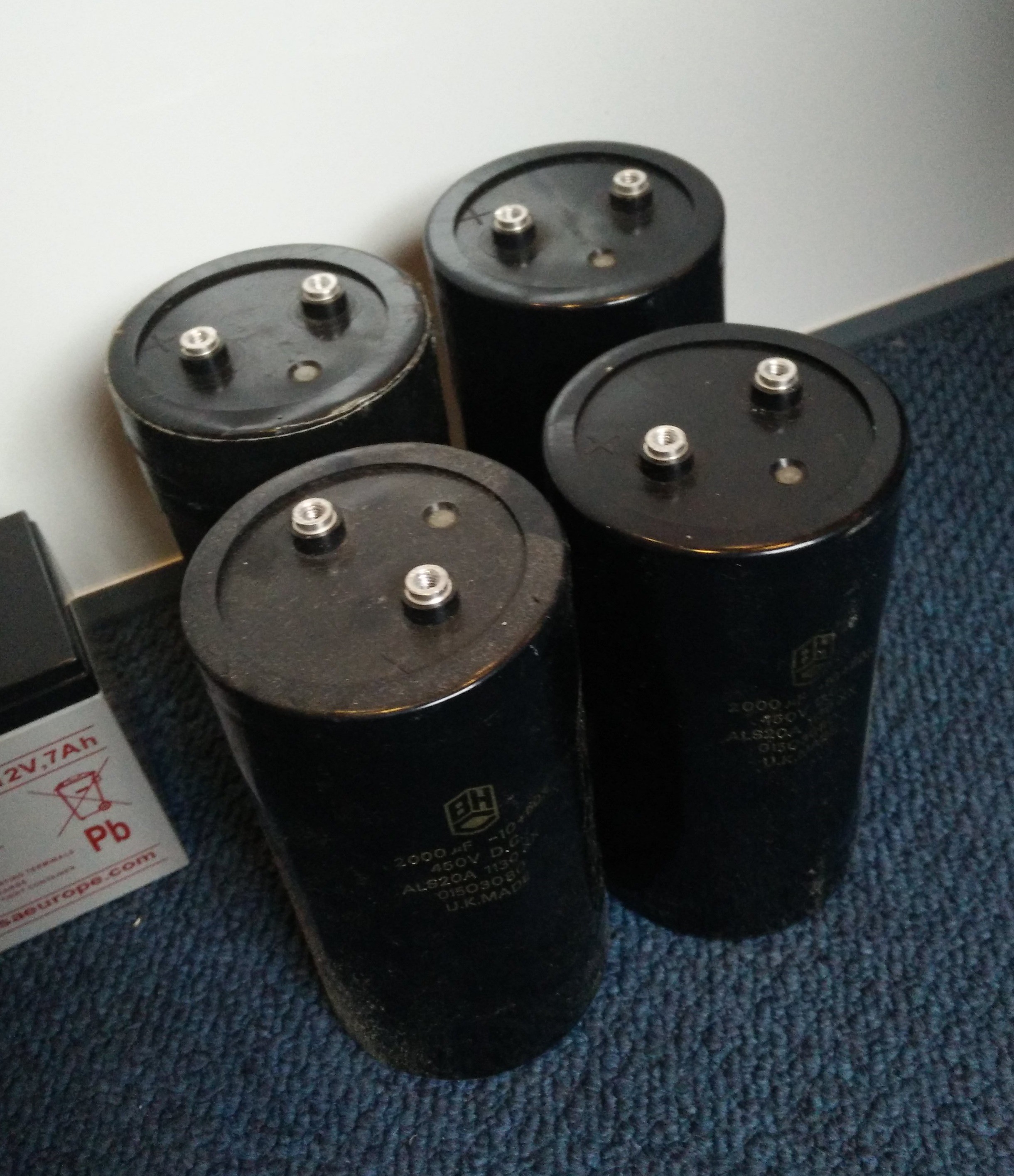
-4x 2000 uF 450V caps
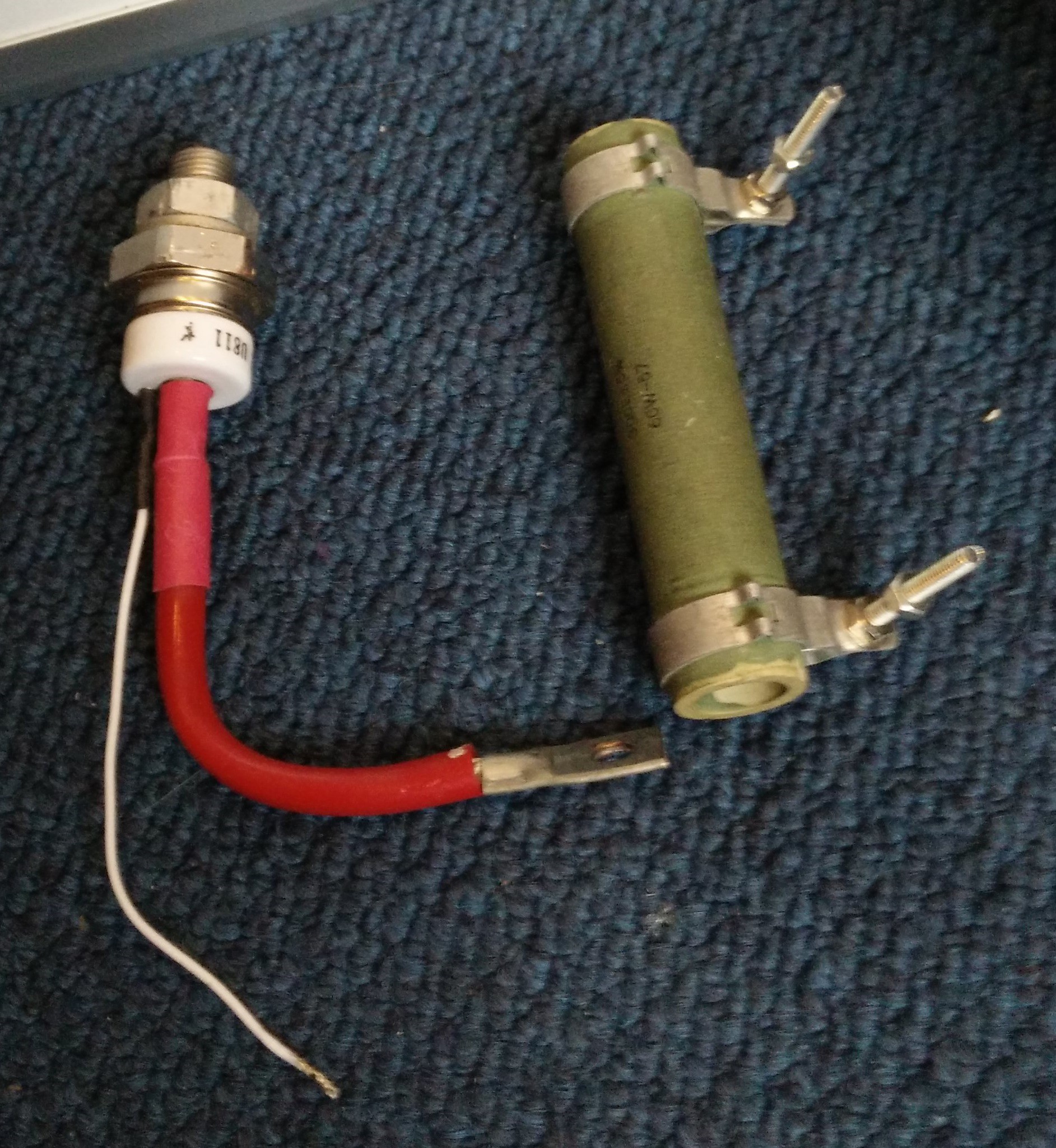
-300Ω 60W resistor used to drain fully charged caps
-600V 30A Thyristor GE B1589142
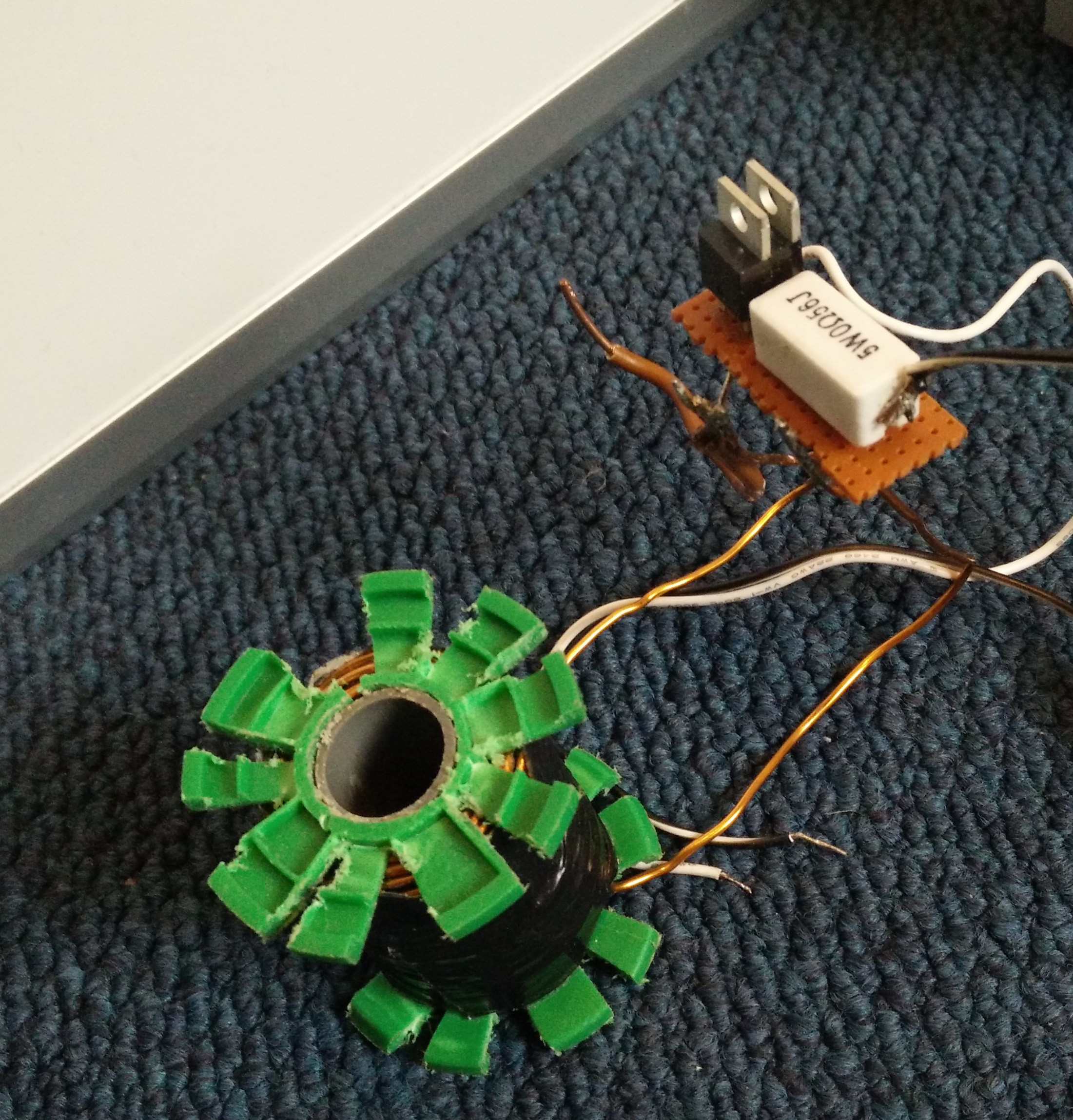
-Coil mark1 with 2x MUR860 diode and 0.56Ω 5W resistorAlso the mark 1 PCB that I made without any knowledge what all the components did. With the beauty of 3 parallel diodes soldered on each other.
![]()
![]()
![]()
![]()