0%
0%
Decimal to Binary to Hexadecimal Converter
An overly mechanical device that will convert decimal numbers to binary and hexadecimal.
 Anthony Garofalo
Become a Hackaday.io member
Already have an account? Log in.
Just one more thing
To make the experience fit your profile, pick a username and tell us what interests you.
Pick an awesome username
hackaday.io/
Your profile's URL: hackaday.io/username. Max 25 alphanumeric characters.
Pick a few interests
Projects that share your interests
People that share your interests


 danjovic
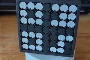
 Chamu Rajasekera
 Onion.io
 Lubomir Jagos
Let me know if you have any questions.