David H Haffner Sr
-
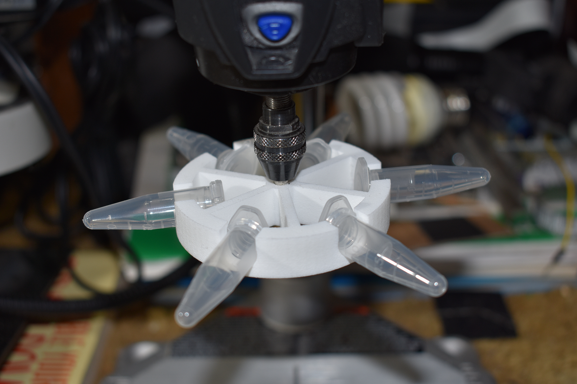
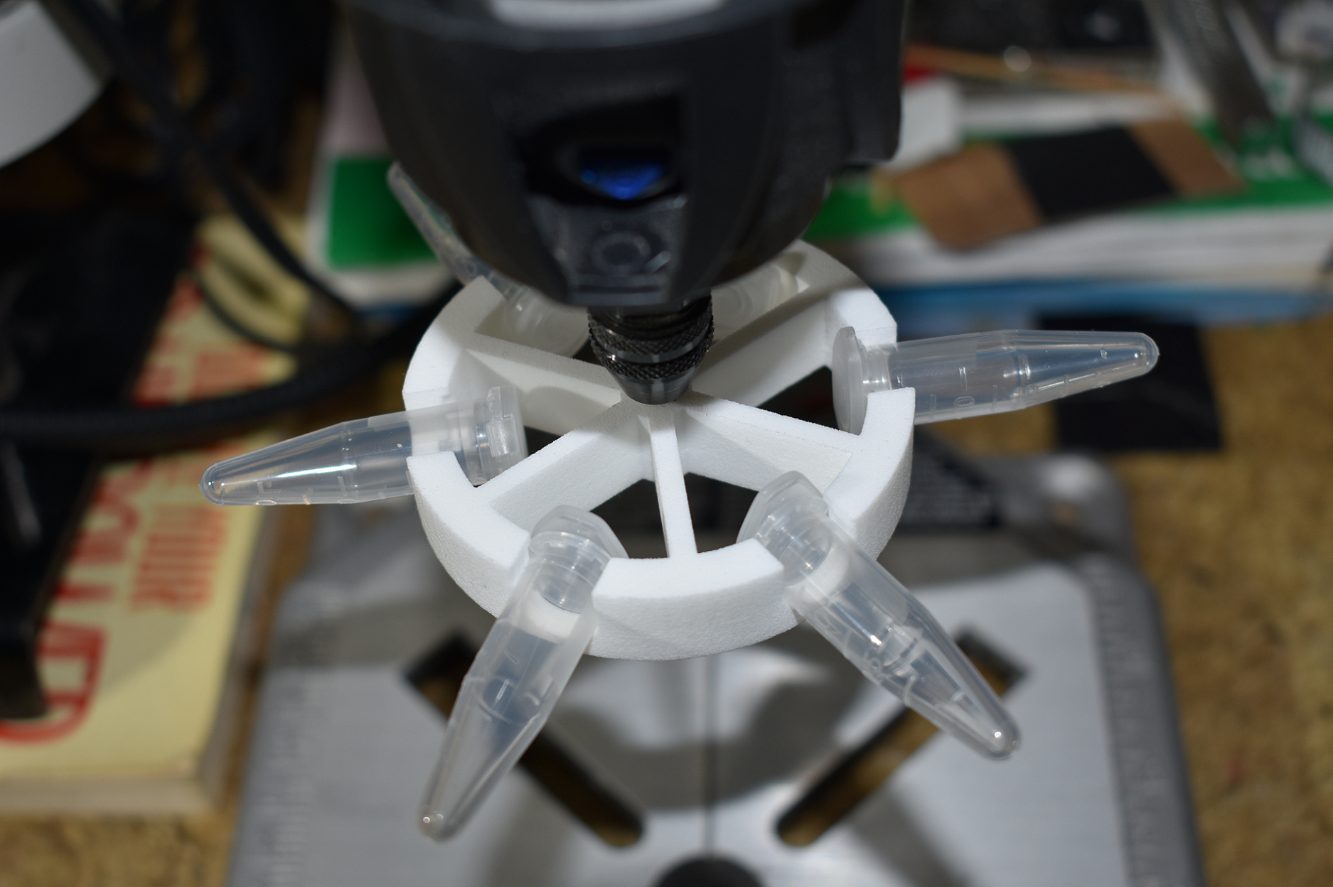
DremelFuge - A One-Piece Centrifuge for Rotary Tools
03/12/2018 at 17:46 • 0 commentsYep, I found this little gem on the web 2 weeks ago and downloaded the mesh file and got it 3d printed (the material I used was Nylon-PA12) and man alive does it work! Only cost me $7.00 US currency. This little 3d printed lab quality centrifuge when coupled with a good Dremel rotory tool (35000 rpm,) can spin down a sample @ 2136.498 times the force of gravity, enough for a quality DNA extraction.
Here is some pics of the one I got printed and I have already tested it @ full speed with 6 1.5ml sample tubes.
![]()
![]()
![]()
This design is open source and can be found here:
http://www.thingiverse.com/thing:1483
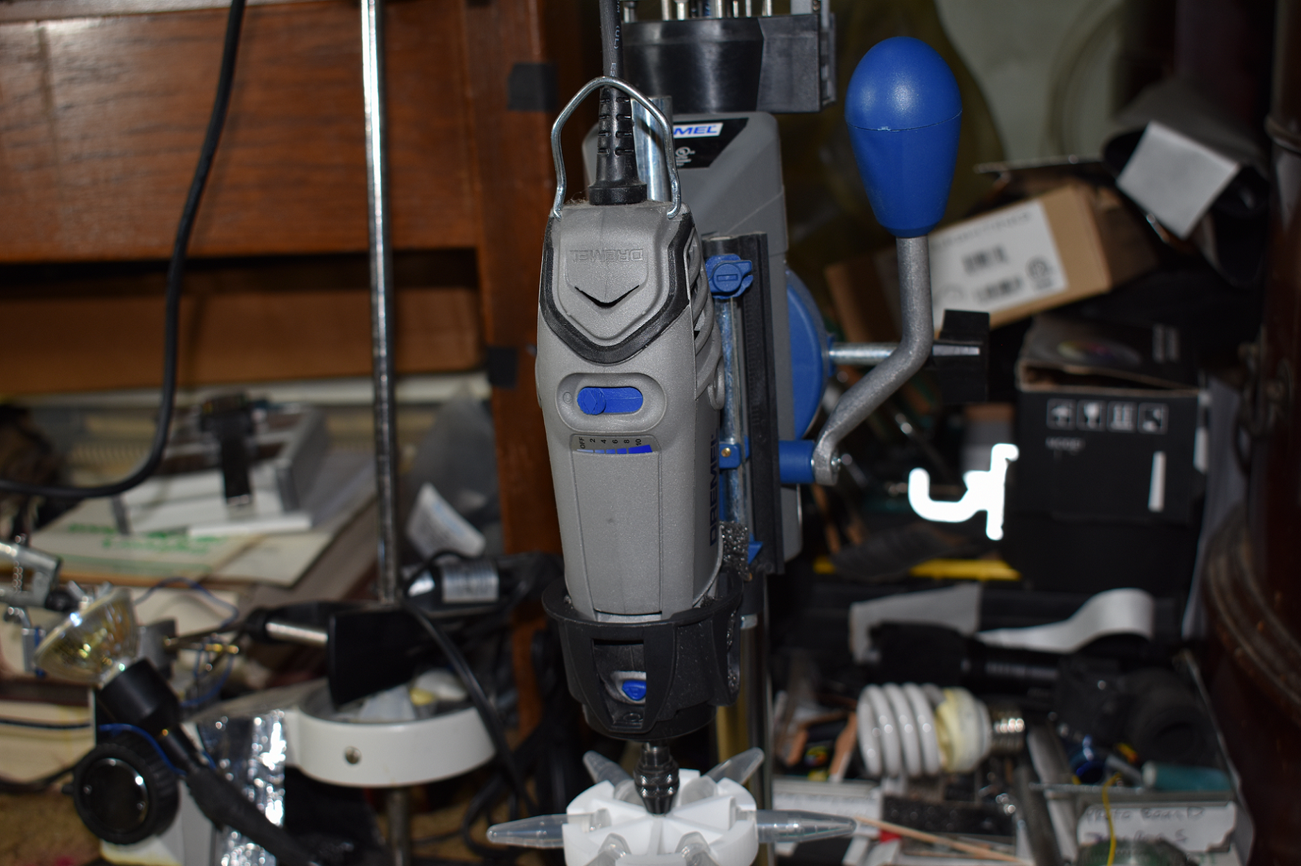
This my Dremel rotory model# and specs:
Dremel model#3000 rpms - 5000 - 35000
Max
G-force @ 35000 rpm
= 2136.498Shaft Radius = 0.156 cm (this is the shaft I used since the centrifuge center hole was designed to accomodate a standard Dremel shaft accessory.)
Rpm's = 35000 -
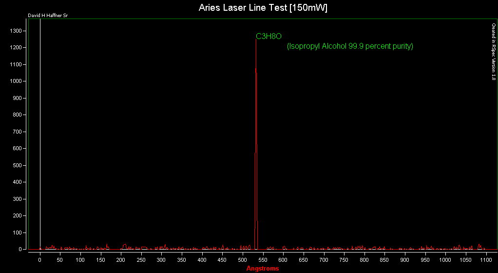
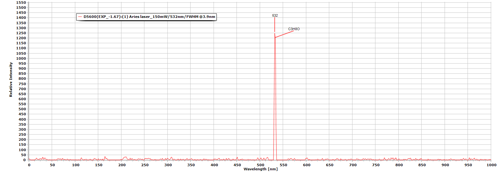
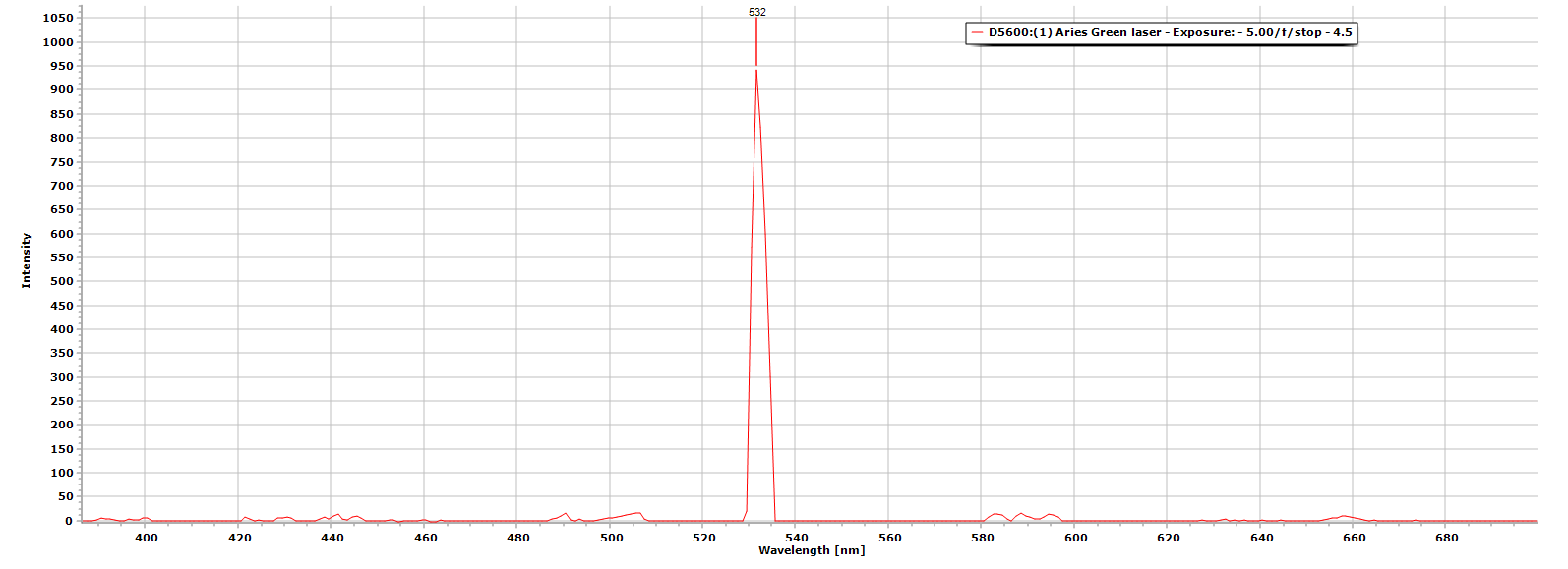
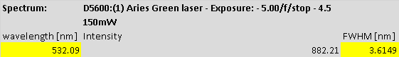
Laser Line Test #2 [150mW] Aries Laser [532nm]
03/11/2018 at 16:49 • 0 commentsGood results with this test, 1218 Angstroms of intensity counts @ 532.15nm CW (center wavelength)
FWHM @ 3.9nm
![]()
![]()
The medium I used was Isopropyl alcohol, 99.9% lab grade purity thru a standard 1cm quartz cuvette.
-
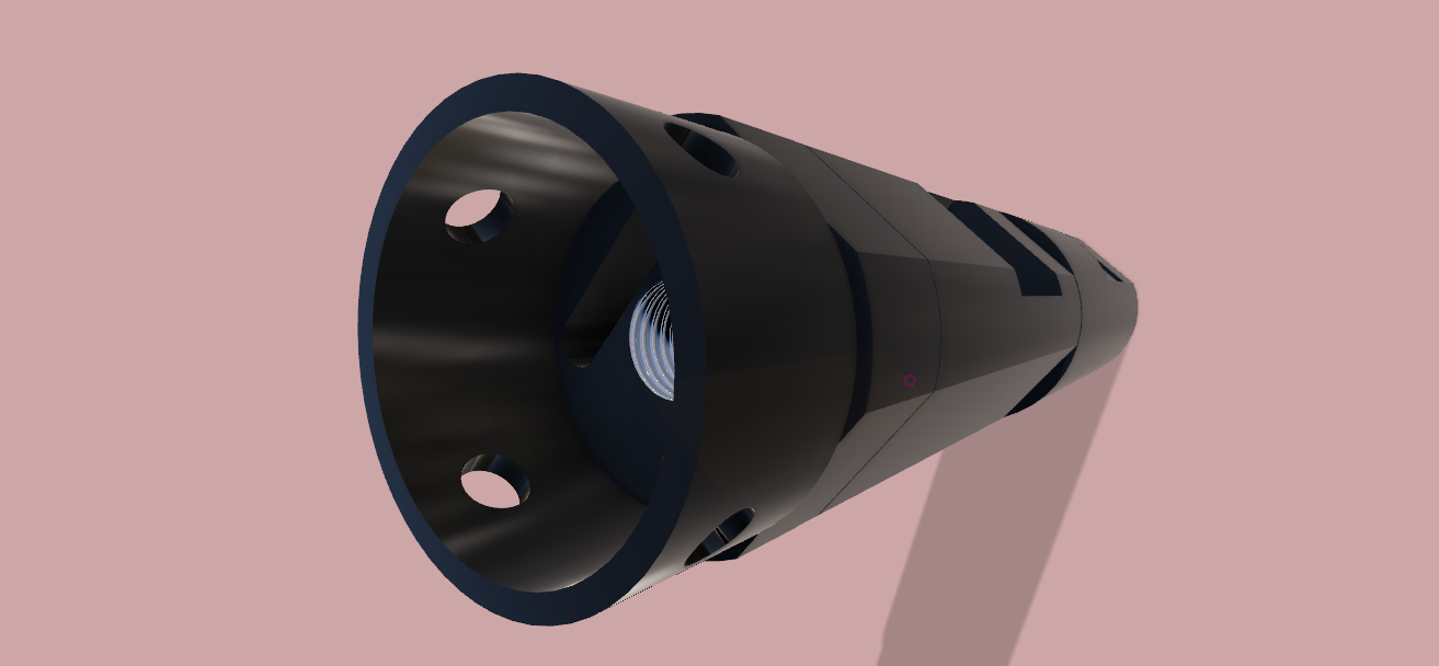
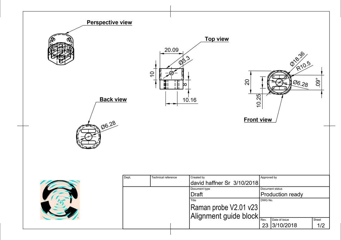
Final Production Ready Raman Probe Version (23)
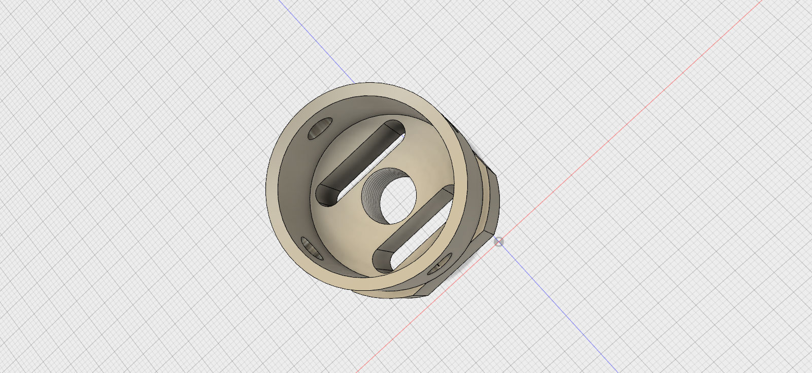
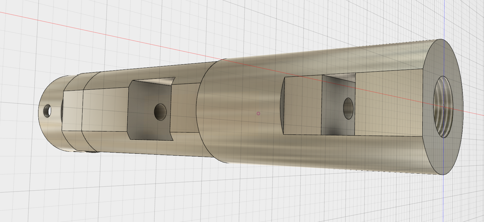
03/10/2018 at 21:18 • 0 commentsHere it is, ready to be 3D printed along with the laser alignment guide, this version will be made out of Nylon-PA12 and dyed glossy black (polished), same with the alignment guide block.
![]()
![]()
Below is the drwaing for the Main Raman probe unit
![]()
![]()
Below is the drawing for the alignment guide (laser)
![]()
![]()
I will uploading the .STL mesh files for this shortly...
-
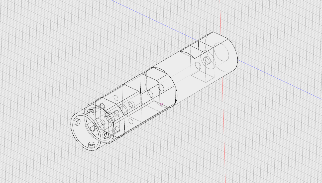
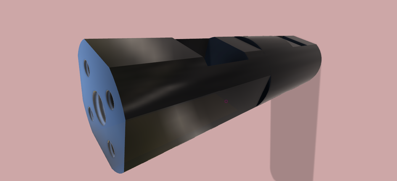
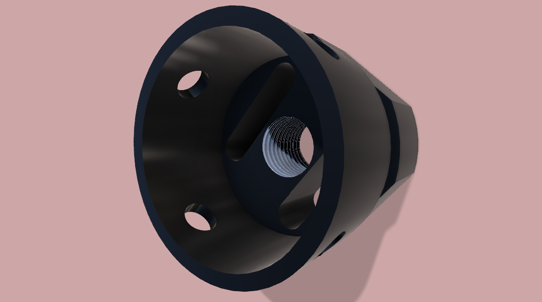
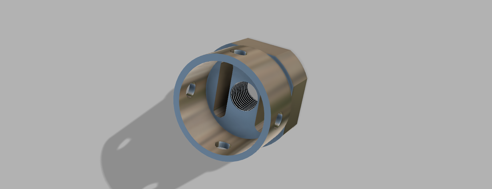
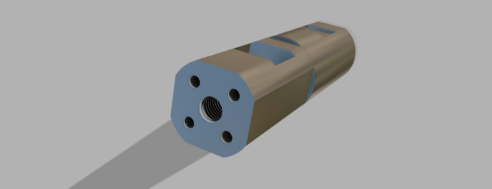
Raman Probe 2.0.1 V23 re-designed Using Fusion 360
03/09/2018 at 12:30 • 0 commentsI completely re-designed the concept of my Raman probe using autocad Fusion 360, which is completely an awesome CAD program!
This is the complete unit below
![]()
This is the re-designed laser alignment block which attaches to the probe
![]()
Below is the main body
![]()
![]()
![]()
It took me about half the day to learn how to use Fusion 360 and definitely worth every effort :)
-
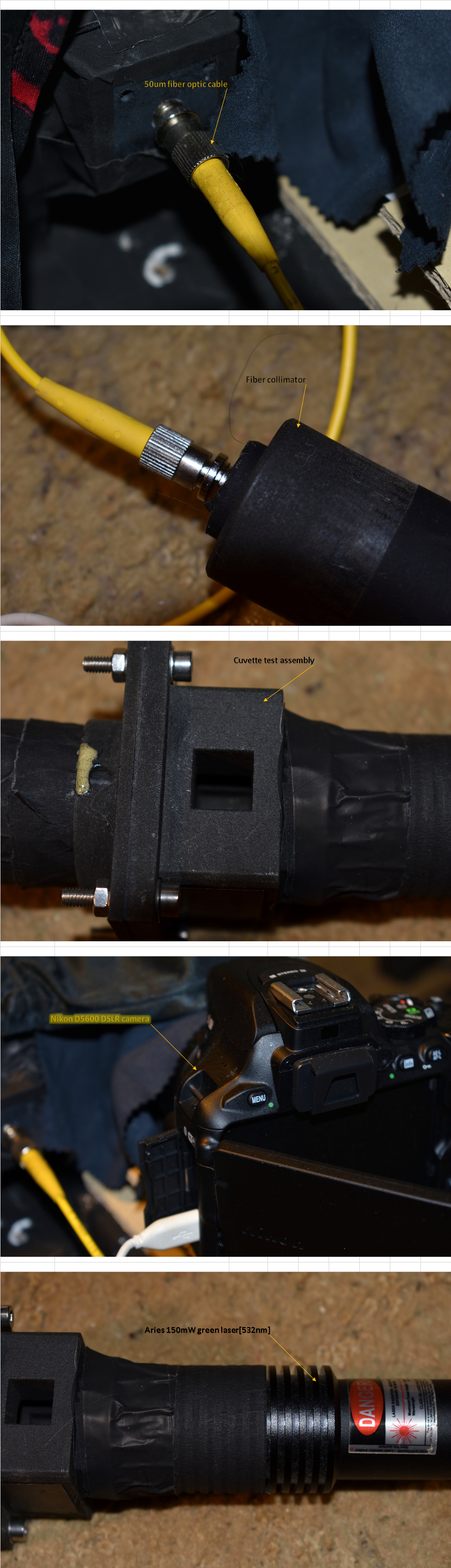
Technique & skill More Important Than Size Of Fiber Optic Core...
03/06/2018 at 15:04 • 0 commentsI did this experiment as a demonstration to illustrate the importance of technique and skill when it comes to dealing with fiber optical equipment and it's related optics. I do have some experience in this field, thanks to my time in Bell Atlantic and Verizon (telecommunications companies,) yes it is important when dealing with very weak Raman signals that the size of the fiber core is relevant, but is NOT the only gospel in the good book, alignment, aperture size, core material and cladding all play a significant part in acquiring the best Raman signals possible.
That's not the only game in town though, focal length, selecting the correct reflective mirror, diffraction grating and laser selection all work together to achieve a proper Raman spectrum.
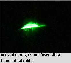
I'm presenting a laser spectrum below imaged through a 50um fiber optic cable, very small core, fused silica. I constructed a test platform to simulate the Raman probe with my laser attached and aligned with the fiber optic collimator at the exit area.
![]()
This is the laser spectrum itself ( wavelength range set @ 400 - 700nm)
![]()
![]()
![]()
So as you can see, it is possible to successfully image a very weak laser image with proper skill and technique, specs for this image capture are:
f/stop - 4.5 (aperture)
exposure time: 1/60 sec
exposure bias - minus 5 step
focal length - 18mm
-
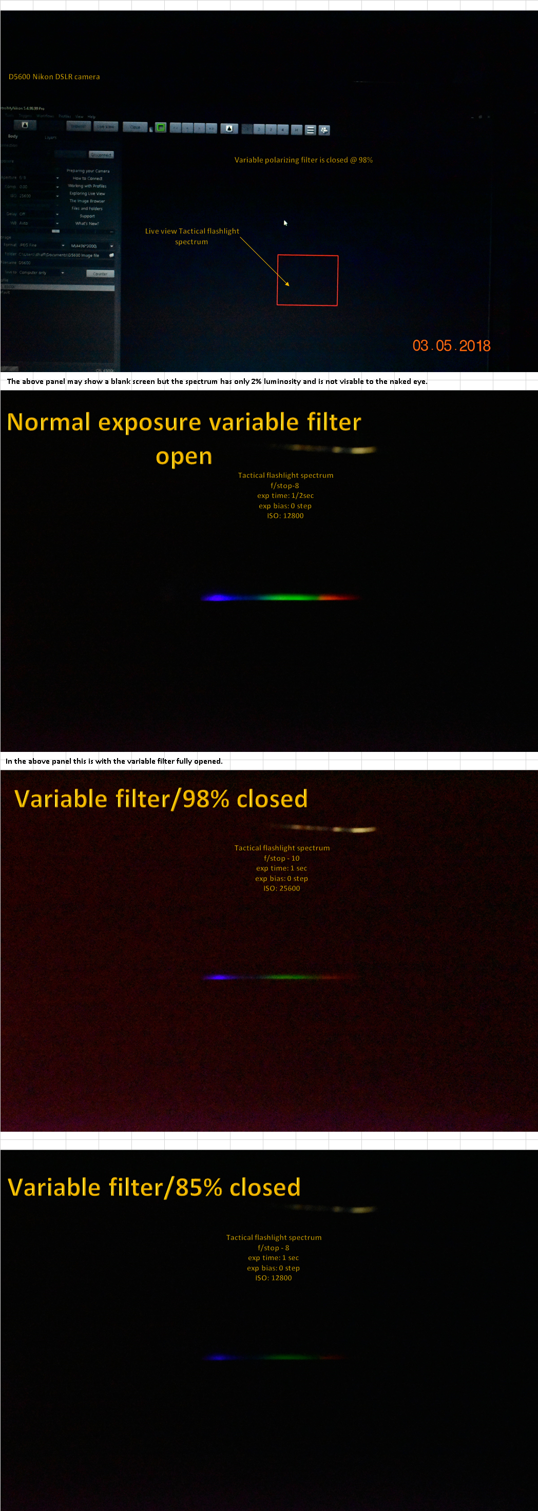
Exposure & Luminosity Testing for Raman Probe V2.0.1b
03/05/2018 at 17:41 • 0 commentsI had to finally conduct this critical test, especially since Raman signals are so very weak and luminosity can suffer a bit because of the notch filter I will be using, so I used my tactical flashlight (Bell & Howell...yeah the one on T.V.) and my variable polarizing filter (which graduates from fully opened to fully closed 0 - 100 %)
![]()
The purpose here was clear and logical, the 1st panel showed a blank live screen coming from my camera, the spectrum is there you just can't see it because the luminosity is so low. The following panels show the progression from normal shutter exposure settings to the most extreme ISO sensitivity @ 25600.
The primary wavelengths are in the green (514nm - 590nm) and orange to red (590nm - 614nm). Which I can verifiably resolve with this camera's cmos detector.
-
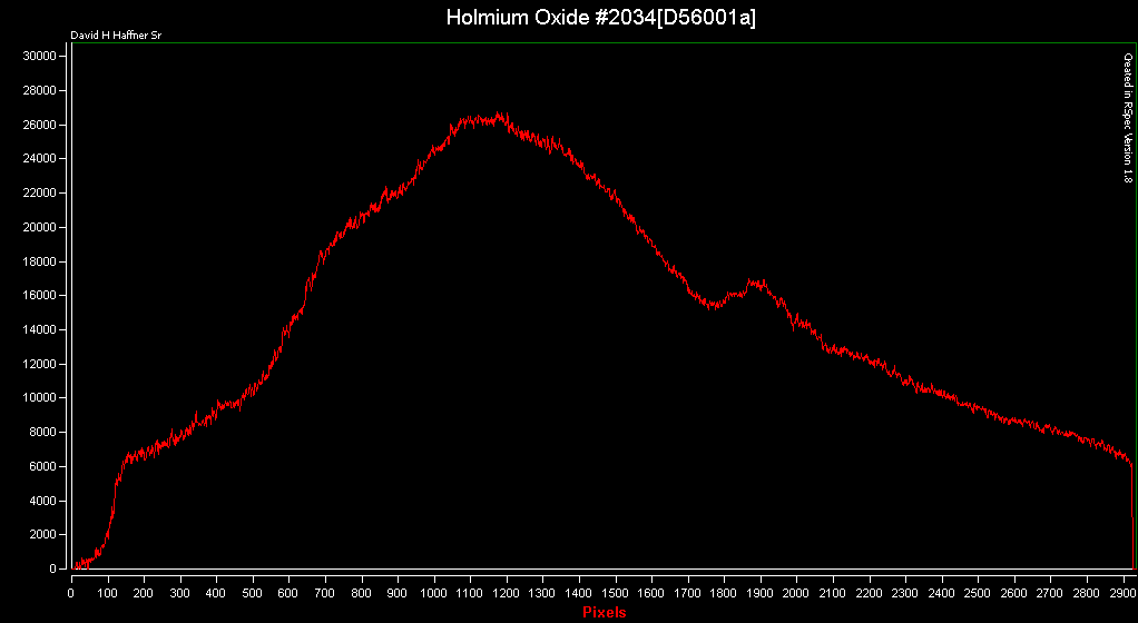
Verified AOI/Focal Distance for Raman Probe Design & Spectrometer Enclosure
03/03/2018 at 15:22 • 0 comments*note, the term AOI means "angle of incidence." (the angle that an incident line or ray makes with a perpendicular to the surface at the point of incidence.)
This is pertaining to the diffraction grating.
Focal distance means the collmination of light focused from the mirror to the diffraction grating.
Ok, for this test I couldn't use the POF(plastic optical fiber,) or my regular fiber optical cable, but that's ok because this was purely an absorption test to prove how well my Nikon D5600 camera's sensor can resolve the peaks of a Holmium Oxide wavelength calibration standard as compared to using my previous ELP machine vision cam.
She blows it away! So, I am very confident now that when I put together all the components of this setup that I will be able to successfully resolve Raman peak signals @ the wavelengths according to the research paper upon which this project is based.
Kind of like verifying someone else's experiment, not that I don't believe them, but I've never had the chance before to verify someone else's work before and this is very thrilling to me :)
1st up are the RAW data files from RSpec, this is the reference spectrum (my Solux lamp.)
![]()
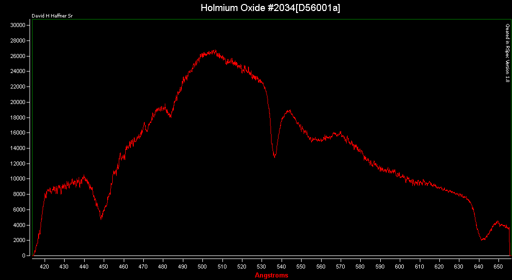
Next is the sample spectrum, Holmium oxide#2034. ( F/stop - 5.6/exposure time[1/10 sec] ISO - 12800
focal length - 34mm
![]()
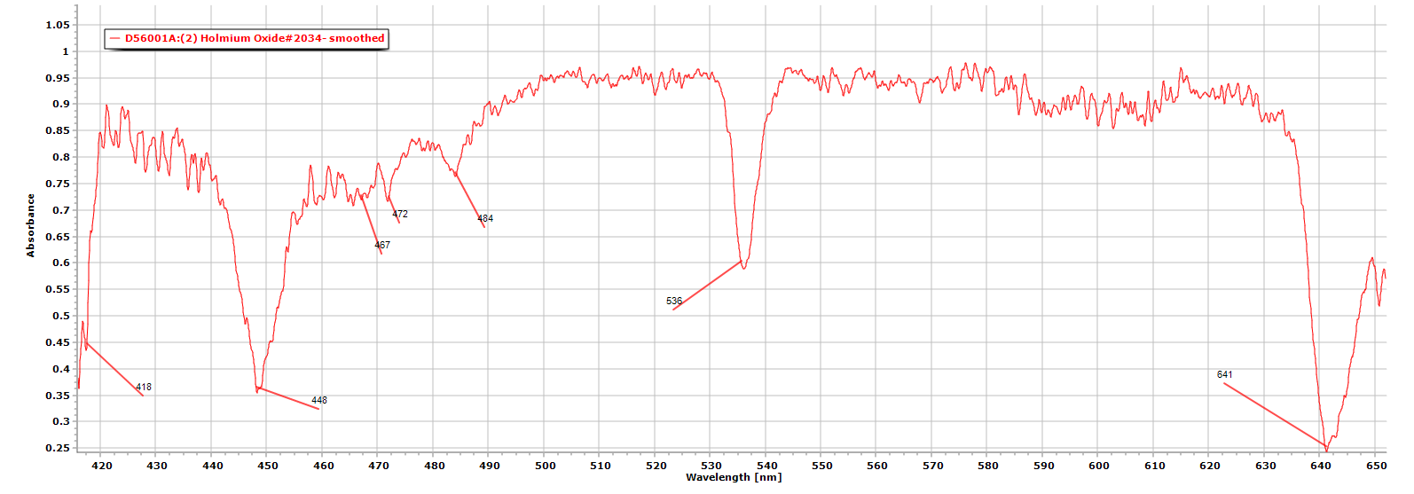
This is the sample (Holmium oxide,) processed using Spectragryph 1.2.8
![]()
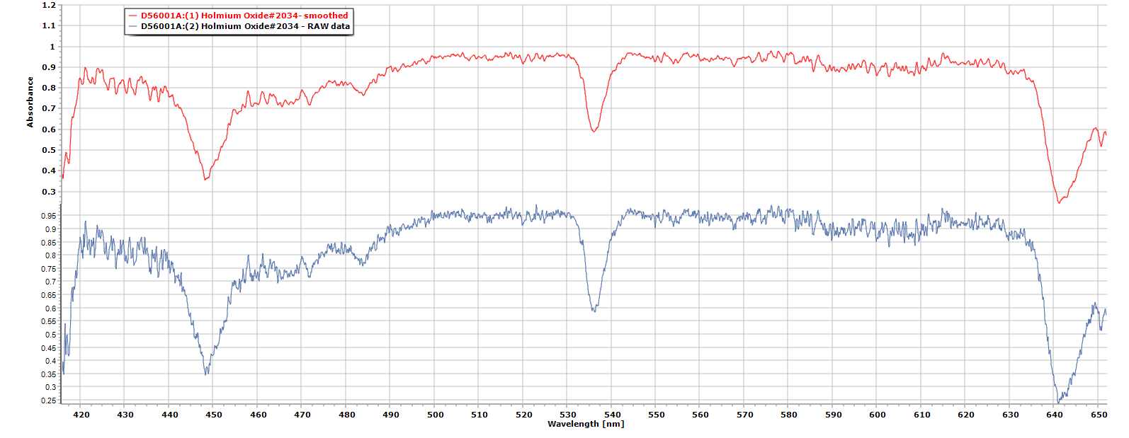
This is both the raw sample after it is divided by the reference spectrum (Solux lamp) and the smoothed sample (cleaned up,) caveat about using too much smoothing, every calculation of order removes a little bit of actual data so be careful and only use it if U really need to.
![]()
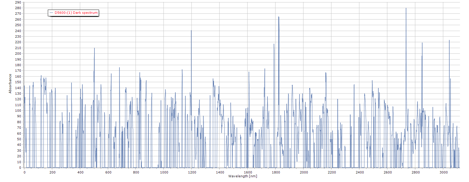
A Dark frame was also taken to subtract from both the sample and reference, in order to remove as much noise as possible.
![]()
In conclusion, here I was able to resolve 6 peaks with clarity just by using "free-air" light transmission and correct focusing. By using proper focusing and spectroscopy techniques a cmos sensor can certainly be utilized as a viable means of detecting not only wavelengths in the UV/VIS range but also in the Raman as well.
-
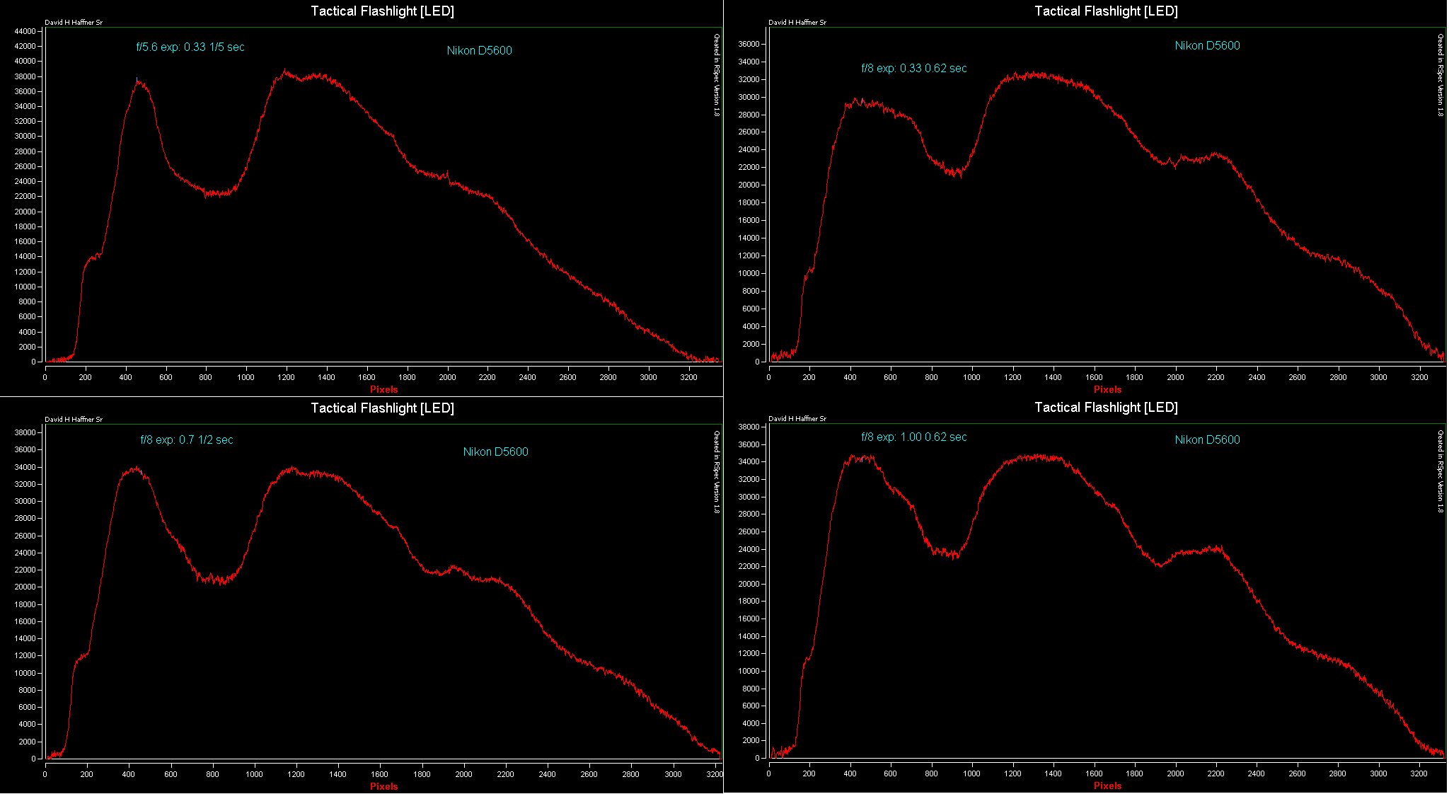
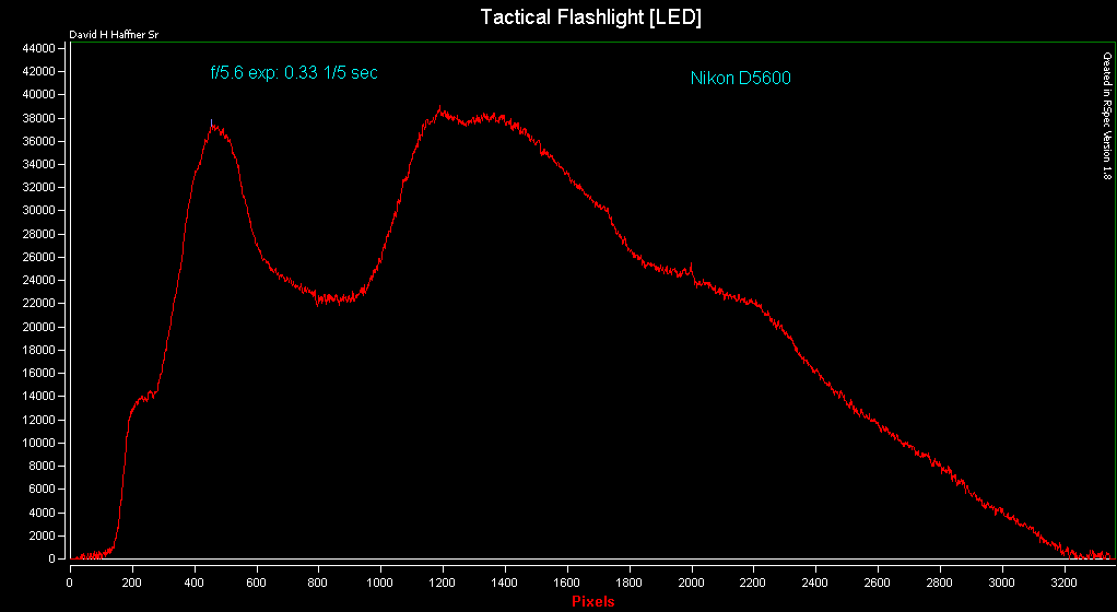
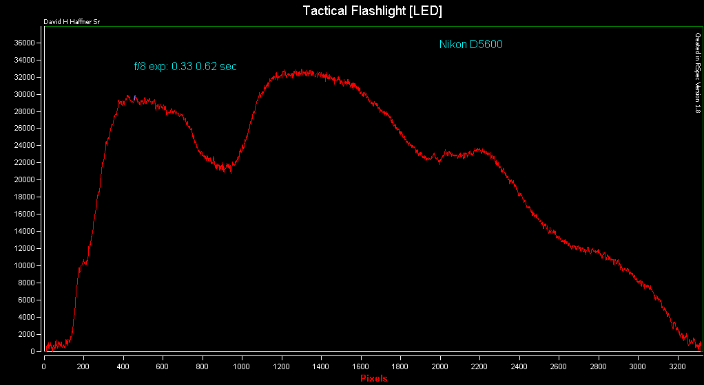
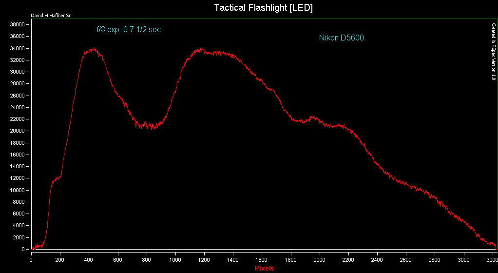
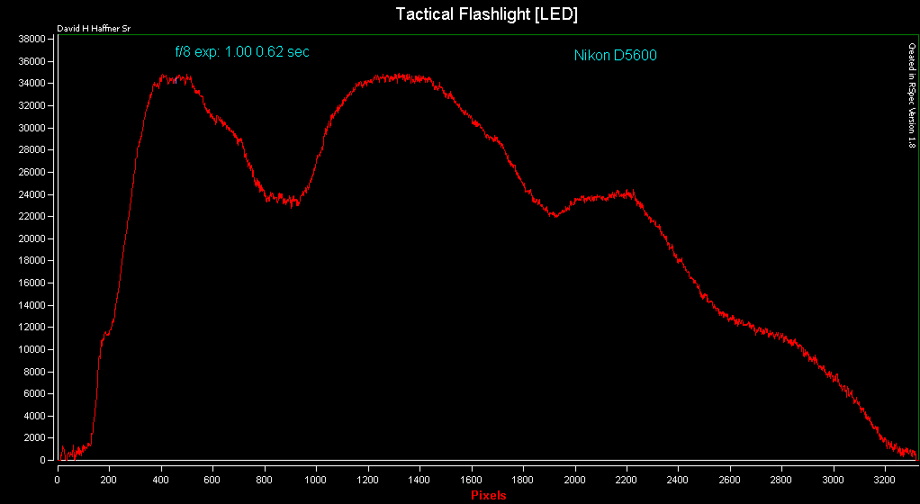
Learning About F/stop and Exposure time for The Nikon D5600
03/02/2018 at 12:42 • 0 commentsStill using my POF (plastic optical fiber) setup, I shot a few spectral images of my Tactical LED flashlight @ different f/stop and exposure time intervals so I can start to get a good feel and understanding how this camera works and these are some of the results presented from RSpec spectroscopy processing capture software:
![]()
![]()
![]()
![]()
![]()
-
Winning 1st Prize by Stealing Someone Else's Hard Work...
03/01/2018 at 15:09 • 4 commentsI felt compelled to talk a little about personal honor and how it may be sorely lacking today in this "open source" continuum we call the digital verse. When I started my Raman Probe project, I got the inspiration for it by researching homemade raman spectrometers on Google images, I ran into this interesting project that seemed like it may be what I had been looking for, since my previous attempt at this technique just where not panning out.
I certainly was doing something wrong and needed to learn a lot more, so I studied this paper; http://article.sapub.org/10.5923.j.jlce.20150304.02.html , still kinda frustrating because they left a lot of critical information out pertaining to the build part, good job on the Raman data part, but it left me having to figure out how they arrived at focal distances and what not.
Anyway, the point of this is, I could have just straight up ripped off their project piece by piece, giving no credit and hoping no one would ever find it on the internet...Ha, ha, ha, always remember if YOU found it, then someone else can too.
I for one, am a man of honor, they have a creative commons license so I not only gave them credit, also the link to the research paper and the group of individuals involved,
Secondly, I redesigned most of their project so it would work for me, so I could design it on FreeCad. I redesigned the spectrometer enclosure, the probe itself and the mirror and diffraction grating and re-calculated errors I found in their original paper and fixed them.
This is truly what is meant by "inspired by."
A real genuis, @Alain Mauer has a project called; Arduino Glasses a HMD for Multimeter, he clearly put in the hard work and intellect necessary to pull that off, he deserves the credit...open source or not, the individual who blatantly ripped it off, won 1st prize in a contest and is now selling it for a profit, and getting comments about what a "genius" he is for doing it.
He has almost 1/2 a million views on Youtube, that's unacceptable everyone, most of us here are former engineers, programmers and what not from a various backgrounds but we all have the same thing in common, respect and honor as human beings, it's not really that hard to police ourselves and call out those who choose to commit the cardinal sin of intellectual theft for profit.
Lets just try and think about that a little more in our endeavours when we are creating such wonderful devices.
-
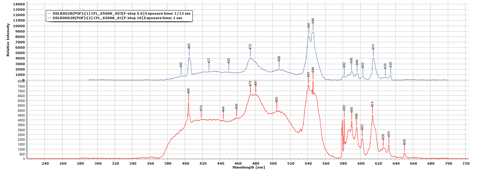
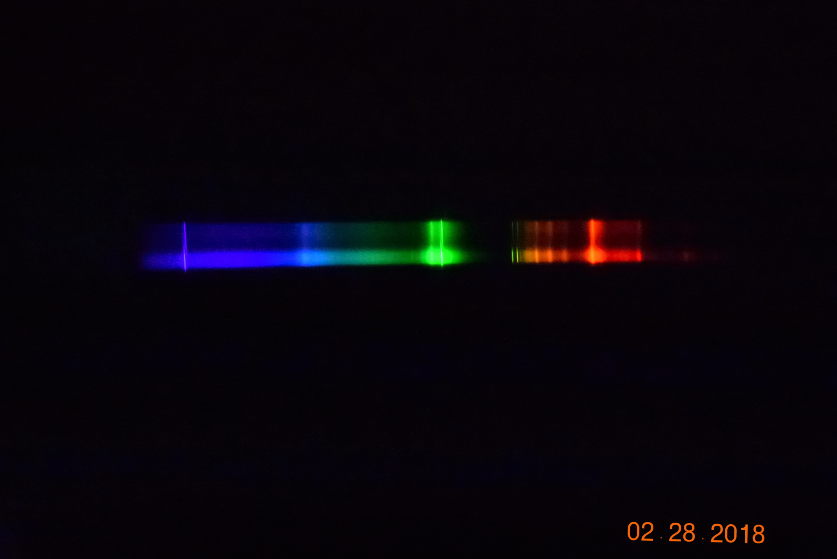
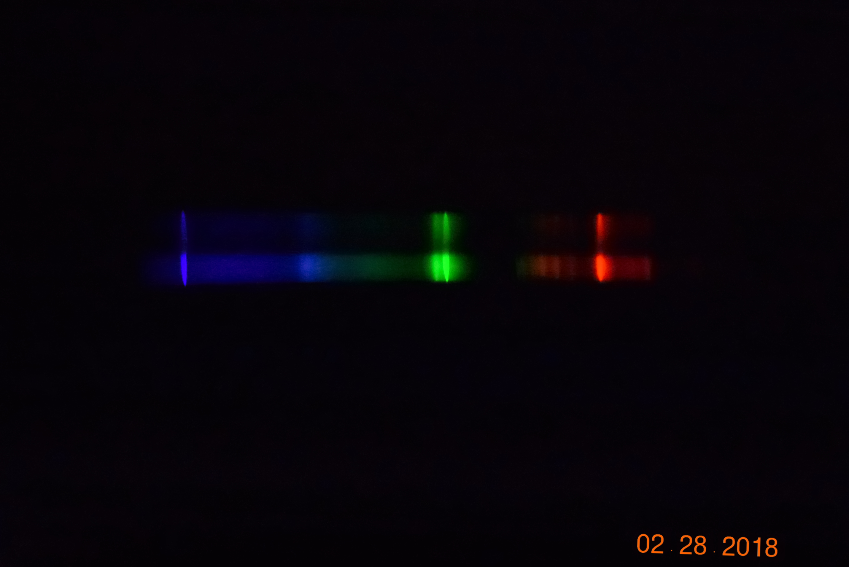
Experimenting With POF (plastic optical fiber) Part III
02/28/2018 at 22:19 • 0 commentsThis time I am using my 6500K CFL (compact fluorescent lamp) at two different exposure settings: 1) F-stop @ 5.6 and F-stop @ 10.
![]()
As you can tell though, the plastic fiber is really noisy no matter how I try and clean up the signal, either in the Nikon capture software or in Spectragryph processing software, still it is an interesting experiment because this is the same type of optical fiber that is used in the automotive manufacturing industry today because it is inexpensive, reliable and easy to work with.
My original project I had in mind for it was a fiber optic telecommunication's device using a photo transistor as the light transfer medium, who knows I still may strike that project back up :)
![]()
The image above is F-stop 10 exposure time: 1 sec ISO-25600
![]()
The image above is F-stop 5.6 exosure time: 1/13 sec ISO 25600
3D Printable Raman Probe
This a 100% 3D printed Transmission Raman Probe (low resolution) W/built-in cuvette holder/Raman filter