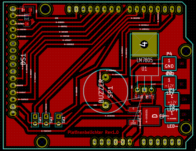
This is the Arduino Shield for the UV Exposure Unit. It should be the first PCB you create on the UV Exposure Unit and from there on you can use it to create even more PCBs; )
A project log for UV Exposure Unit
UV Exposure Unit reproducable in every Hackerspace with a Laser-Cutter.
This is the Arduino Shield for the UV Exposure Unit. It should be the first PCB you create on the UV Exposure Unit and from there on you can use it to create even more PCBs; )
Discussions
Become a Hackaday.io Member
Create an account to leave a comment. Already have an account? Log In.
Any reason for the weird dogleg trace in the middle? It seems you could just route it parallel to the two traces above/left of it. It does look interesting, though.
Are you sure? yes | no
KiCAD didn't want to create those traces parallel to the other one somehow, so I ended up with this solution.
Are you sure? yes | no
Seems like you have missed a GND connection on the FET and a CAP. It may help if you move the jumpers for the SPI closer to the according shield pins and Mirror those connector pins so the FET can be closer to its shield pin, too.
Are you sure? yes | no
Moving those parts is an good idea, but it will have to wait until my exams are finished
Are you sure? yes | no