-
1Step 1
Make you the PCB and get the components and any standard 60mm 4-wire fan will probably do the job. I used a JMC "6015-12HB APW" that I had lying around. The exact the same fan is readily available on eBay.
I used eagle to design my PCB, and the files is available on my GitHub.
-
2Step 2
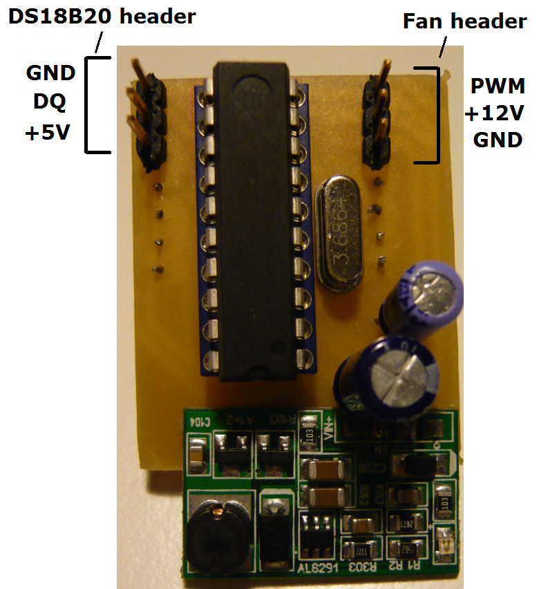
Solder the components to the board. To connect the fan controller PCB to the expansion slot I used solid wire because the holes in the expansion slot is not wide enough to support a standard 2.54mm pin header.
To program the micro controller I used a STK500 kit with the ISP header connected to a breadboard. The programming files is file available on my Github so you can program it you self.
-
3Step 3
Solder 3 wires to the DS18B20 chip, and use heat shrink around the exporest wires so they not short. To the connection to the board I do not recommend to use a female header connector because off the hight to the case. I used it on one of the headers and it could just fit in the case, with the wires rubbing against the case top. Instead I recommend to solder the wires directly on to the headers or the PCB.
![]()
Now you could test the circuit to see if it is working by connecting to an external 5V source before solder it to to the load. If you set the MIN, OFF and START control values to a value little over the ambient temperature, and by touching the temperature sensor the fan will turn on and begin to run faster the more you heat it.
IMPORTANT the fan can not directly be connected to the fan by the header of the PCB so you need so sort of converter.
-
4Step 4
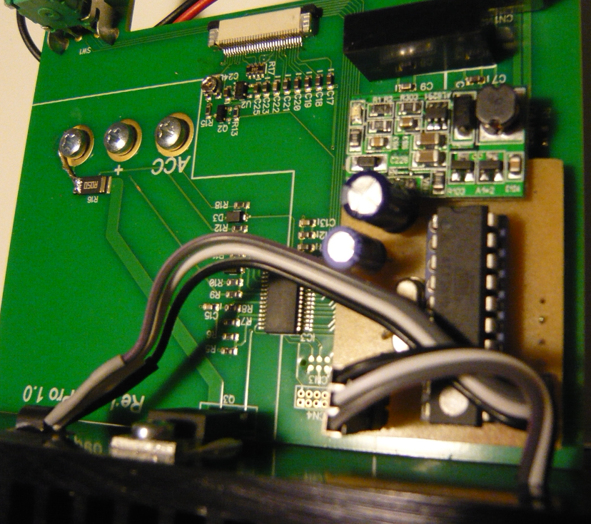
Find 3 thin wires for the fan and test that it can get through the small hole in the heat sink, and solder them to the PCB.
Now it is time to solder the PCB to the expansion slot.
Glue the temperature sensor to the heat sink and get the 3 fan wires through the hole in the heat sink.
![]()
When they are through solder a 4x1 pin header to the wires, and connect it to the fan plug. Screw the fan to the heatsink with two M3 bolts. I also glued the fan plug to the heat sink to hold the wires in place.
![]()
-
5Step 5
When everything is assembled now it is time to test it, and maybe set the control values. I found that the following values fit good to my setup.
MAX = 49°C.----- Is set to 49°C because measurements a little over 50°C triggers the overtemp protection.
MIN = 40°C
START = 39°C
OFF = 38°C
MIN DUTY = 20%.----- Is set to 20% because any lower value do not allow the fan to spin slower.
Fan controller for Re:Load Pro
ATtiny microcontroller fan controller, with configurable control variables over the USB interface.

Discussions
Become a Hackaday.io Member
Create an account to leave a comment. Already have an account? Log In.