Christmas Snowflake Sculpture
WS8212 LED strips embedded in an interactive Christmas Display
WS8212 LED strips embedded in an interactive Christmas Display
To make the experience fit your profile, pick a username and tell us what interests you.
We found and based on your interests.
Did an update to the sculpture about a year ago to set up the interactivity. Here's a video of me while I'm working on it.
With the strips built, and the software more or less worked out, it was time to install my stuff in the sculpture. I travelled to FluxWorx in Ottawa and met the intrepid crew building the 20 foot structure out of aluminum and glass. I had hoped to install everything at this stage, but schedules don't always match up. Flux were finishing off one half, while the other was still being welded. Before we could add the strips we had to install the Sensacells.
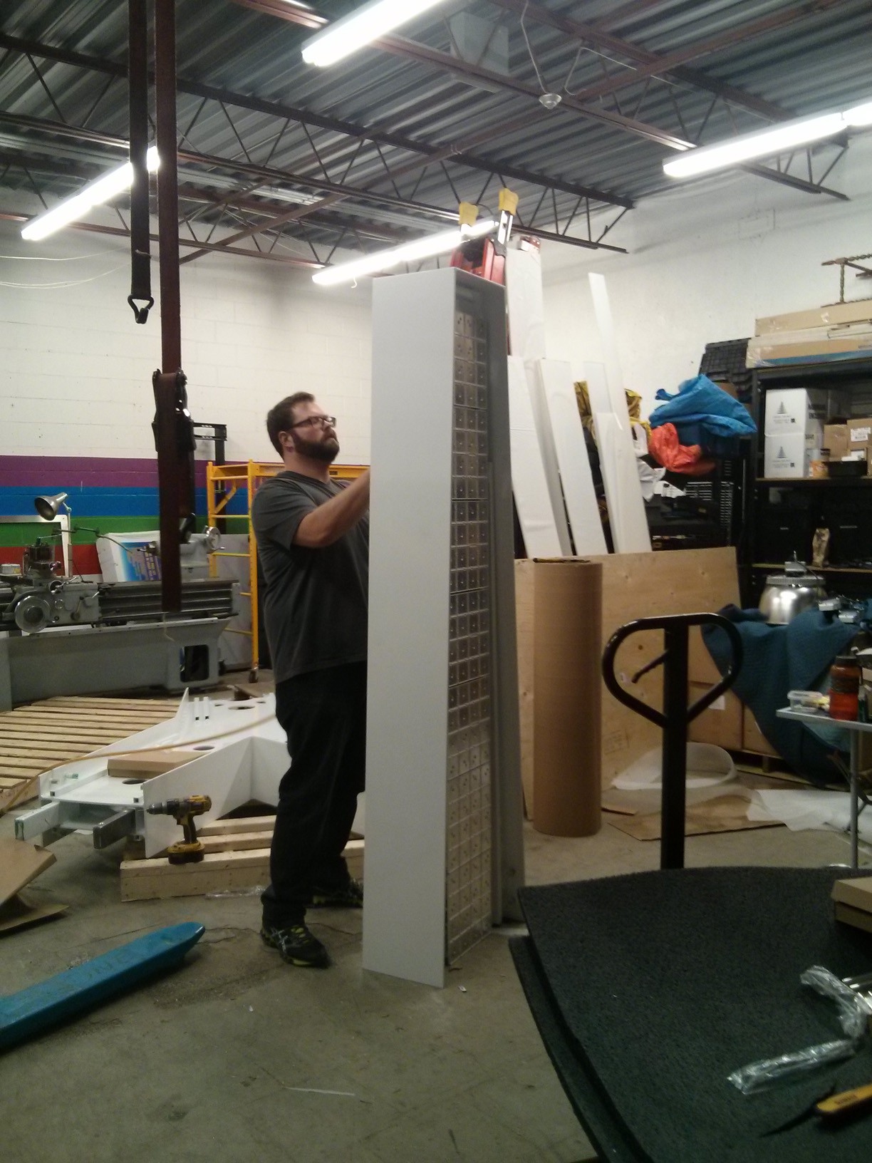
It took about a day before I could put the strips in and fire them up. But we were all relieved that with all the lighting integrated into at least one section of the body, that the project was starting to come together.
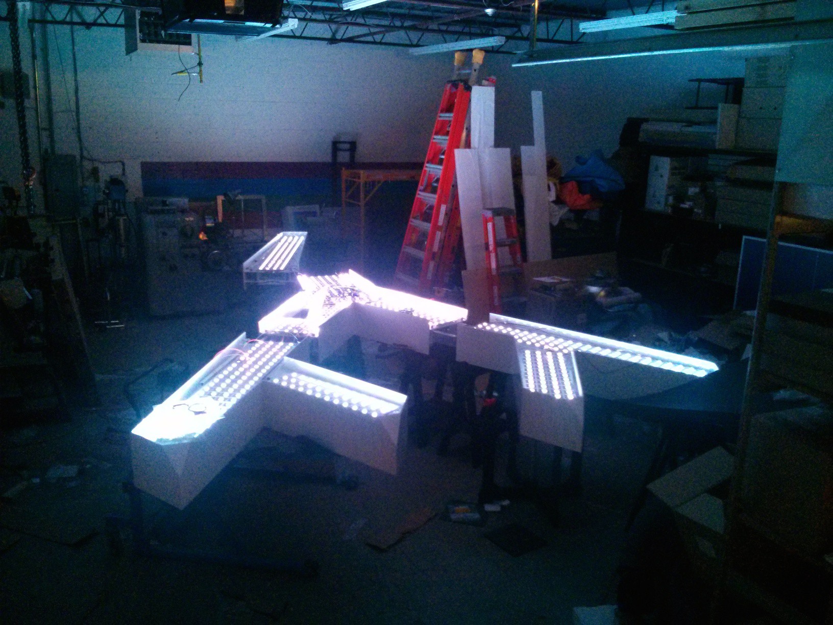
Yet this all was happening just a week before the final install, and so everyone was both excited and concerned as so many details still had to be attended to, such as affixing the LED strips, and mounting the power supplies...let alone finish the fabrication.
In my remaining day and a half at the shop I focused on understanding the addressing of the Sensacells so I could make a big lookup table that associates the NeoPixels to the neighbouring tile.
I also logged any remaining problems, so I could fix them back in Toronto, as there wasn't enough time to do so in Ottawa.
Lastly, I focused on material things, that needed to be done to make it easier for Flux to install my stuff after I left. This included labelling all the LED strips and getting the project boxes together for the controller circuit, and potentiometers.
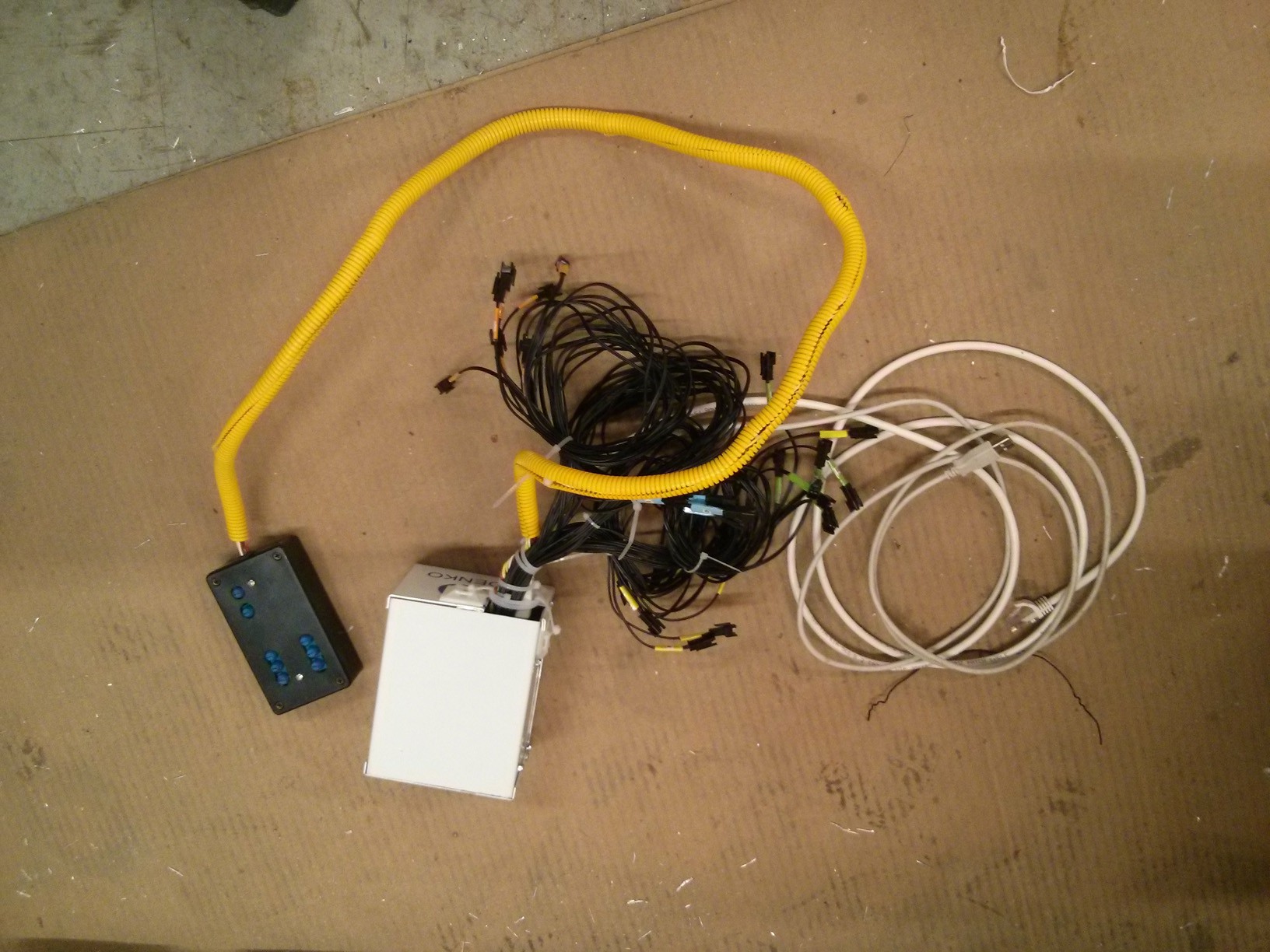
Oh wait, and we had that meeting with the ESA inspector! How could I forget. This guy had the ability to nix just about anything he wanted on the project with a week remaining! We were all nervous, and for my part I was concerned about those non-certified RIGrunners. Steve, a very serious man, came in and looked it over. He picked up parts and took apart one of the RIGrunners. Then he simply said that he could sticker/approve it as signage if we made a few quick fixes. He's the one who required a proper enclosure for the circuits, and a cover for the AC terminals of Power Supply, but that was it for my end. In fact, he was quite interested in the RIGrunners as a solution. I think they could do good business with commercial installations of LED strips if they did get certified (I know it's damned expensive though).
And off I went back to Toronto. The next three days were a flurry of finishing off last minute details such as providing maps for Flux to install my stuff, and attending to bugs in the code. I was pretty much set to go by Saturday morning the day of the install. At 6AM I got a text that the install would be delayed by a few hours because prep work was still being finished, and then again a few hours later, then it was postponed until Sunday morning, and then Sunday at noon. This meant that a two day install (which was short in the first place) was being compressed into less than one day.
I went to the site for noon, and immediately got to work. Much of my gear hadn't been installed. I expected that this might happen, as "filler" LEDs weren't exactly the fabricators priority...and I don't mean that sarcastically. I'd do the same in their circumstance. So I started hooking up my controller to the individual LED strips, and attaching their power connectors.
One of the things that came to my attention just days before was that the two halves of the sculpture would be separated each year. There was no way anyone was going to attach 20 odd connectors across the joint each year, without damaging something, so I used some 15 pin D-Sub connectors to port through all the connections.
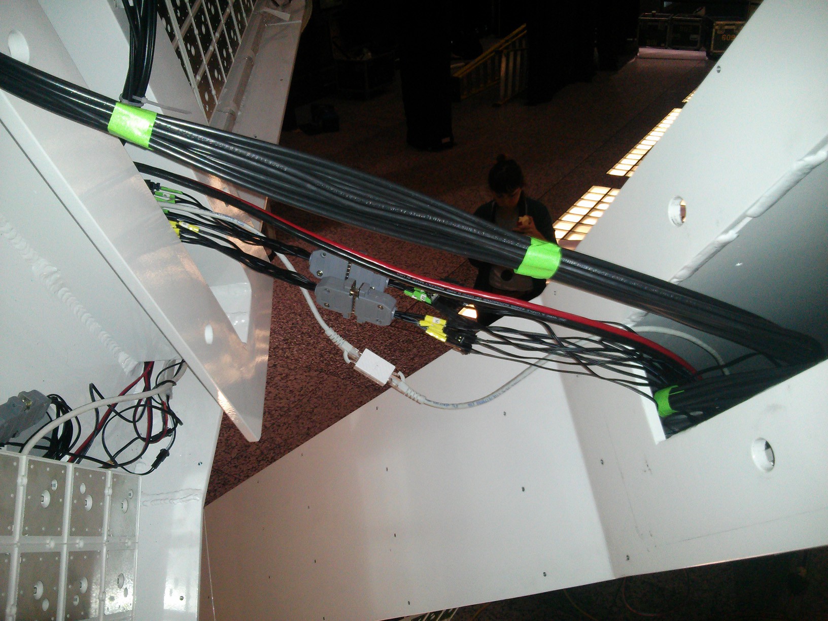
This was all a mad rush, as there was a large crew waiting for these jobs (both mine and others) to be finished so they could assemble the thing. At some points we had to just step aside so they could do their job.
With the sculpture together, we started powering up the sculpture to see what worked and what failed. At first there were flickers and sputters, but with time each...
Read more »I haven't described the sculpture in much detail yet. It consists of two 20 foot "flakes" that are joined at the midsection. Each flake is illuminated on its two faces with Sensacell LED panels, and the filler LED strips. The placement and quantity of strips was determined by the architects, and totalled 70 meters for the entire sculpture.
In lighting tests, we assessed that the 30 LED per meter NeoPixel strips were sufficient, which gives us 2100 NeoPixels to illuminate the whole scupture. On the Adafruit website each Pixel is listed as drawing up to 60mA (for white at max brightness), though in practice I only measured 22mA with my strips using the WS2812B. I believe this is because Adafruit doesn't distinguish between LED type when it specifies NeoPixels, and some other versions of the LED draw higher current. Nonetheless, I wanted to stick to the recommended margins from Adafruit, and to be honest i couldn't decipher the current consumption from the datasheet for the WS2812B.
So 2100 LEDs drawing up to 60mA each at 5V...that's just...126 Amps!!! Holy Crap. I know it's low voltage work, but I hadn't dealt with such high currents before. It was time to call in my electrical guru...Rob Cruickshank. He's a staple of the electronic arts community in Toronto, and used to handle everything electrical at Much Music...which includes large scale lighting shows. Rob's critical advice was more about how to protect myself rather than about electronic design. He suggested that because it is a public sculpture and is drawing high currents that I request the architects to have it electrically certified. This was a great idea. The architects corresponded with the Electrical Safety Authority, who gave us some design guidelines for getting the sculpture approved down the road. We needed to use either Class 2 power supplies, or Class 2 wiring equivalent. This means using UL certified power supply, from which each output is fused at no more than 5 Amps (for 5 Volts). If we could do this then that would make the certification easier. This was a no-brainer for us, as each of our strips drew far less than 5 Amps...perhaps a theoretical 3 Amps at most. But we were going to have many strips, so I needed a way to distribute power to all of them.
Rob had already introduced me to the Anderson Power Pole connectors, which are an amazing high current, low voltage connector. After some more digging I came across the RIGrunner fused power distributors. For $50 to $150 you get a box which takes up to 80 Amp in and breaks it out into as many as 12 lines.
I came up with an artery system, wherein a 5 Volt, 90 Amp MeanWell power supply fed into a couple of RIGrunners in the midsection that then distributed juice to RIGrunners in the other branches of the sculpture, and all of them in turn powered the LED strips in their region. This is nice because the sculpture needs to be reassembled each year and so the crew can just disconnect the main arteries rather than dozens of strips.
My main concern with RIGrunners was that they didn't have any certification, and so it was unclear if they would pass inspection. I should have checked this out in advance before committing, but as the timeline was getting shorter I just went ahead!!
Next on the list was to integrate my work with the software of another project member. This awesome guy was making it such that when you triggered the sculptures sensors, the building's lighting would change as well. His software would be regularly polling the sensors, and my rig would also be listening to the response. We got our stuff integrated without many problems, and showed the section to the Architects who were admittedly confused by all the wiring, but had faith that my plan was sensible, and were encouraged that it mostly worked at this stage.
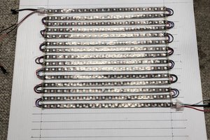
With time a major concern at this point, I quickly fixed up a few software things, and then turned my attention to churning out meter after meter of soldered LED strip...probably about 70 units involving...
Read more »If you prefer videos, go check out the elaborate youtube playlist instead. If you want to jump to the fun stuff, then just scroll to the bottom.
This was a crazy project. When I took it on, I was only going to be building an LED subsystem for others to install. By the time it was done, I was managing most of the lighting in the sculpture. By building the support system, I studied the main Sensacell system more than anyone else, and so had to develop plans for it.
In the beginning, I considered using UEXT modules as building blocks because they had LED strip controllers, and RS-485 modules to link to them, but I looked into Adafruit's NeoPixels and they seemed like they'd do the job admirably. I've become a great fan of Adafruit over the last year because their documentation is incredible, and libraries abundant.
Getting started with NeoPixels was easy. I ordered 5 meters and ran one of the examples. Then, I started addressing each pixel individually. These are nice moments, because you got something up and running to show a client with minimal effort.
Next, I turned my attention to the Sensacells to understand how to communicate with them. They have an API, which is just adequate enough. F-Minus, the architecture firm that hired me, had already chosen this system and had purchased the modules, and so Sensacells were a given. They are actually impressive, and work well for large scale architectural projects. Each Sensacell is a 1' x 1' LED panel with 16 LEDs, and 16 capacitive sensors for detecting bodies. Essentially you wave your hands over top and they change color or pattern depending on how their programmed. They speak to each other and to any peripherals via RS-485. Dozens can be daisy-chained together to cover large surfaces like a wall. I used Processing to talk to them, and started with just changing their colors as a test.
Okay, with that working it was now time to integrate the two sides. This was much more complicated than I expected as the Arduino Uno and Mega that both use 16 Mhz crystals don't speak well at 230400 baud, the rate that Sensacells talk at. After messing with swapping the crystal. I switched to a Due, which worked.
The Due ultimately had it's own problems. For one, it required level shifting the outputs from 3.3V to 5V to get it to work, but also I had some problems which I never solved, because I switched tack first.
Next, I had to test the distances at which NeoPixels that could be run. Critically, this would determine how many strips we could run off one Microcontroller. If they needed to be close then I'd have to disperse many micros throughout the large sculpture. If not then it might be possible to use one...that ended up being the case (although it might have been better to have two; one in each side).
We also found that the same color values used on the Neopixels and Sensacells didn't even nearly match, so I added some pots to control color.
By this time, I was pretty convinced that NeoPixels were the way to go, and had already invested a lot of work into them. In the next log, I'll look at moving to scale.
1. Don't do it...
Create an account to leave a comment. Already have an account? Log In.
Become a member to follow this project and never miss any updates
 Evan
Evan
 Jon Kunkee