To make the experience fit your profile, pick a username and tell us what interests you.
We found and based on your interests.
Well, for the contest that is.
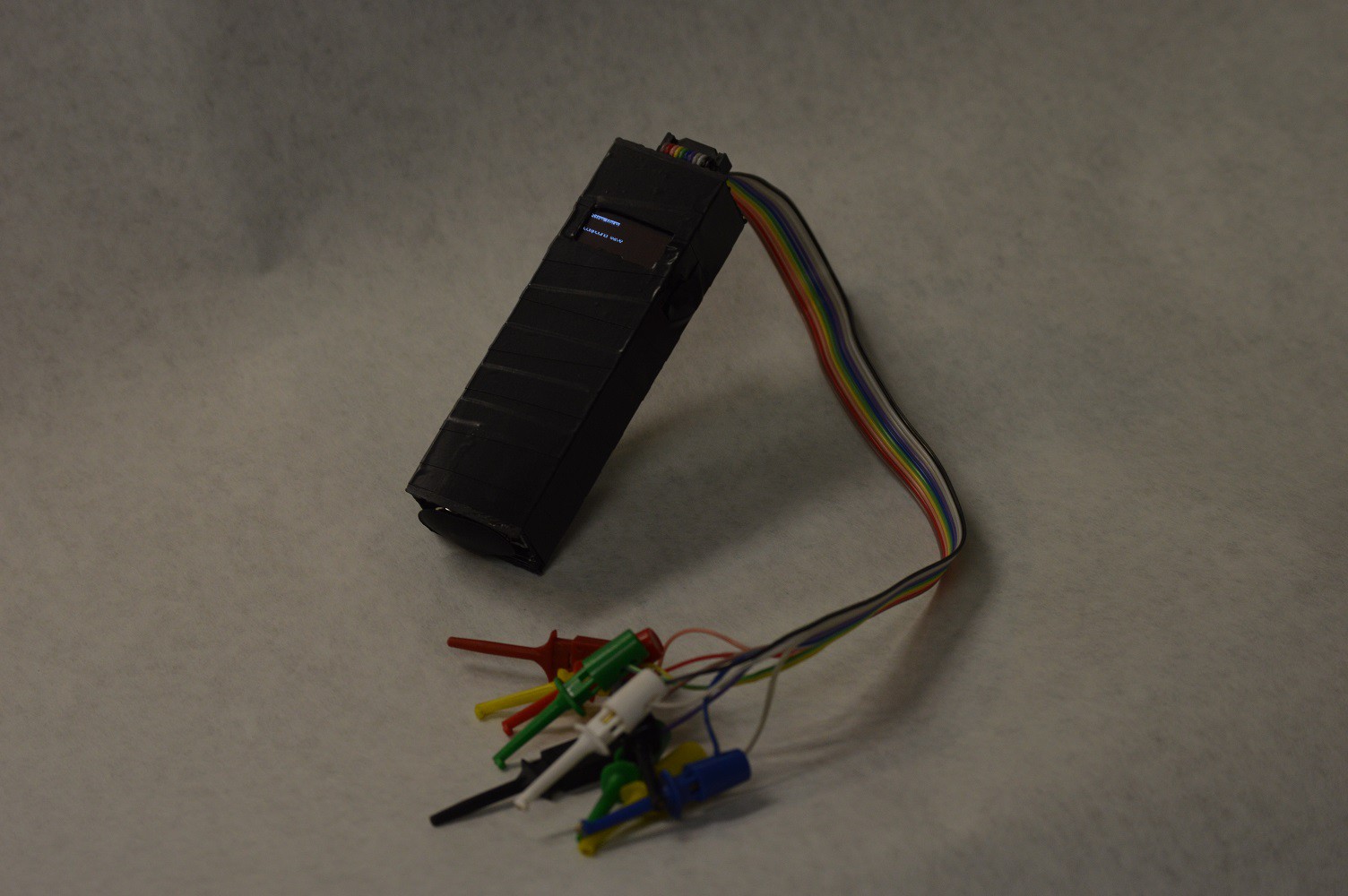
There's many things left on the TODO list for features that are still partially implemented. Not necessarily in the following order:
It's been a fun month working on this on and off. It's been my first electronics project from the ground up for a long time.
With my little eye, an unrouted wire!
At the same time, only ONE unrouted wire. And it's even in a convenient location as I can just use a solder blob to fix it.
But of course that isn't the only issue. The 4 pin connector for the display was rotated 180 degrees and I didn't notice in time... Quick fix of course was to wire it up rather than using a pin header. I just hope none of the wires break off.
I assembled the PCB and attached everything to it last night. I even documented the process a bit with some pictures and video! Well, until my camera battery cut out around half way through the hard part. I'll work on editing those together later.
I tried to get the Trinket Pro working on my computer last night without any luck. It might be the USB cables, or just the computer. I will try with a different computer, but if that fails I'll be slapping my FTDI friend on the Trinket for now.
Pleasantly surprised with my first run through OSH park. I payed less than $13 for these boards, and a lot of that was shipping to get them here even one day sooner. I should have finalized the PCB design earlier, now I only have a few days left to assemble the prototype and get the firmware working! If there's an error in the PCB design things are going to get a bit interesting...

I should have cleaned up the schematic and released it over the holidays. Now even more things to do.
Every project needs a case! Currently I have a rectangular case designed around the parts using OpenSCAD. The top and bottom are open to allow fitting parts in for testing.
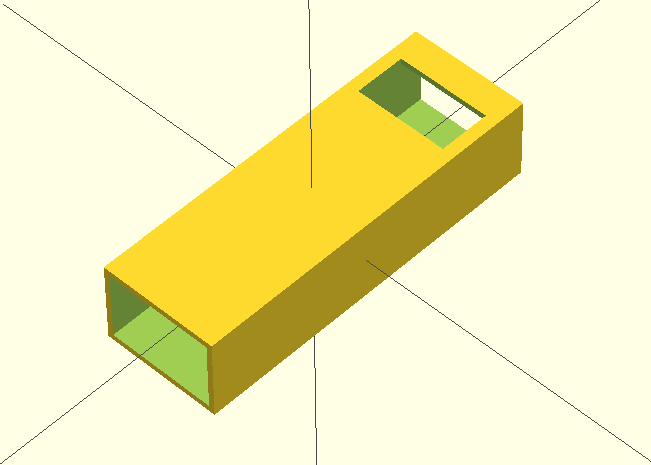
I haven't done much on the firmware side while I have been waiting for the PCB to come in, but I should replicate the PCB on a bread board and test everything out. Need to hunt down friends with an oscilloscope to look at the output at all though... Well, the output frequency should be low enough that I should be able to use a sound card and a computer to look at the signal. We'll see.
In the event that the PCB doesn't arrive in time I'll have to wire everything up on some perfboard. I hope the PCB arrives with some time to spare!
After finally settling on what the system needs I put together a quick schematic and board in Eagle. This is far from my best work, but I was in a hurry to get it out to OSHPark because of the turn around time. In the event that the PCB doesn't come in with enough time to spare I suppose I'll just have to deadbug everything! ;)
This PCB should allow me to fit everything into a case that is 30mm wide, 100mm tall, and 20mm thick.
Without further ado, here's a bit of an overview of the PCB.
On the top I will be mounting the output port, the I2C OLED screen, 2 pullup resistors, and rotary encoder. I chose the 2x5 IDC connector for the output port because I just happened to buy a bus pirate and can reuse the clip leads that I bought with it. The outputs are as follows.
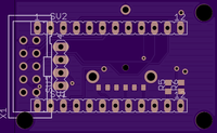
On the bottom I have 2 low pass filters and a quad op amp. The Trinket Pro will also be on this side. I designed the filters using a Sallen Key filter design tool that my friend made. He will eventually make this public once he cleans it up, but it is pretty easy to use as long as you know a bit of python currently.
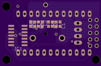
As you may have noticed I have been prototyping my system on an Arduino Pro Mini rather than a Trinket Pro so far.
Although the system is the same on many levels there are a few distinct differences that need to be accounted for.
Number 2 is the big one I didn't take into account so far in my code. I use an interrupt for reading the rotary encoder and another for reading a button press. After I realized this I was worried that I would need to start continually polling the inputs in a loop rather than using the external interrupts, but I have been saved!
It ends up you can set up an interrupt on any of the IO ports of the microcontroller. This means I can hook up all my inputs to a single port, interrupt on any change to that port, and then actually read each of the inputs to see what happened. More information on how to set up this type of interrupt is available at http://www.geertlangereis.nl/Electronics/Pin_Change_Interrupts/PinChange_en.html
I got my 0.96" OLED display in today to play with after work. After wiring it up into my test setup I attempted to draw an image of a sine wave only to find some odd results...
Easily enough fixed though after realizing I had packed the bytes incorrectly. Now to see if I can fit the OLED code along with the waveform code into the Trinket Pro...
I'm hoping that I can. If so I will use the OLED screen and a single rotary encoder / push button combo unit as the input to the device. Unfortunately none of the ports on the Trinket pro are fully available, so if I want to use an r2r2 dac I would need to write my bytes to multiple ports...
There are two main methods of creating an analog waveform using a digital one. Due to various limitations of the Trinket Pro hardware the pros/cons are listed below.
Given enough time I plan on using a mix of both methods 1 and 2, where I have a single high speed output line and multiple low speed outputs.
While waiting for parts to arrive I've decided to work a bit on the software side of things.
Well, not actually the software that will run on the Trinket Pro, but some software to help predict what kind of results I can expect from the actual hardware once I get it all set up.
The software currently generates a sine wave target, creates the PWM signal that will feed into the low pass filter, and displays everything in a neat little window. The "Scale" bar actually adjusts the PWM frequency. Not surprising, but this frequency can't be too close to your sine wave frequency or you won't get good results.
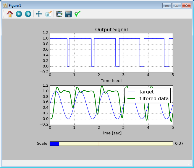
Other wave forms should be simpler to create, especially digital ones.
So far I've been looking at various things. I've started with the following 3 steps/questions.
1) What do I actually want the device to do?
2) How should the user interface be set up?
3) Spec parts
As usual, answers to these questions just brings more questions.
1) Should the device generate a single waveform, or multiple waveforms? This changes the type of DAC that I will need to create.
2) There's only 28kB of space on the trinket. A complex UI using something like an OLED screen will most likely not fit on top of the waveform code. Let's go with buttons, people like lots of buttons, right?? Especially with no visual feedback...
3) It ends up that in all actuality I found myself trying to spec the parts to fit my interface most of all. That's when I realized things might not be as easy as I hoped as one crucial part eludes me.
In the mean time I have parts on order for fleshing out a prototype. Once I have a reasonable prototype worked out I can get back to worrying about the end product. Current system model is as follows, nothing too complex.
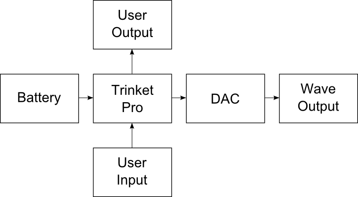
The system should be pretty easy to set up with alternative components on a protoboard in the event that you don't want to make a PCB.
For information on the initial software setup for flashing the Trinket Pro refer to the Adafruit guide at https://learn.adafruit.com/introducing-pro-trinket/overview
The schematic is not the cleanest I've made, but I was in a hurry to get the board files out the door to get everything ready on time.
The low pass filters are set up in a Sallen-Key topology with the following components:
The OLED data lines use 4k7 Ohm pullup resistors that are installed at R6 and R7 on the PCB. The OLED screen connector is rotated 180 degrees in the first PCB design file. This needs to be fixed in the future, but for now it is easy to fix in wiring.
The video doesn't have audio, but there are subtitles. Didn't have time to make a decent recording of the audio dub :/
Create an account to leave a comment. Already have an account? Log In.
Become a member to follow this project and never miss any updates
 Applied Procrastination
 Michael O'Brien
 Matias N.
Add in a pattern generator for a video monitor. e.g. cross-hatch pattern for VGA,
I'm not sure if it is do-able.