Close
0%
0%

Insulin Minder

Helps keep track of how hot or cold my insulin has gotten and when I last had an injection. Great for the absent minded diabetic!

Similar projects worth following

As a type-1 diabetic, I am dependant on regular injections of insulin (in my case, two different types) - four or more times a day. This means carrying my insulin around with me pretty much everywhere. Generally insulin is kept refrigerated, but the vial in current use can generally be kept out of the fridge for a week or two without any problems - UNLESS it gets too hot.

This is where the minder comes it; it will ideally be a small device which stays with the insulin (possibly even integrated into its case). It will keep an eye on the temperature extremes reached and let me know if it ever strays outside a given range.

As added value items there are a few stretch goals that it should be able to deliver:

  • Let me know what the minimum and maximum temperatures where since the given vial of insulin was started.
  • Be able to report temperature over time, so I can identify places and times to avoid leaving my insulin in the future.
  • Be able to report battery status.
  • Let me know when I last had my insulin.
  • Let me know how much insulin I last had.

Other general goals for the project include:

  • Be small.
  • Be rechargeable.
  • Last a long time without recharging.
  • Effortless to use for main function.
  • Quick to use for value-added functions.
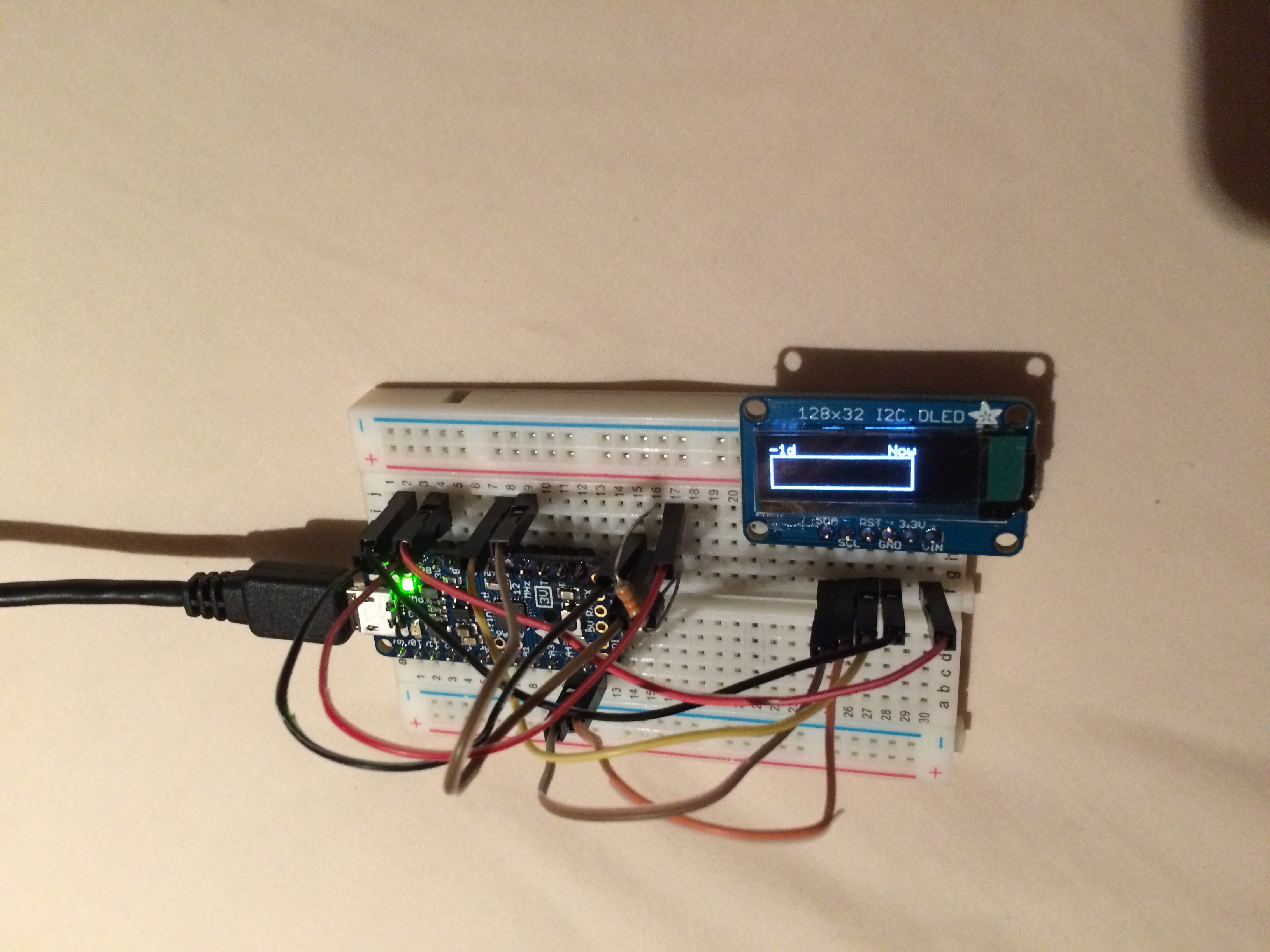
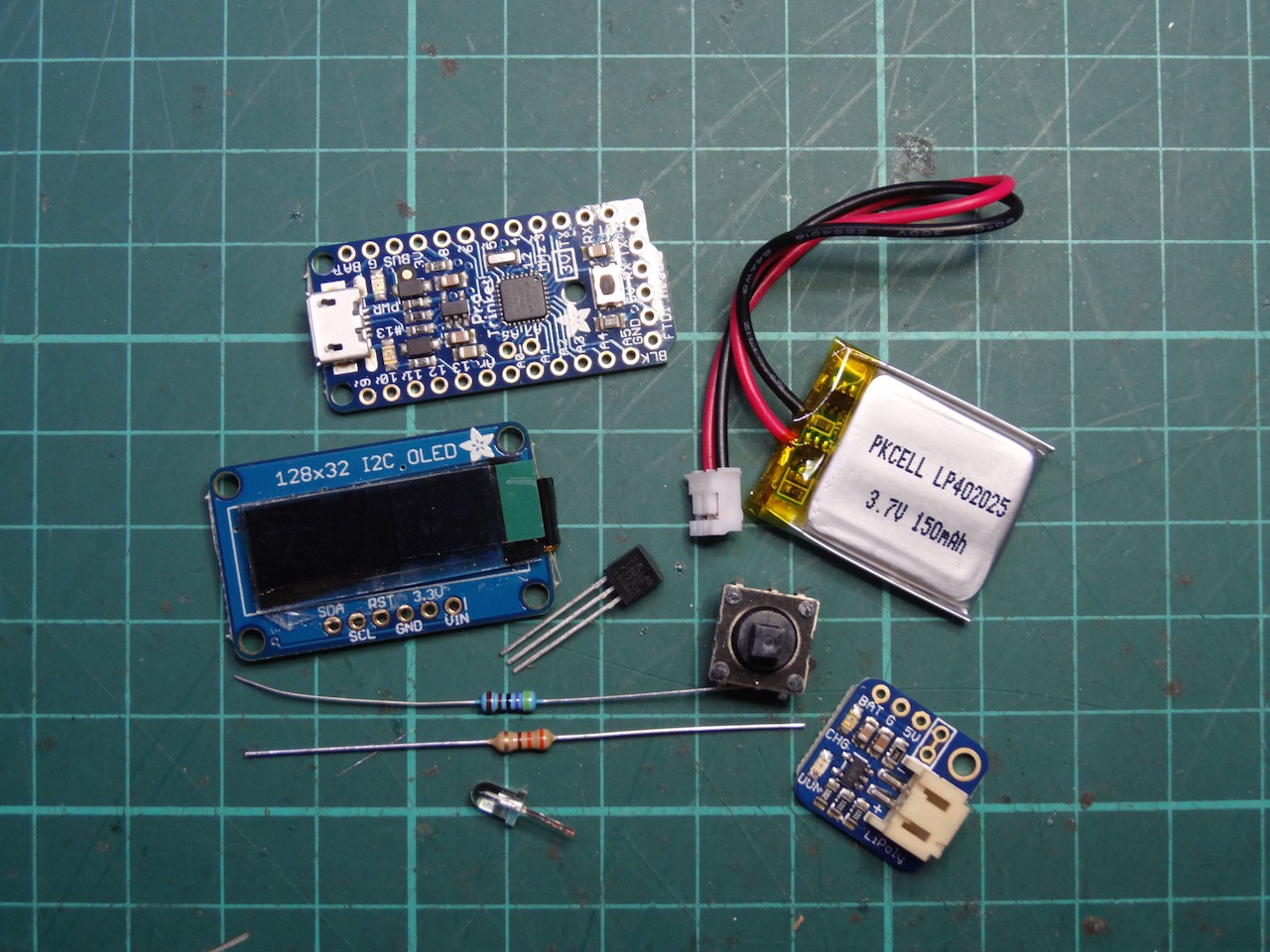
  • 1 × Trinket Pro 3.3V Adafruit #2010
  • 1 × Monochrome 128x32 I2C OLED Display Adafruit #931
  • 1 × DS18B20 Digital Temperature Sensor Adafruit #374
  • 1 × 5-way Navigation Switch Adafruit #504
  • 1 × Trinket Pro LiIon/LiPoly Backpack Add-On Adafruit #2124

View all 6 components

  • Mk2 Ahead

    Linus Dillon05/25/2015 at 00:19 0 comments

    It looks like the power problem is now sorted following the fix I mentioned in my last log. I'm now getting about a month per charge, and if I dropped the low-battery threshold to 3.2V I could probably go two. Better than I'd hoped!

    I'm now working on the Mk2 which will use a custom PCB and no off-the-shelf modules. It will feature an actual battery cut-off when the low-power threshold is reached so the LiPo will not be damaged. The idea is that a FET is in-line with the battery. When plugged into USB, the FET is held on. The micro-controller can also drive the FET, and will hold it on as long as it detects the battery is OK. When the battery drops below the threshold the micro-controller will allow the FET to turn off. That of course also kills power to the micro-controller, so the only way of waking things up again is to plug it in to charge. Should work.

    I have the bare OLED displays via EBay (i.e. not on a breakout/carrier board) and will need to now add the supporting circuitry myself. I think with all this I should get the thickness down under 10mm (display + PCB + battery). I'm currently trying to use bits from the seedstudio OPL so I can use their fusion service, although soldering the SMD stuff is no longer as intimidating as it was.

    I'm considering making these generally available (with the addition of some breakout points for unused pins) as a small "wearable" board with OLED, battery, charging circuit and micro-controller seems it may be of interest to others, and this is a different form factor to most I've seen which seem to favour larger colour and/or squarish displays.

  • Power improvement

    Linus Dillon03/22/2015 at 11:07 0 comments

    Found one of the causes of the excess power consumption; the ADC. It seems to get the greatest benefits form sleep mode, you need to explicitly disable the ADC before sleep and (if needed) re-enable it on wake. This does not get disabled with the other on-chip peripherals. Anyway, I've committed the change to the repo (https://github.com/LinusDilon/Insulin-Minder). After a week running with the change the battery has dropped maybe half way. I think I'll get at least two weeks, and maybe as much as four out of it now.

    An another note, I'm starting to look at whats needed to builds one from scratch using a custom PCB.

  • Complete... until the next one

    Linus Dillon02/18/2015 at 11:24 0 comments

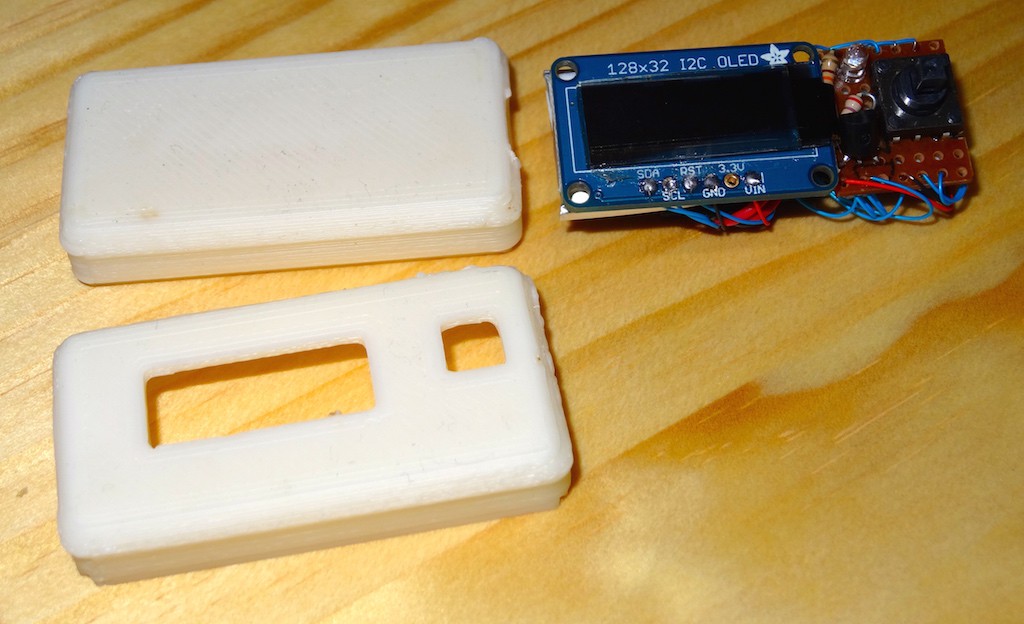
    Finally finished the Insulin Minder (well, Mark 1 - see end of log). After soldering the bits together, I have added some double sided tape to keep it all together and add a little solidity. I then designed a case for it in OpenSCAD and printed it out in ABS. It didn't print perfectly (the nice curved edges on the back and front ended up quite blobby - my printer does not yet have a filament cooling fan, so I think the overhang presented it with difficulty).

    I have actually been travelling for a week away, and had a chance to use it properly. It came in handy one night when I had doubts about the bar fridge I had my insulin in; it seemed unusually cold for these and I wanted to make sure it wasn't getting down to zero. After a night in the fridge the Insulin Minder was able to confirm it only dropped to a nice safe 4 degrees centigrade. Another day I spent some time in the engine room and the boiler room on an old steam tug (love steam engines). Despite 45 plus temperatures, the interior of my bag never got over 31. Nice having the certainly around it.

    More coding to be done of course (add the histogram in, make use of the alert LED, injection site tracking) but the main functionality is complete. There is still the battery life issue - I hope to mock up an ATMega on a breadboard this weekend and get to the bottom of that. Finally the main issue is size - using off the shelf parts it has ended up being three PCBs sandwiched together along with the LiPoly battery.

    So, if I can solve the battery life issue, I think I will have a go at a Mark 2 by making custom PCB incorporating the ATMega, the battery charge circuitry and support circuitry for the OLED display. I may also move to three or four SMD tactile switches rather than the navigation switch (which is nice but a bit bulky). Thats all a level of integration and detail I have not really delved into much before, let alone significant SMD work.

    I am thinking of milling my first prototype board here and hand soldering my first prototype using my hot-air rework station and solder paste. If it works I may even look at doing a little run of them via SeedStudio or similar and putting them up on Tindie. Any thoughts anyone?

  • Assembly

    Linus Dillon01/18/2015 at 11:51 0 comments

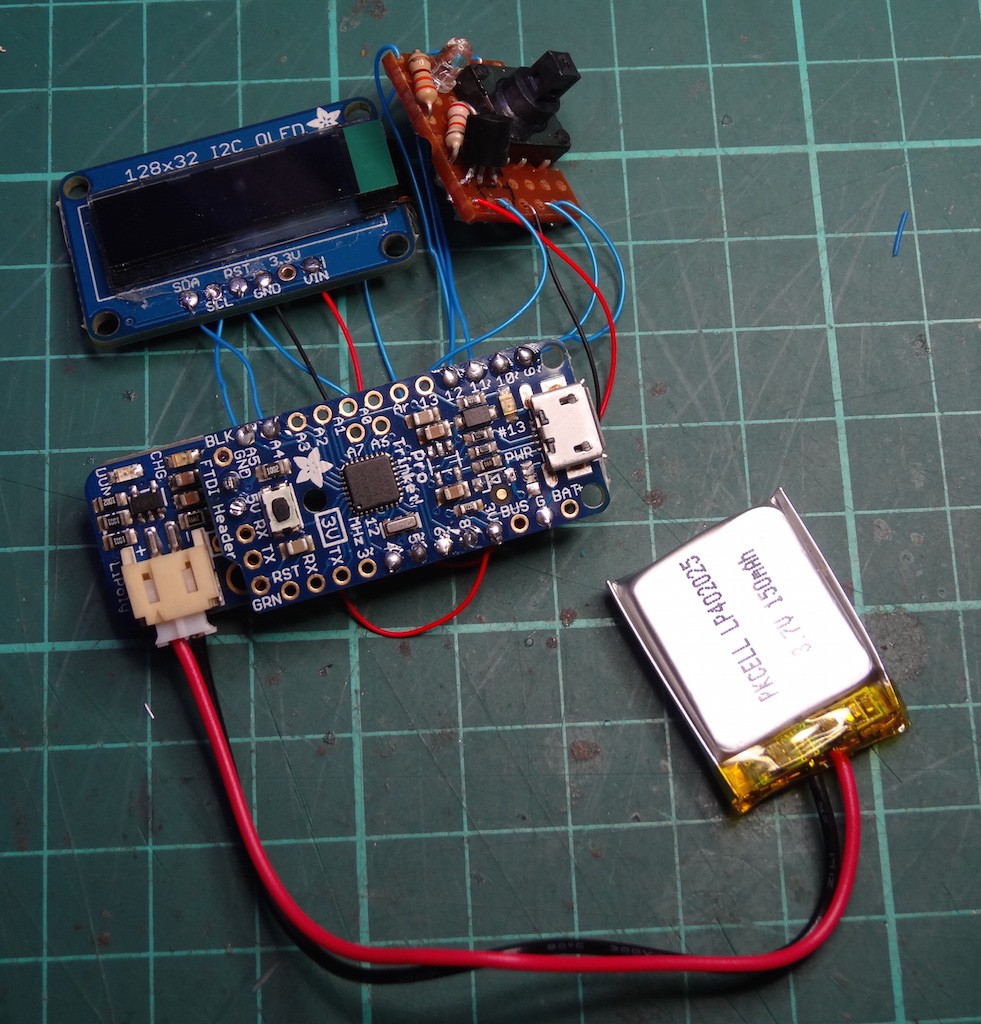
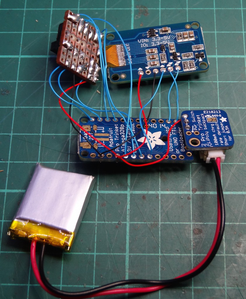
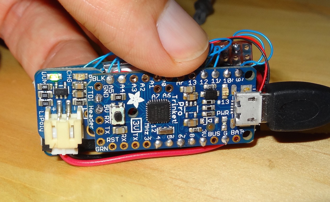
    I finally got around to assembling the first non-breadboard version of the minder. In order to keep size down without a custom PCB I used a kind of dead-bug style of assembly, along with an alternate mounting arrangement for the LiPoly backpack. Anyway, pictures!

    Parts

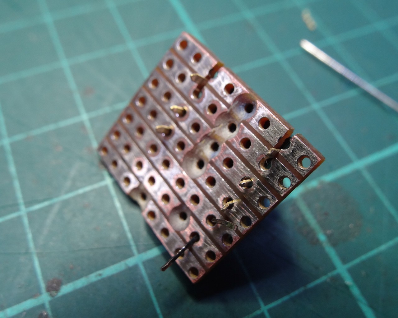
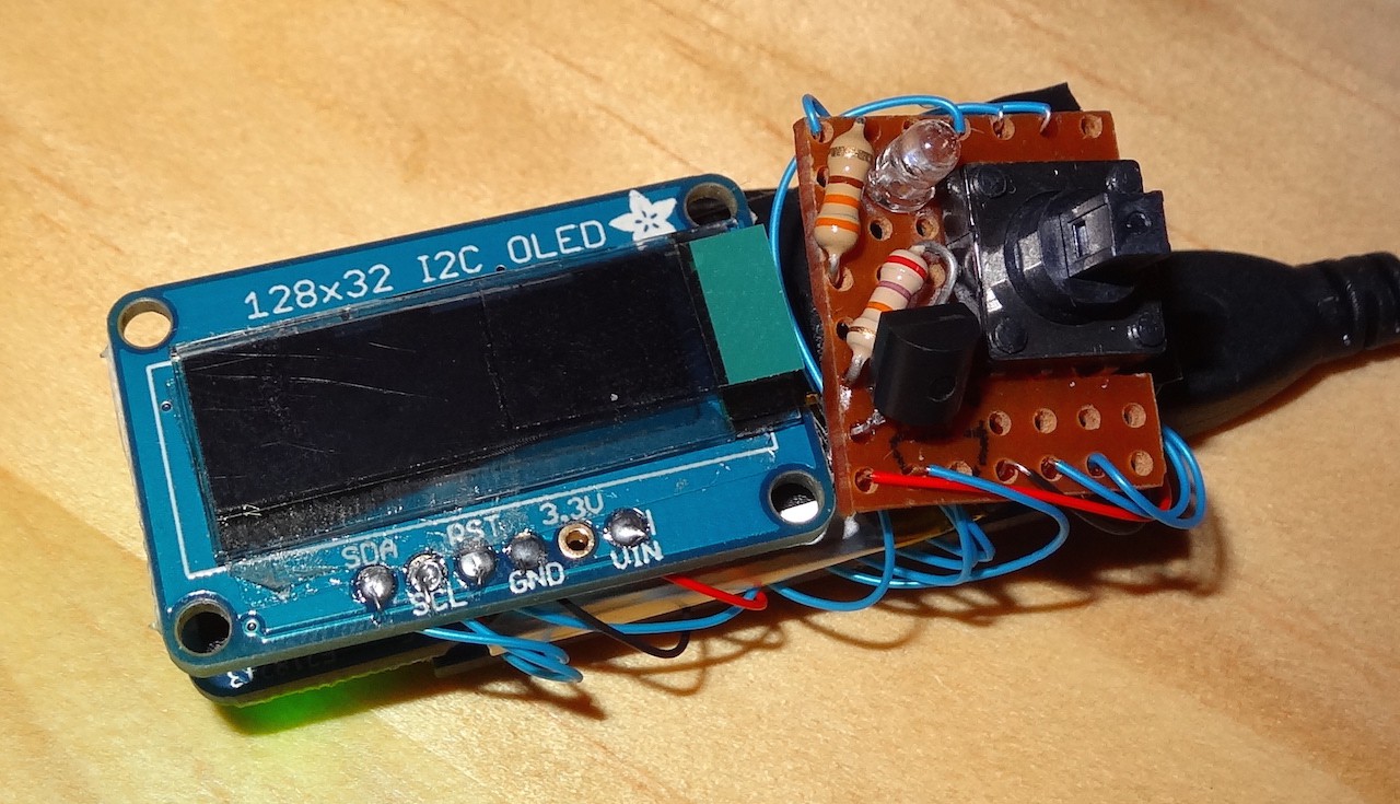
    I used a small piece of strip board to host the discrete components (nav switch, temperature sensor, resistors and LED). The LED and its resister are new; I thought some indicator I could use to draw attention when an alarm condition occurs would be a good idea.

    I used the BUS and GND pads at the Trinket's FTDI connector to attach the LiPoly backpack. This makes better use space for my application. A separate wire then runs from the backpack to the 3.3V pad on the Trinket.

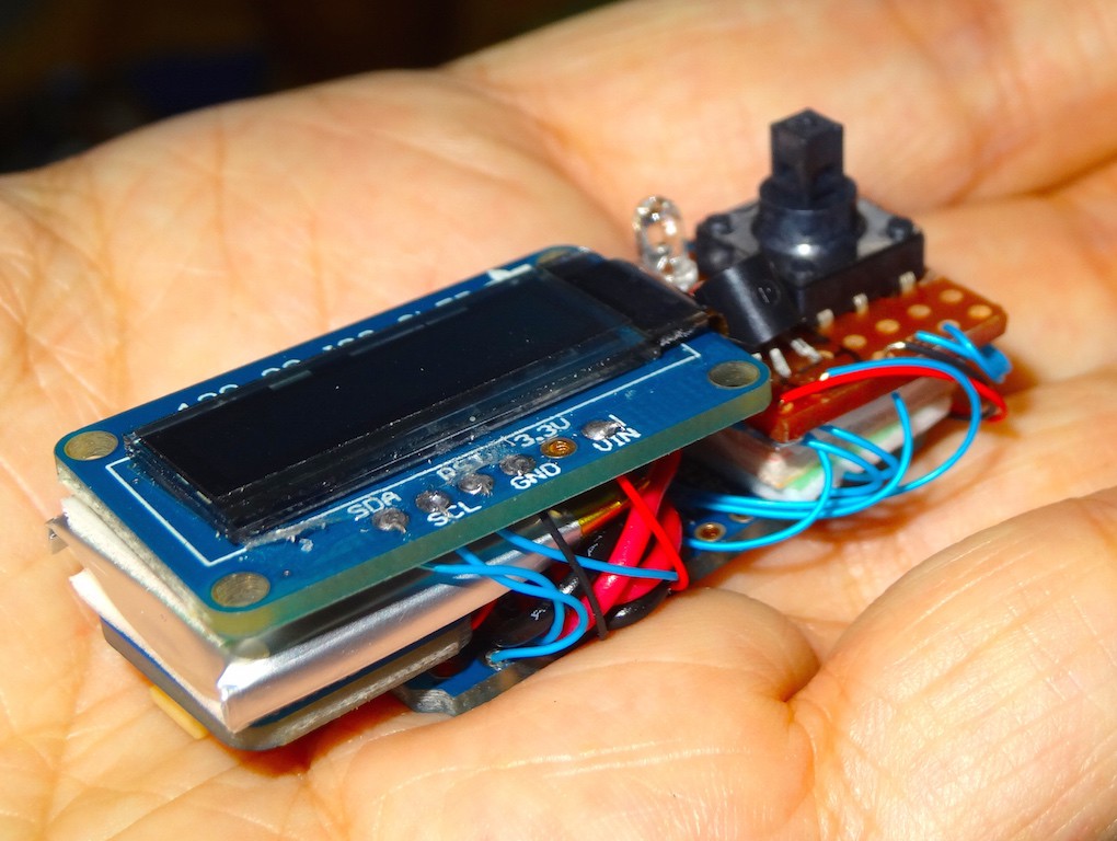
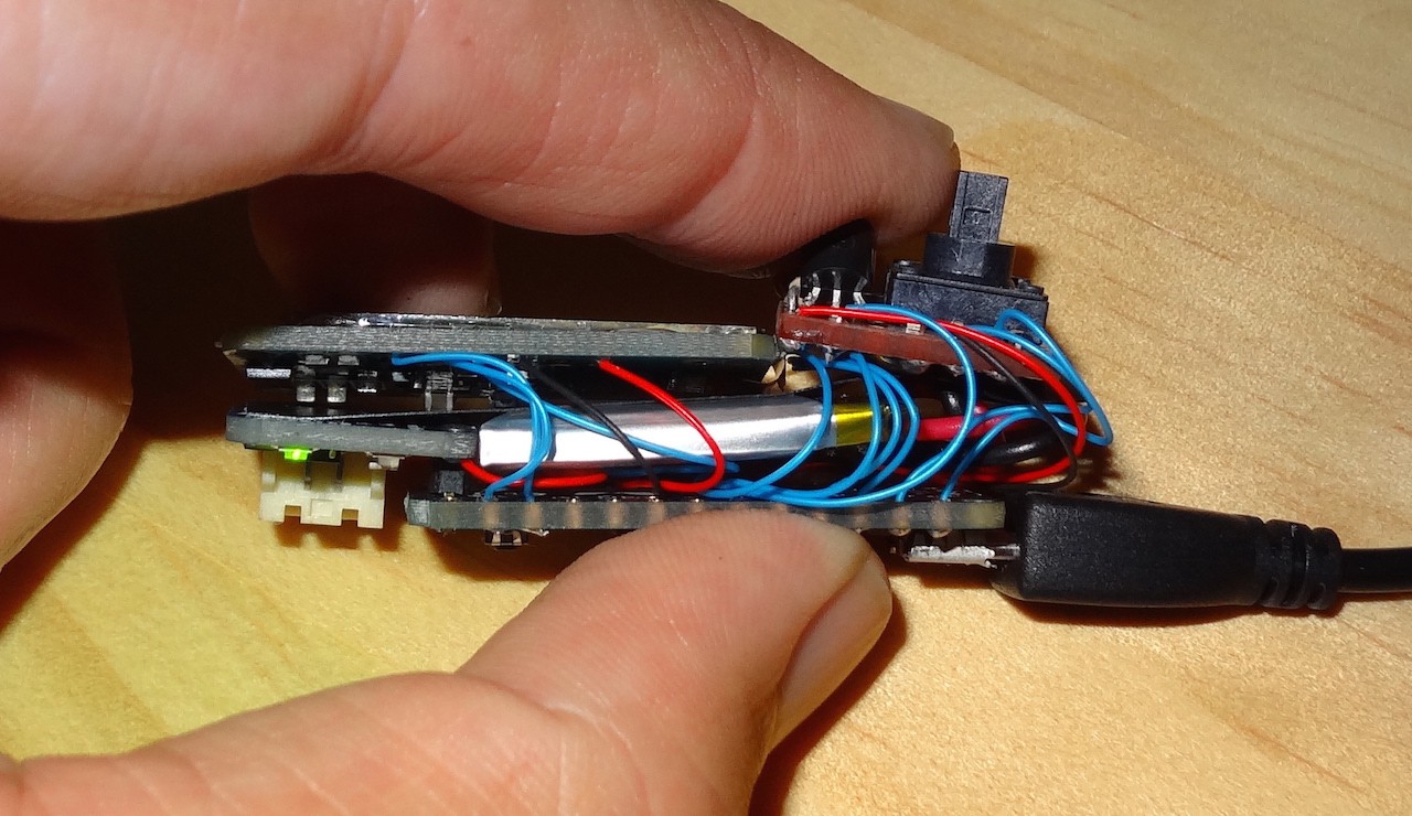
    After mounting the backpack I ended up with 4 distinct bits; the Trinket+backpack, the OLED, the discrete carrier board and the battery. I connected the first three together using fly leads of wire-wrap wire. I quite like this stuff; very thin, surprisingly forgiving of being flexed, and stiff enough to hold a shape. I assembled it flat out, arrange so I could fold the front parts (OLED and discrete board) over, with the battery sandwiched between the front and back (the trinket and LiPo backpack).

    Overall it ended up being surprisingly small for a device I hadn't built a custom board for. Of course a case is still needed; I might be able to get away with some clear heat shrink, or I'll have a go at getting my 3D printer working long enough to do a proper case.

    I'm now trying to decide if I want to take this further. There are two problems with it at the moment:

    1. I still haven't been able to get the power use down any further, even though a bare ATmega328 should be able to go down to uA, not just mA. Based on the battery levels reported on my breadboard version, I think battery life at the moment is around 2 weeks (a little higher than calculations would suggest, but I may be being a little cautious regarding the minimum level for the battery - I have the battery low at 3.8V at the moment).
    2. Its still larger than I'd like.
    To go further though I'll have to design and assemble a custom PCB using surface mount components. Not something I've done before. A first step though would be to modify my breadboard layout to use a bare ATmega328 and confirm that the power usage drops to what I was expecting.

  • Battery Gauge

    Linus Dillon01/13/2015 at 12:41 0 comments

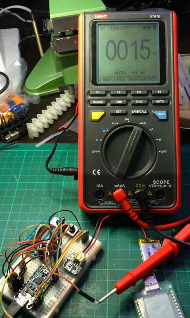
    Small bit of progress. After the solder rework station turned up I set about desoldering the regulator and one of the Schottky diodes (MUCH easier this time around). However this has still not reduced the power consumption below 0.15mA. I have one more idea to try before just accepting the 40 day or so battery life.

    I am now however happy to run everything off the battery, so the project is at least mobile now (albeit still on a breadboard).

    I've also spent a bit more time on the software. The ability to log fresh insulin (and hence clear the min/max temperatures) is in, along with a battery gauge page (although I'd like to add a small battery indicator to the default page too).

    I'll post pictures or a video when I can. Git repository has been updated.

  • Software + Font (plus new toys)

    Linus Dillon01/06/2015 at 11:32 0 comments

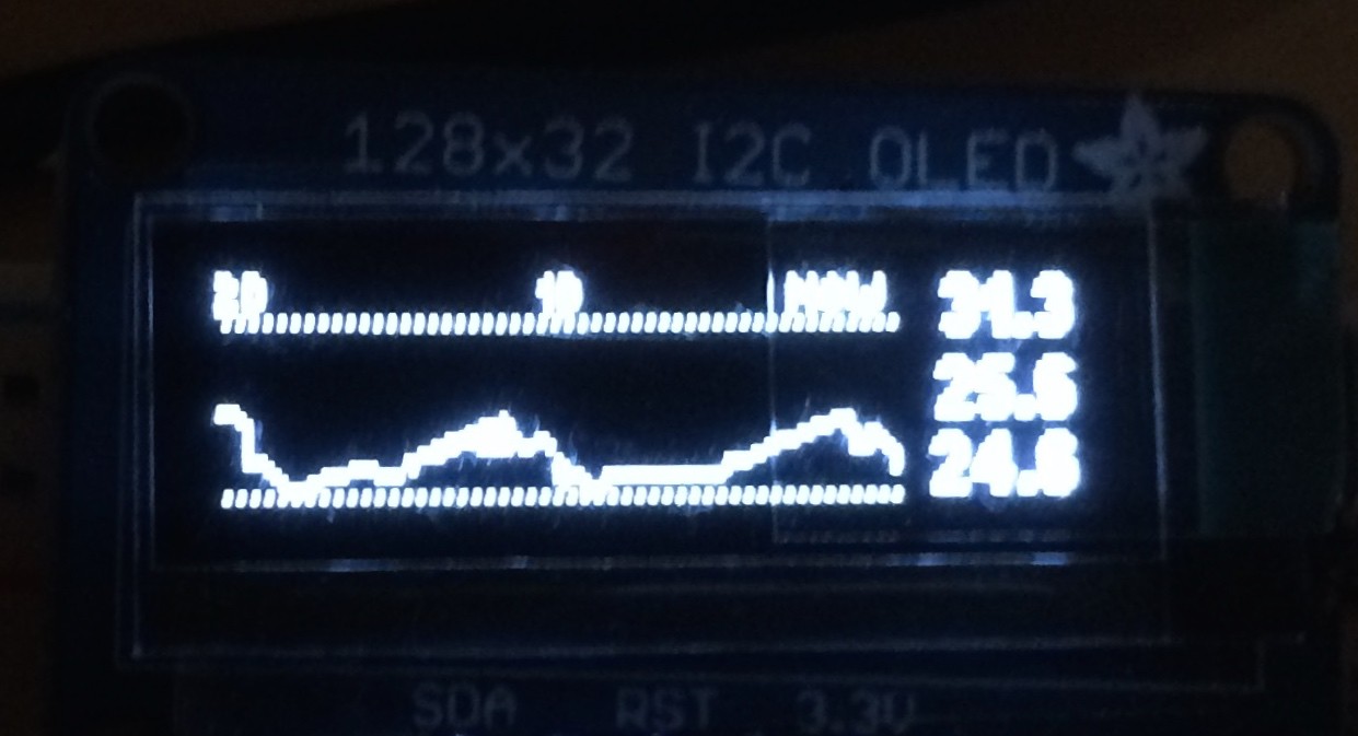
    Lots of progress on the software front (see my git repository). I've now got the main screen working, complete with history graph, alarm set-point indicators and min/max/current temperature readouts (sorry about the poor photos):

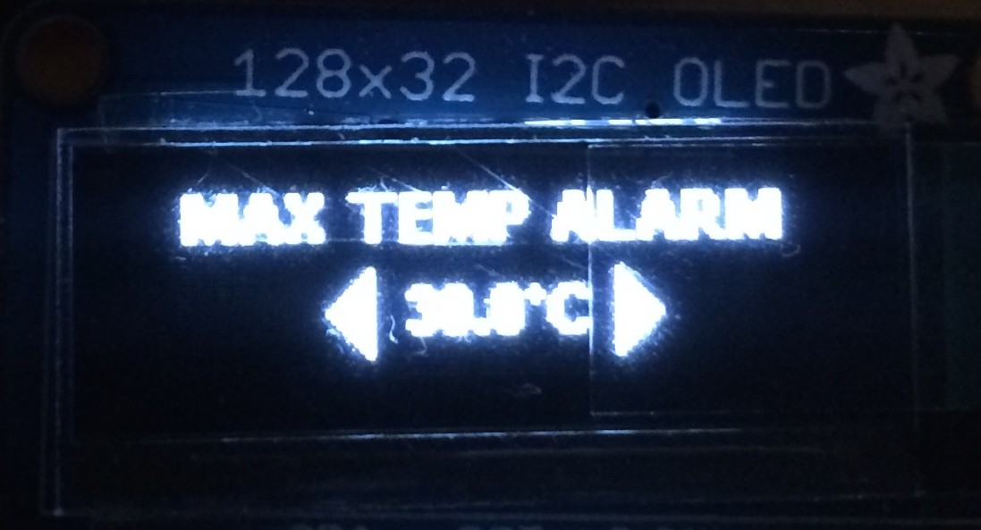
    I also have the screens for setting the min and max temperature alarms:

    Hard to see on the first screen, but I also added an additional font - smaller than even the default one in the Adafruit library.

    As for new toys, my solder rework station (an unbranded 898D+) arrived, as has a few extra parts for the Insulin Minder. Hoping to get some of the hardware sorted this weekend, at least to the point of being able to carry it around.

  • Program Core & Contest

    Linus Dillon01/03/2015 at 08:02 0 comments

    After the setback from last weekend, I'm still waiting for new parts (additional LiPo backpack) and tools (cheap solder rework station) to arrive before jumping back into hardware. But I have made significant progress on the software side.

    First up, here is a short video showing the project and where the software is at:

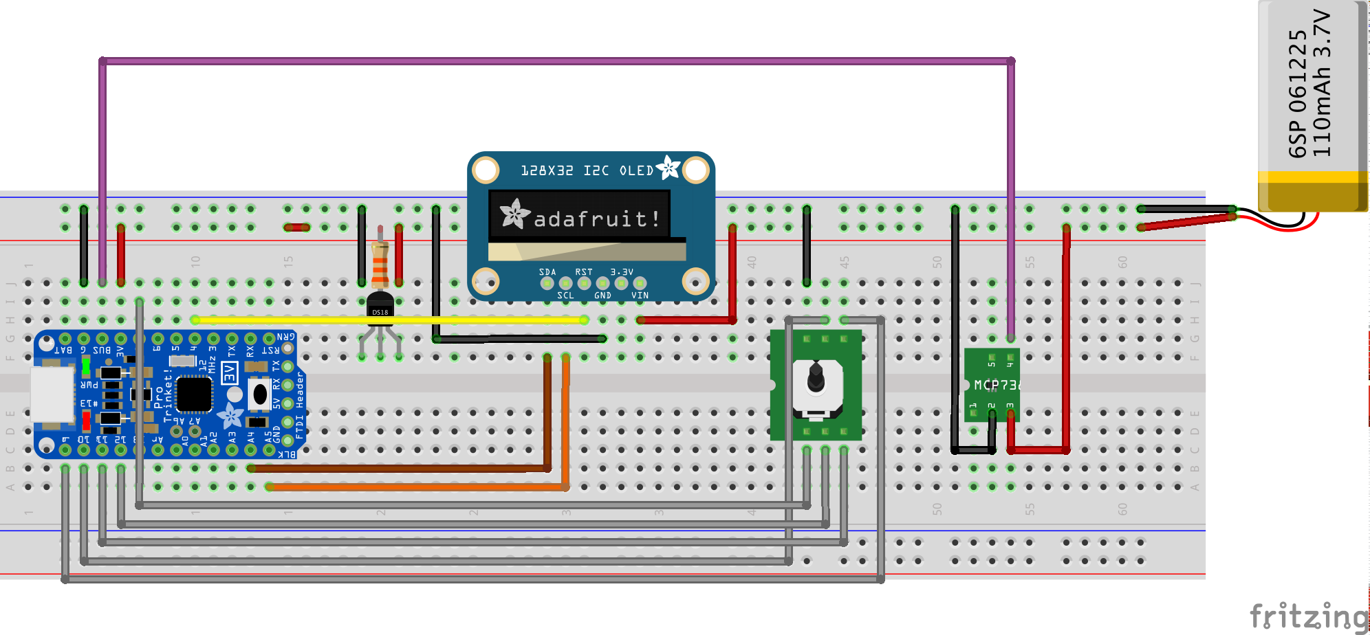
    Also, here is a schematic I put together in frizzing (thought I'd give it a go - a bit limited when the exact part your after isn't there however). Note that rather than the LiPo Backpack I have used a basic breakout board for the charger chip as thats all I could find for Fritzing - should be reasonably straightforward to switch in the proper Lipo backpack however:

    So, progress. The main application loop is now working, complete with periodic wake to record temperature in EEPROM, wake up when you move the nav stick, the bare bones of the home (temperature history) screen along with placeholders for the other initial ones I'll have, handling for moving from one screen to another, button/nav stick handling (including debounce and renounce), auto-sleep after 10 seconds inactivity, and places to insert the alarm checks and notifications. What remains is pretty much just filling in the specific screens. All updates pushed up to git once more.

    One other little change of note is I modified the temperature reading code; previously it was throwing away the fractional portion. I'm now keeping it all and showing the temperature to a one decimal place - nice to watch it bounce up and down in response to a touch or drafts. The conversion of the 12 bit Celsius value to a value for display is handled by two (possibly to be combined) functions, so if anyone wants to add support for weird non-metric units (e.g. Rankine, Fahrenheit, Gas Mark) it would be easy enough to modify it there. Everywhere else I expect to just be showing relative values, so the specific scale won't matter.

    Clearly I'm some way away from this being complete; final assembly of the circuit, completing the software and a case. Hoping to have it complete and documented within two weeks however.

  • Setbacks and font stuff

    Linus Dillon12/31/2014 at 00:29 0 comments

    Had a go at putting together an assembled version of the minder. My plan was to sandwich the battery, LiPo backpack and temperature sensor between the Trinket and the OLED, with the navigation button to the side of the display. All of it would be wired together using fine wires (wire-wrap wire in fact) so that I don't have another layer of PCB bulking it out. All a bit fiddly and I ended up not getting very far. To make it thinner still I tried to desolder the JST connector on the LiPo backpack and solder the battery leads directly to it (maybe not the best idea, but those JST connectors are fairly thick compared to all the other components). Instead I managed to kill the LiPo backback by lifting tracks on the PCB.

    As a result I have (i) ordered some additional LiPo backpacks and (ii) am rethinking my approach to packaging of at least the first unit and (iii) have ordered a cheap hot-air rework station from EBay (have wanted one for a while anyway). I might just go with the "natural" method of mounting the LiPo backpack on top of the trinket as intended (other than the output from the backpack to the Trinket). I'll end up with a much fatter minder, but there will be less risk of it not working too. Note for Adafruit: how about a fairly bare-bones breakout board for that charger chip? One with no JST connector...

    As I'm waiting on bits to arrive before jumping into hardware again I have instead done a little software work. As usual rather than trying to take the shortest path to having something working I'm adding bells-and-whistles. In this case support for better fonts on the OLED. To that end I have grabbed a nice small true-type free-for-personal-use font (Bit Daylong 11), converted it to C code (I found a Windows application to do this), and have written a function to print the characters (yeat to be tested, but all pushed to GitHub).

  • More power savings

    Linus Dillon12/21/2014 at 08:26 0 comments

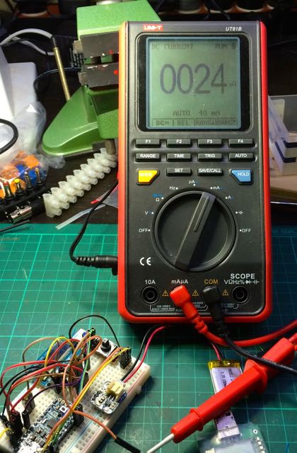
    As I said in the last log, with the Insulin Minder consuming 3.3mA in when in sleep mode the battery won't last long enough for it to be useful - less than two days. The obvious culprit was the power LED, so today I desoldered it and measured the current again.

    Down to 0.25mA, or about 25 days. Much better, but still a lot more than the bare ATmega328. In this configuration, the battery is being fed into the BAT pin on the Trinket, which then takes it through a regulator. Given this will only ever be powered off a single LiPo battery, there is no risk of ever exceeding the 5V, so this is a bit pointless. So I tried feeding it in directly into the 3.3V pin instead:

    Even better. Down to 0.15mA or around 41 days. I know it is possible to go even further here. I don't THINK that the display or temperature sensor are responsible (I tried disconnecting them and the power draw remained about the same). I suspect that either there is still power being lost through the regulator (even though I am feeding power in only on the "out" side), I'm missing something with the Trinket Pro's circuitry or I'm loosing power through some of the input or output pins. Still, 40 days is good enough for now.

    Towards making this a practical device, I need some way of knowing when the battery needs to be charged. This is actually quite easy now that the Trinket is directly powered off the battery, as I can use the internal voltage reference to get the battery voltage. I found this code at https://code.google.com/p/tinkerit/wiki/SecretVoltmeter.

    The final bit of code I worked on today was a small change to keep track of time. When in sleep mode the normal timers are not running. The only source of time available is the watchdog timer, but that has a few issues; (i) it can't be read directly - it only triggers an interrupt when done (ii) it is not perfectly accurate. For my purposes I don't care too much about accuracy - for simplicity of implementation and use the Minder won't keep clock time, but instead just log readings over a 24 or 48 hour period - if that ends up being 10 minutes long or short it doesn't much matter. As for not being able to read it directly, I have addressed that by manually adding the configured watchdog period to a timer variable each time the timer is triggered. This works even if the Trinket has already been woken up by the navigation button.

    So, that leaves me with a pretty much complete circuit! Running off battery, monitoring temperature and battery voltage, keeping track of time and able to wake up when the user uses the navigation switch and able to be recharged when plugged into USB. Now I just need to package it up and finish the software.

  • Power... down?

    Linus Dillon12/11/2014 at 12:20 0 comments

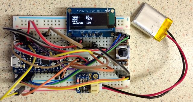
    After a bit of a slog tonight I think I have most of the core elements of the hardware and software together.

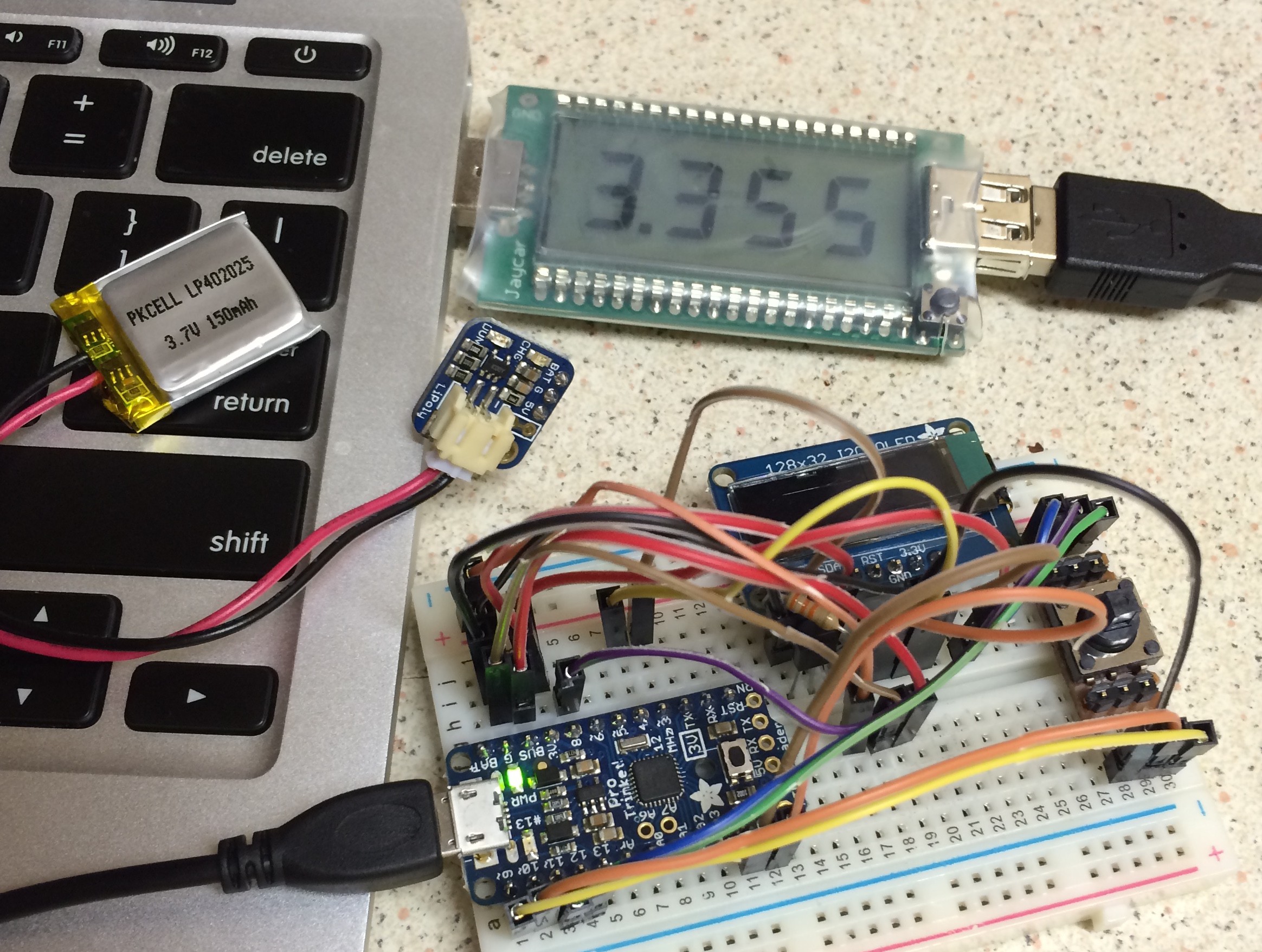
    I've hooked up one of the Trinket Pro LiPo backpacks - certainly a nice easy way to deal with powering it all off a battery. I also have a 150mAh and a 110mAh battery - both small and would work I think. I'm not sure which I'll go with as yet, but it will probably come down to shape more than capacity.

    Secondly, I spent some time sorting out the "sleep" mode on the Trinket. Without this the idea of a device you carry everywhere with you is pretty much doomed. Looks like the Trinket consumes around 20mA when powered up. The display adds a bit of course. At that rate of consumption, the small batteries I have would last all of 6 hours or so.

    The vast majority the time, the Insulin Minder won't actually be doing anything. It only needs to wake up periodically to record the temperature, and also when the user wants to use it (i.e. they move the navigation stick). By using the watchdog timer and the pin-change interrupt, the Trinket can use the POWER DOWN sleep mode which should be the lowest power consumption rate possible.

    A naked ATMega chip would consume only a few uA - an improvement of several orders of magnitude. The trinket however is consuming 3.3mA (measured using my handy-dandy USB power monitor). Thats still far too much. I THINK much of this is due to the power LED. Unfortunately the only way around this I know of is to actually remove the LED.

    Still, the main loop is now entering the lowest power state, and waking every 8 seconds or when I move the navigation stick. The rest of the code is almost just window dressing (well, remaining challenges will be drawing pretty text and measuring the battery voltage).

    Finally, I have set up a GitHub repository for the code and uploaded what I've done so far.


View all 12 project logs

Enjoy this project?

Share

Discussions

Jan wrote 02/27/2017 at 20:54 point

These are the projects which matter! Nice unit you built there. I'd love to see the mk2 soon. Btw: the li-po pack from adafruit you use has a built in protection against over-charging and deep-discharging :)

I don't know how precise your mill is, but 3 boards of that size are like 5$ incl. shipping @oshpark. Worth a try.

  Are you sure? yes | no

davedarko wrote 03/22/2015 at 18:39 point

You should make a photo of your working and enclosed prototype as your project profile picture - the current one looks like a mock up of stacked boards. Your video presentation was great!

  Are you sure? yes | no

Linus Dillon wrote 03/23/2015 at 02:50 point

Good point. Fixed now. Cheers.

  Are you sure? yes | no

DC3 wrote 02/02/2015 at 22:03 point

I hate to sound like I am trying to kill a great project (I am type 1 as well), but you can use temperature limit stickers to accomplish the same feature.

  Are you sure? yes | no

PointyOintment wrote 02/03/2015 at 23:45 point

Yes, feature. Not features. Can stickers do all of the things listed at the top of the Details section?

  Are you sure? yes | no

Linus Dillon wrote 02/05/2015 at 04:18 point

Had a quick google for these and came up empty. Any links I can check? I imagine they need to be replaced once they record an out of bound temperature.

  Are you sure? yes | no

Linus Dillon wrote 01/08/2015 at 08:24 point

Cool. Think I've won a t-shirt. :)

  Are you sure? yes | no

Mike Szczys wrote 01/05/2015 at 21:19 point

Wow, I hope you see this one all the way through to daily use. Great concept and you have a firm start on gathering all the features into a simple piece of hardware. Nice work!

  Are you sure? yes | no

Viper-Gtr wrote 12/12/2014 at 13:00 point
hi, really great project!
I am also a type-1 diabetic and am always happy when a small helper, is invented around this sector.
But on the contrary to you, i wear for two years a insulin pump. So although I have to take care on the solar radiation on the tubing. So the minder would come well for that use too.
keep it up! ;-)

  Are you sure? yes | no

Adam Fabio wrote 12/08/2014 at 02:46 point
This is a great project Linus! Not only is helpful every day, it could save your life!

  Are you sure? yes | no

Linus Dillon wrote 12/08/2014 at 11:50 point
Not sure about saving a life, but certainly help prevent unpleasant blood sugar spikes. :)

  Are you sure? yes | no

Similar Projects

Does this project spark your interest?

Become a member to follow this project and never miss any updates