 Stefan Lochbrunner
First off... here, have a rough sketch of what the device looks like:
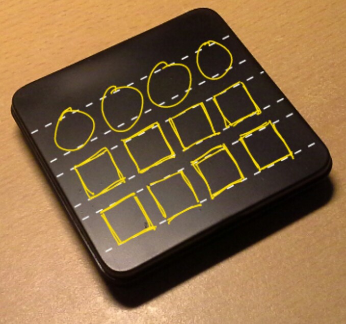
... as if I hadn't used it enough already ;)
TLDNR: SoB case templates on GitHub.
Seriously though, some thoughts on the case design:
As far as I can tell the most common ways to mount a rotary encoder are to solder it on top of the PCB (like all the modules found on eBay) or to directly mount it to the case.
When combining it with buttons though, the first option is problematic because the body of the encoder is higher that the buttons. This results in the buttons not protruding far enough through the acrylic (blue stripe, roughly 2.5mm thick) as illustrated in this image:
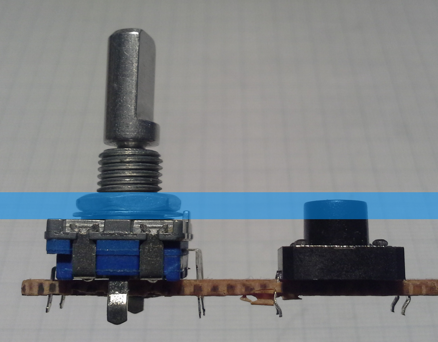
Of course this would have worked for the thinner tin case I used for the prototype but then the problem is that the threaded part of the shaft can't be shortened. This is also the case if the encoder is mounted to the case directly (the second possibility), as shown here:
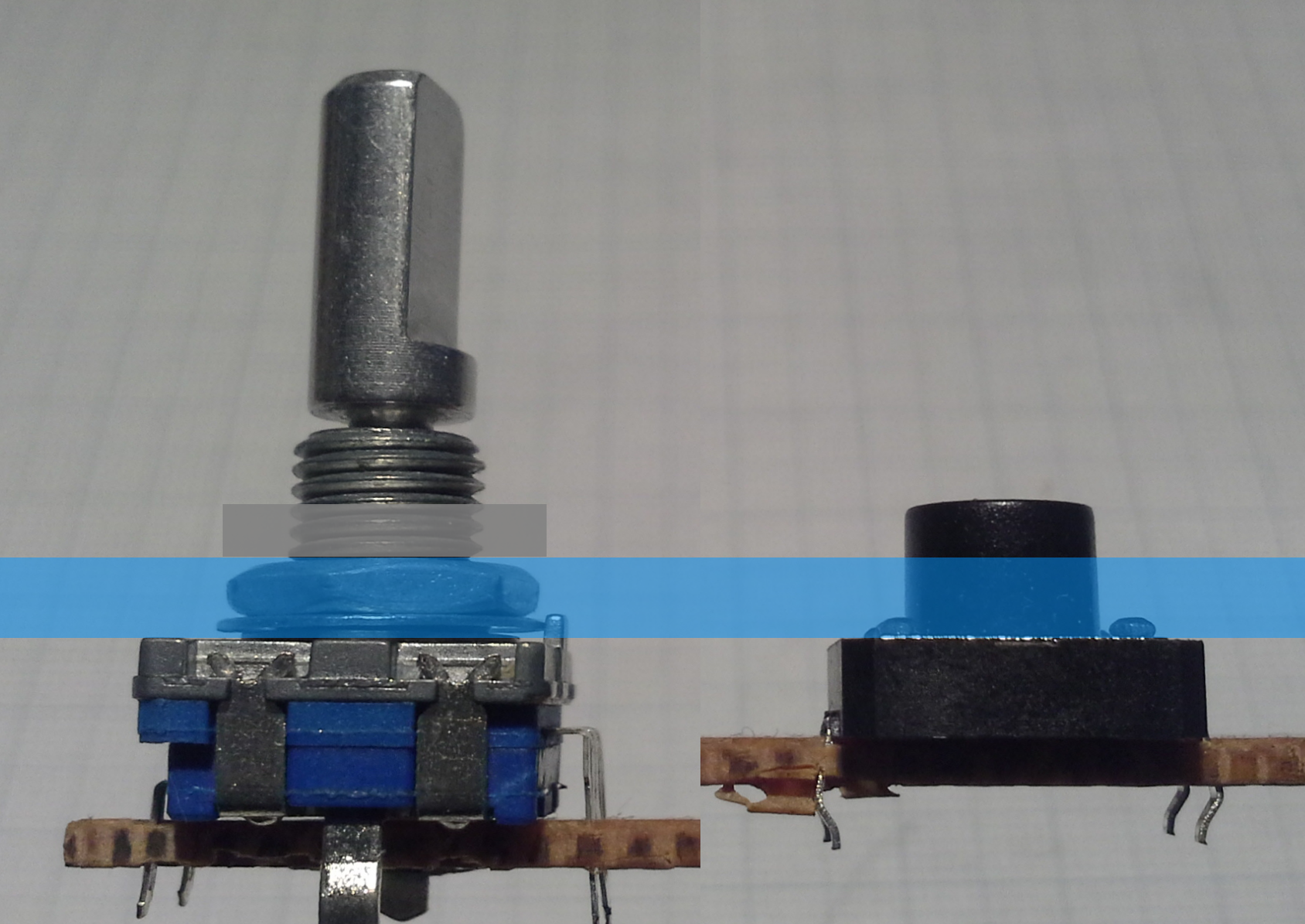
Another downside of this is that it requires two separate PCBs. Therefore I went with a third option that I haven't really seen anywhere else, which is to mount the encoder to the PCB. This leaves only the movable part of the shaft protruding through the acrylic:
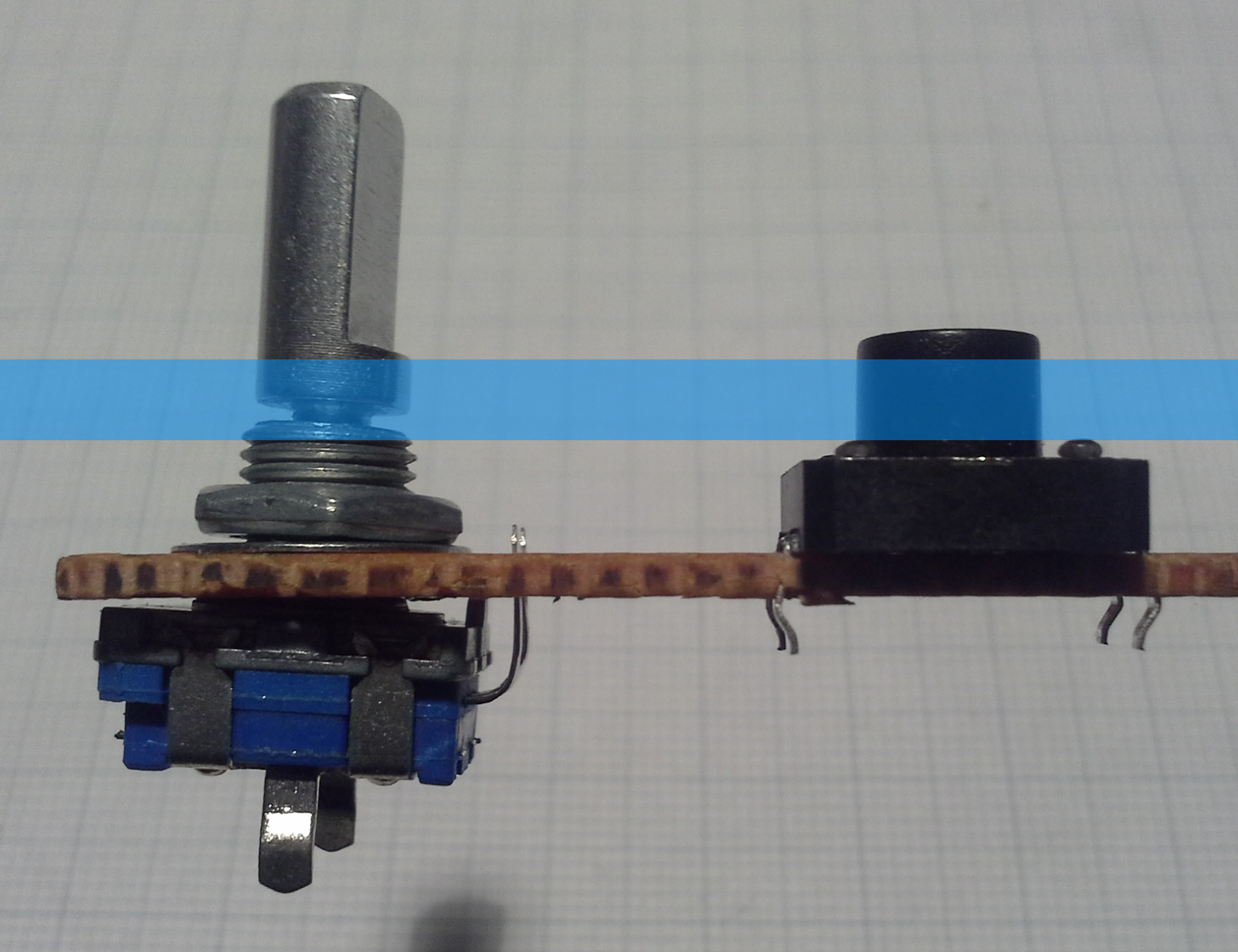
This is where the hole in the center of the rotary encoder footprint on the PCB, that I mentioned before, comes into play. The encoder can then be connected to the same footprint as if it was mounted on top. However, bending the pins upward can cause them to break off (as you can see on the left of the rotary encoder) but that's an easy fix. It's also important to make sure that the pins are not shorted to the body of the encoder. If the rotary encoder shaft is still too long in this configuration it can be easily shortened such that the knob sits just barely above the acrylic.
That was a lot of text and three quite similar pictures (...again, with the reuse of images...) for something that is quite obvious I guess...
Anyway, for the the actual acrylic case I ordered custom laser cut pieces from Seeeds Fusion service for the top half and the blank DP8080 case for the bottom. I didn't run the numbers but maybe ordering custom cut pieces for the bottom would be cheaper than the blank cases since it's a less complex job. However, with the blank case I also get the screws and the standoffs so I don't have to buy them separately.
To design the case I followed DPs guide with some exceptions:
- If you are like me, follow the link for the SVG plugin and look straight for the download, you might miss the fact that the plugin have moved to GitHub. There you'll find the .rbz file that plays nicely with the current version (15.2.685) of SketchUp.
- Exporting as .svg with a line width of 0 resulted in an empty file so I set it to 0.1mm.
- Contrary to the guide, it says on the Fusion laser cutting page that they only accept .eps, .cdr or .dxf files. Therefore I converted my .svg file to .dxf using Inkscape. I first tried .eps but even re-opening that file with Inkscape resulted in wrong dimensions. The .dxf version of the file didn't show that problem with Inkscape, however, Seeed seems to use CorelDRAW where it imported incorrectly.
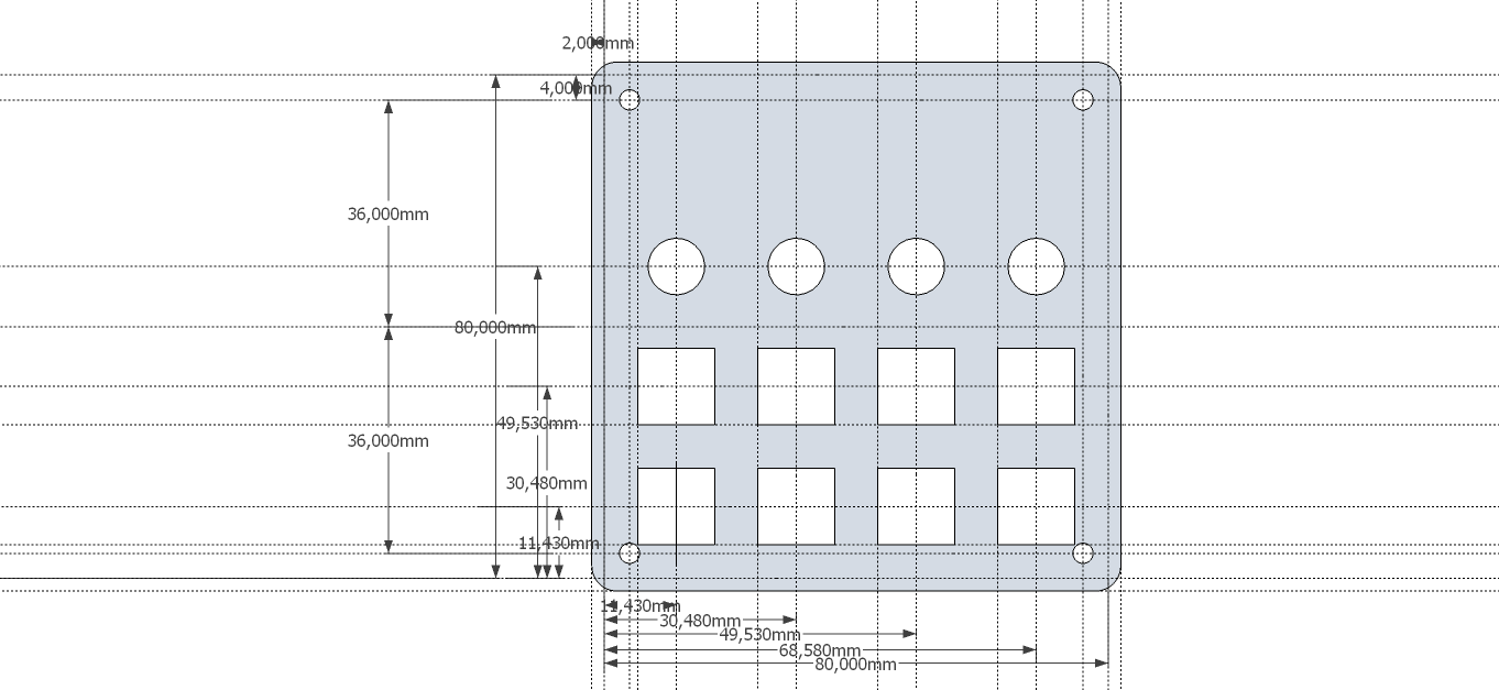
As you can see in the above image (and the files on GitHub), I made the openings for the buttons large enough to fit around the body of the button in case I want to use only 5mm high tact switches instead of the shown 8mm high ones.
Discussions
Become a Hackaday.io Member
Create an account to leave a comment. Already have an account? Log In.