Stefan Lochbrunner
-
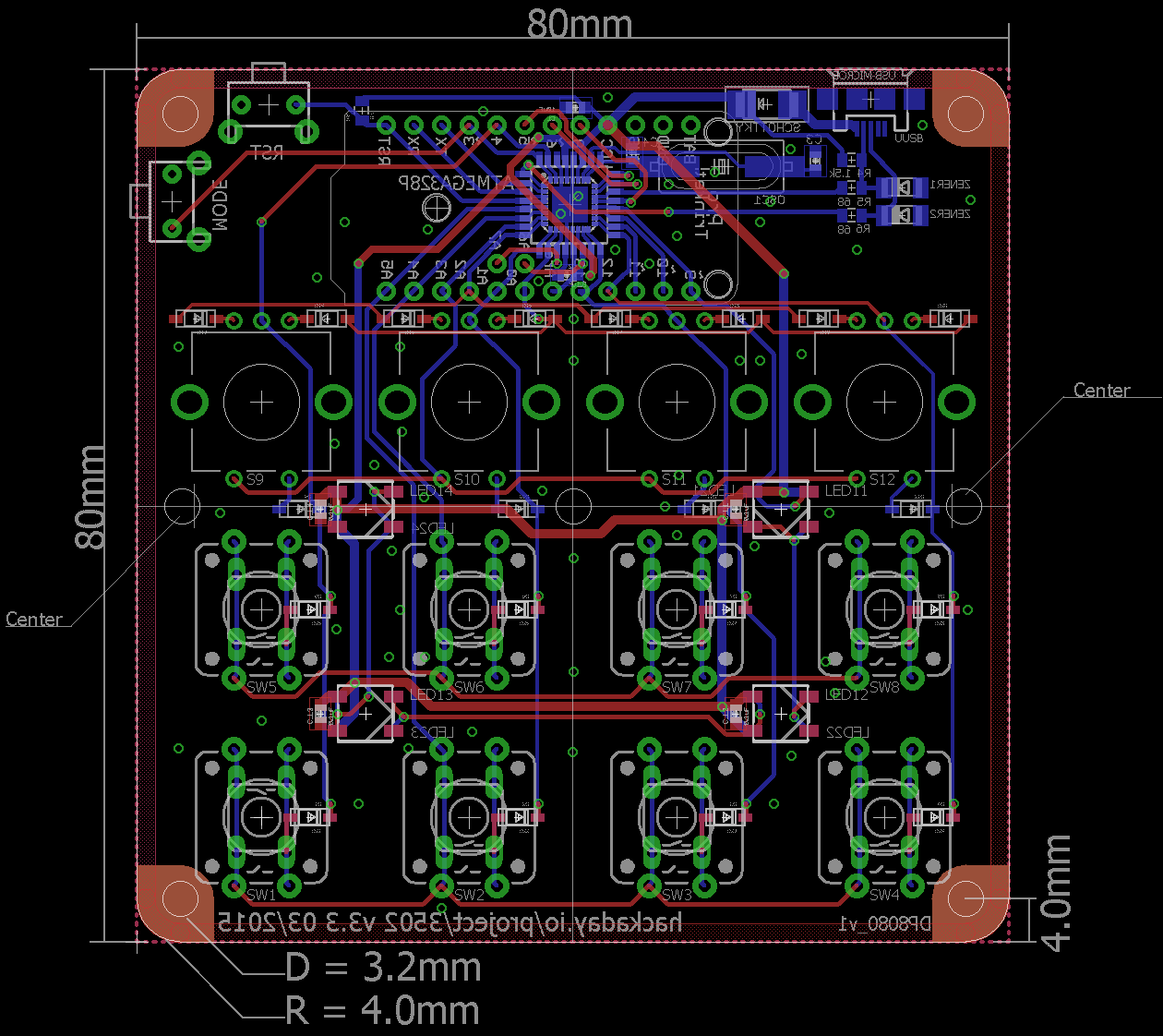
v4.2 hardware update
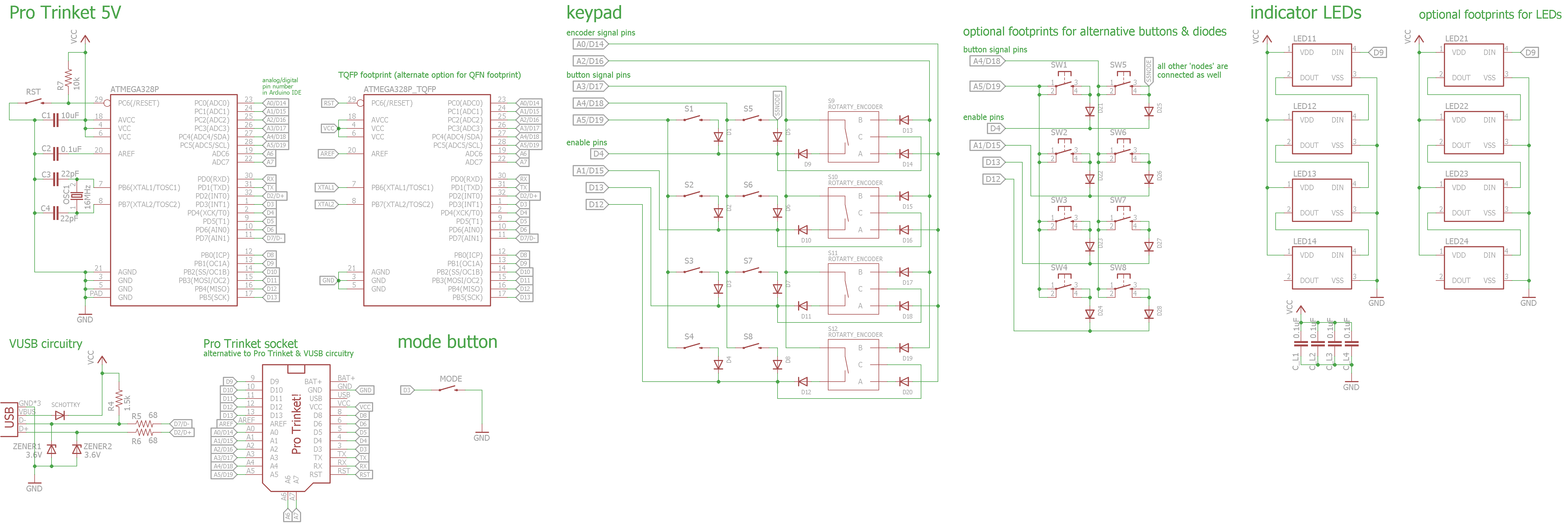
12/11/2015 at 00:21 • 9 commentsIt's v4 with I²C ports. Lots of I²C ports. GitHub.
![]() While the original premise of this project was that it could be easily redesigned to fit ones individual needs, @Craig Hissett convinced me to make it modular after all, just like its 'role model' Palette. Therefore, the I²C ports are for slave modules that can attach to this (master) module and extend it's functionality.
While the original premise of this project was that it could be easily redesigned to fit ones individual needs, @Craig Hissett convinced me to make it modular after all, just like its 'role model' Palette. Therefore, the I²C ports are for slave modules that can attach to this (master) module and extend it's functionality.![]() Like v4 it should work with the Pro Trinket as well as the Pro Micro. But since they have their I²C pins on different pins I added solder jumpers that can be set according to the mounted MCU board.
Like v4 it should work with the Pro Trinket as well as the Pro Micro. But since they have their I²C pins on different pins I added solder jumpers that can be set according to the mounted MCU board.
Since there are already buttons and rotary encoders the first idea for an accessory module was a sliding potentiometer, which is obviously heavily inspired by Palette again. However, I found it difficult to find commonly available sliding pots and not to mention Eagle footprints. So I had the idea to implement them as capacitive inputs as done by @CNLohr on his glass PCBs or similar to #Capacitive touch wheel by @bram. This also made me think if I should make a version with only capacitive inputs but I'm still not completely set on this. I'd appreciate some feedback on these last thoughts. -
Pro Trinket/Micro Keyboard Jr
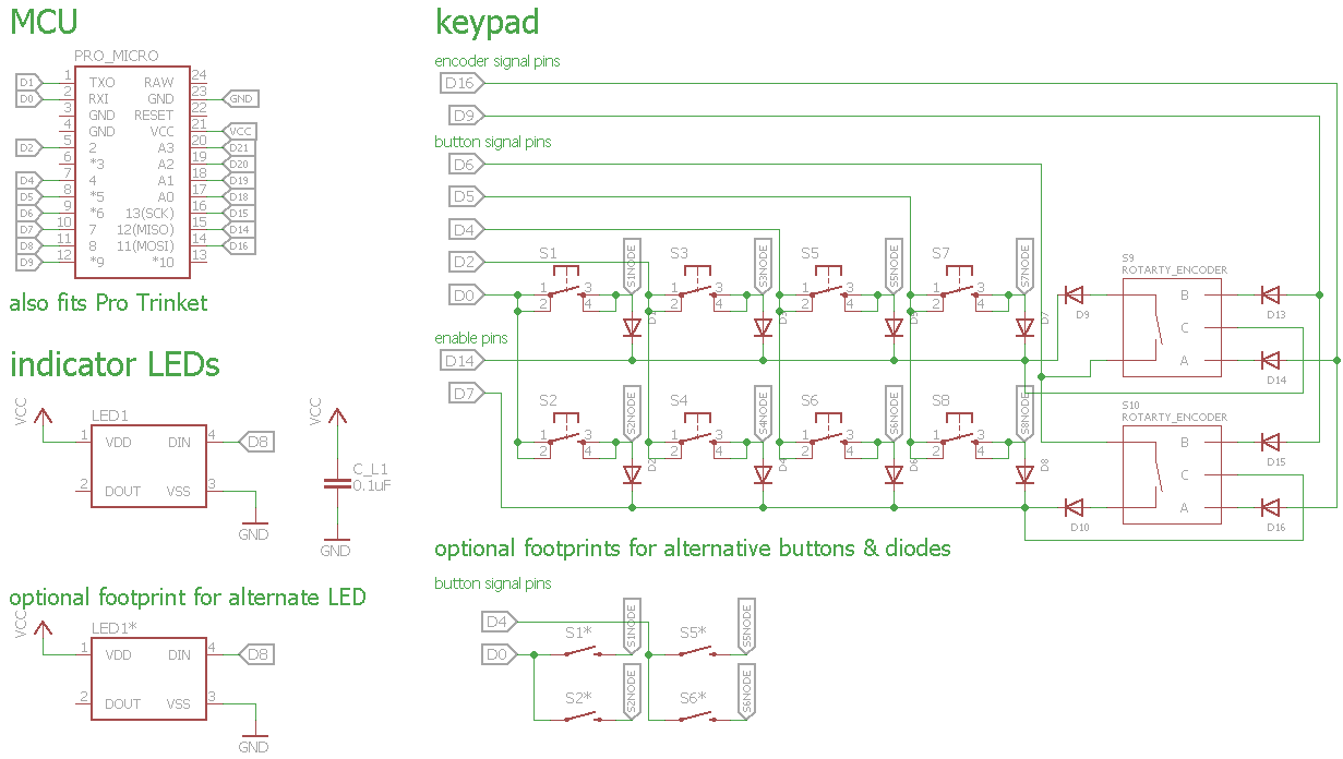
11/30/2015 at 23:09 • 5 commentsAs the name implies this is a device with almost the same functionality as the main Pro Trinket Keyboard but in a smaller formfactor. I have to give credit to @Craig Hissett for the inspiration for this device and since I could reuse a lot of the schematics it wasn't much work at all.
![]()
![]()
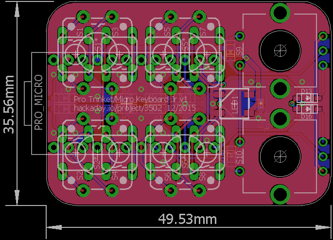
The hardware files are already on GitHub and the firmware will come once the hardware is available to develop and test on.As I said it hast almost the same functionality as the main device minus two encoders and their buttons and the mode button. The latter of which I may or may not have forgotten during the design but that should also be implementable within the keypad.
Edit 2016-05-08:
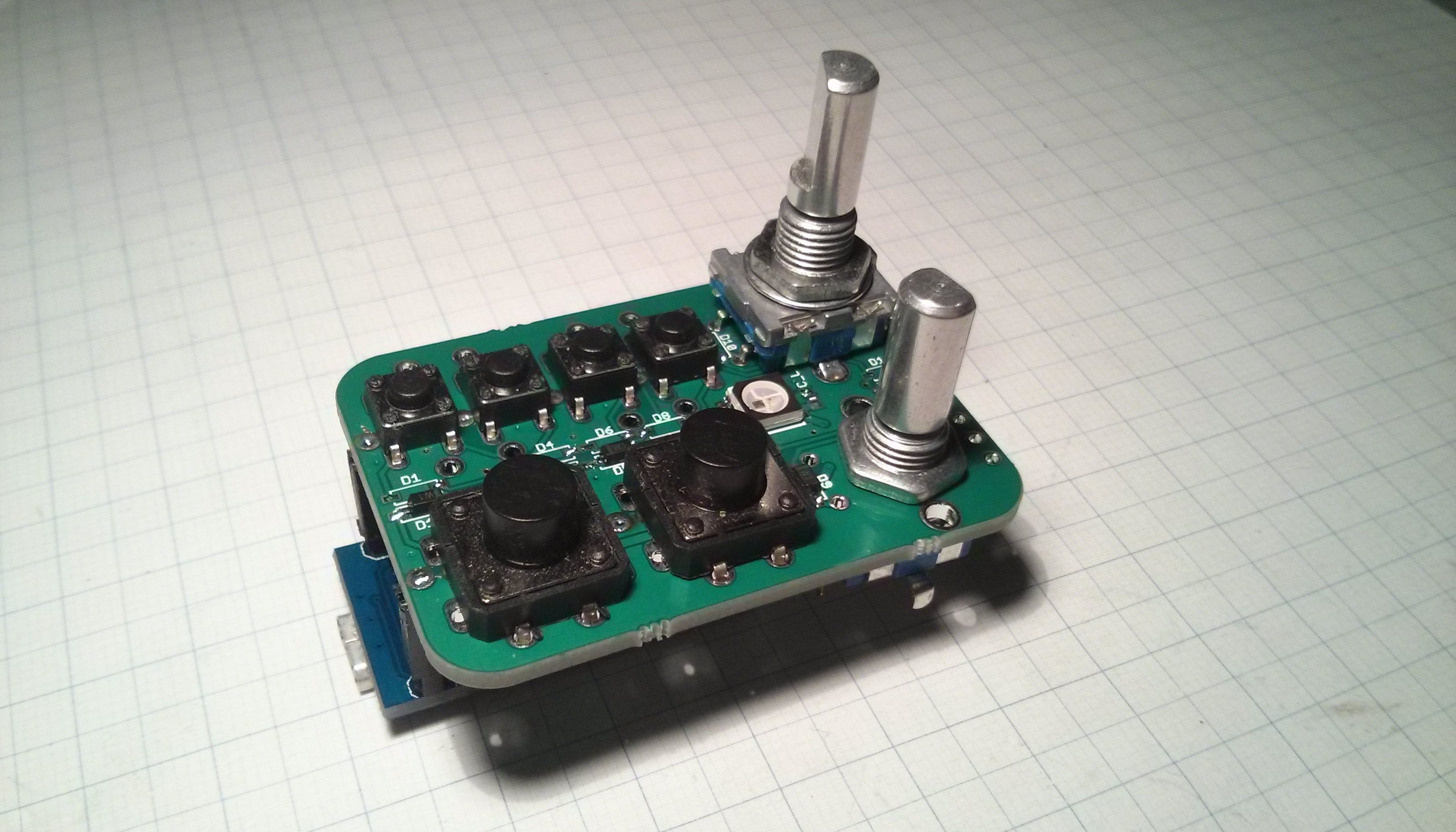
I finally got the PCBs and started assembly:
![]()
This is just to show off some different ways of how the board can be assembled. I used female headers to attach the Pro Micro because I only have the one and want to use it on the other board as well but usually you'd want the two boards connected together as thin as possible (eg. use just male headers with the spacer and trim off the excess length of the pins). I'm still missing some diodes but they are already on order so until I can finish assembly I can at least implement pin mapping in the software.
-
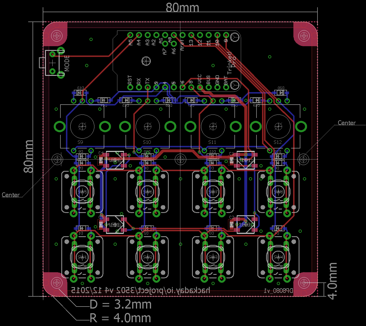
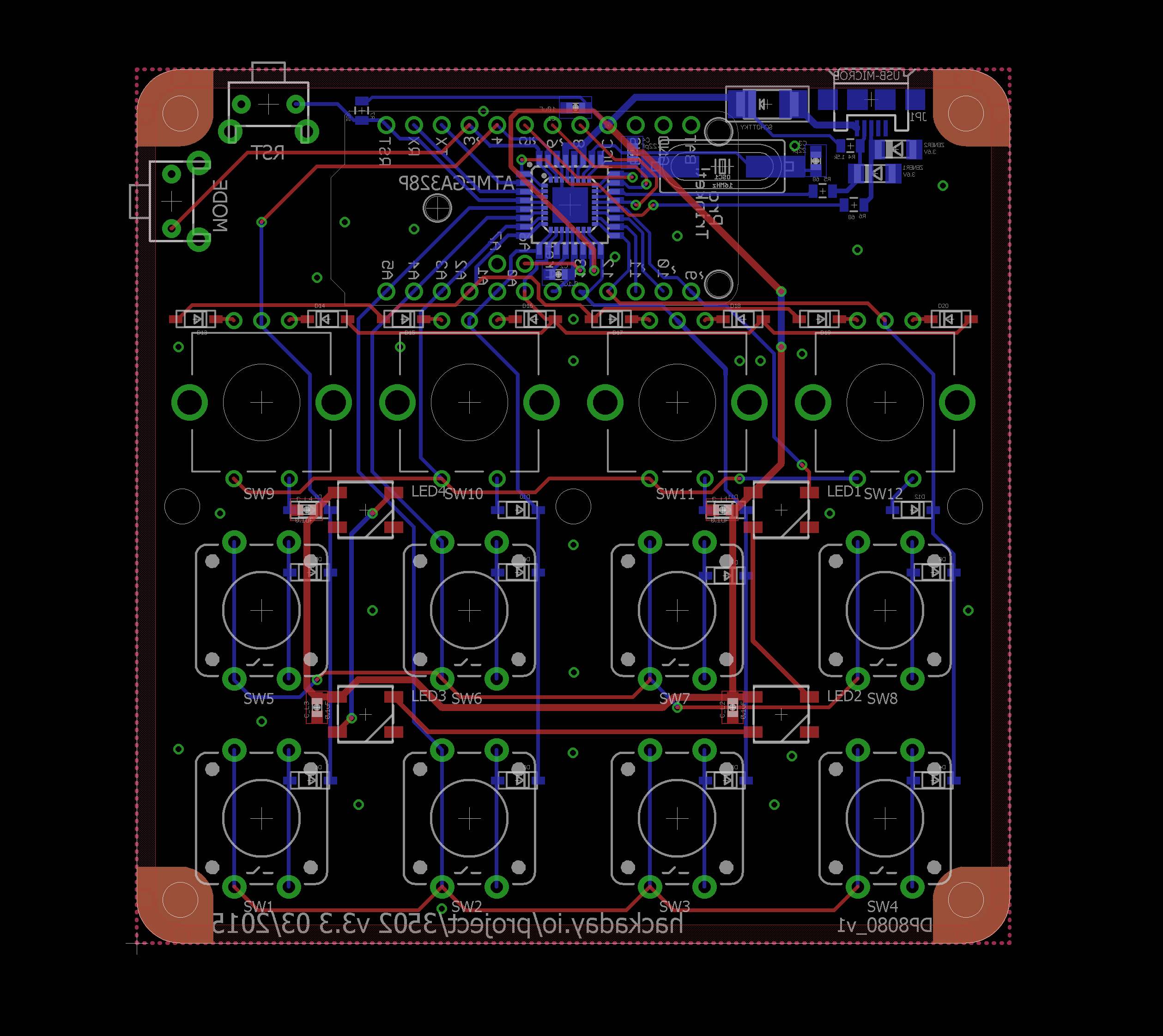
v4 hardware update
11/30/2015 at 21:20 • 8 comments![]()
Due to a critical mistake in v3.4a [that @Craig Hissett had to find out about the hard way ;) ] I, of course, deemed it necessary to do a correction but it was also kind of clear that a redesign might be in order. Here are some changes:
- Since everybody who built this keyboard wanted to use an external MCU (be it a Pro Trinket or Pro Micro) I decided to drop the footprints for the components that would otherwise make up the Pro Trinket circuit.
- Dropped optional diode footprints (introduced in v3.4a) to make assembly less confusing
- Rerouted whole board with Pro Trinket and Pro Micro compatible socket. More on this in the previous log. This way the USB ports of both boards also face away from the mode button.
![]()
-
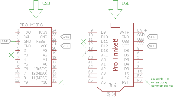
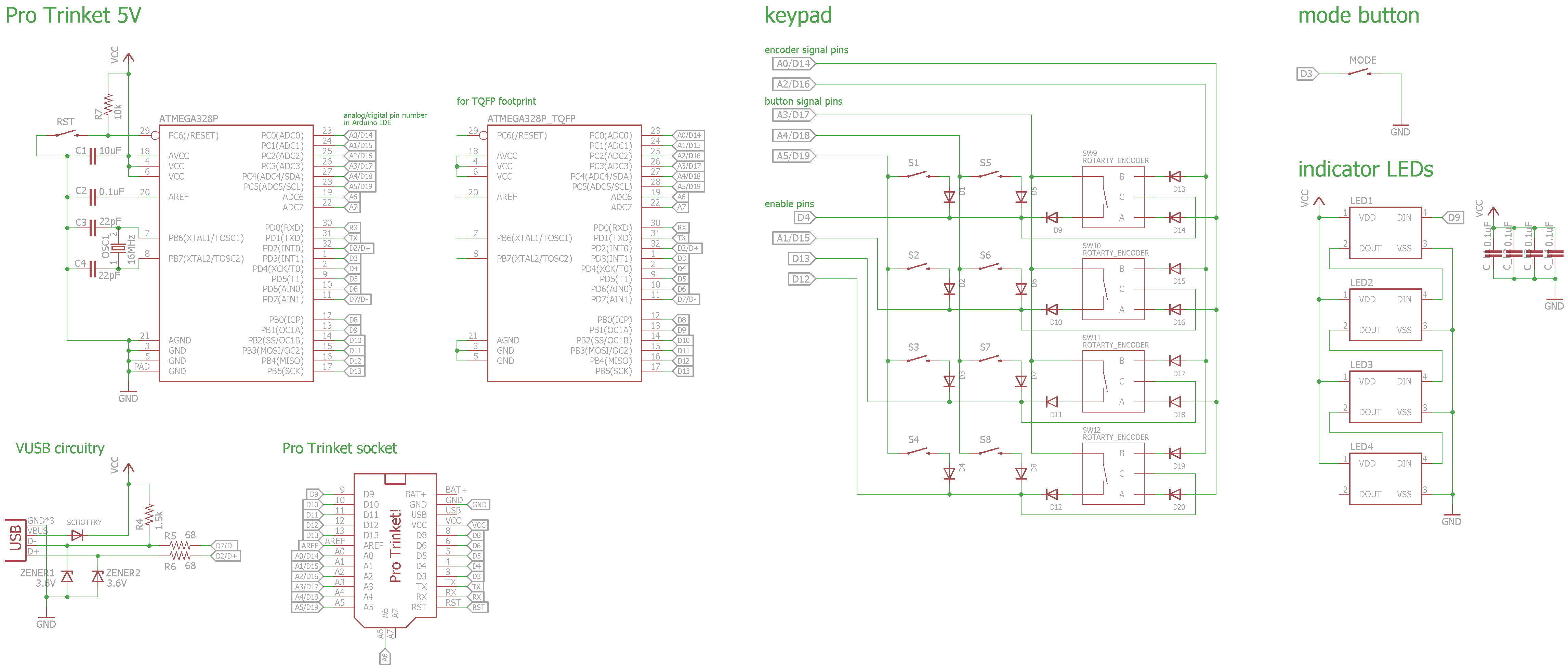
Pro Trinket and Pro Micro Compatibility
11/30/2015 at 20:14 • 1 commentIn preparation for the next logs I wanted to talk a bit about the pin compatibility between the Pro Trinket and the Pro Micro. The reason why I also want to integrate the Pro Micro is that it's more commonly available and cheaper.
![]()
The Eagle parts shown above for both boards pretty much correspond exactly to the actual pinout (besides A6 & A7 on the Trinket and pins 11-13 on the Micro). From these parts we can see that Vcc and one Gnd connection line up such that it would be possible to have a socket fit both boards. Of course, some other pins (e.g. Aref, RST) don't line up which means those pins and the corresponding pins on the other module can't be used and will not be connected on the socket. But there are still enough IO pins that line up with IO pins on the other module for all the in- and outputs of this project.
Using a common socket for both boards means that the software won't work without modification but since they use different implementations of their USB functionality more modifications are required anyway.
For future reference, here's a list of pin correspondencies between the two boards:
Pro Trinket Pro Micro 0 16 1 14 3 15 4 18/A0 5 19/A1 6 20/A2 8 21/A3 9 1 10 0 13 2 14/A0 4/A6 15/A1 5 16/A2 6/A7 17/A3 7 18/A4 8/A8 19/A5 9/A9 -
v3.4 hardware update
10/20/2015 at 19:44 • 17 comments![]()
A minor update, implementing some more of @davedarko's suggestions.
Changes:
- Added footprints for smaller (6x6mm) tact switches
- Added footprints for WS2812B's and diodes to the bottom layer and top layer, respectively. This allows the the board to be used with either side up.
- Some rerouting, especially the of WS2812B supply traces
![]() ---------- more ----------
---------- more ----------Update 2015-10-29:
I couldn't help it... and made a version for the Pro Micro, v3.4 a.
![]()
I just swapped the Pro Trinket footprint for the Pro Micro one and did some rerouting.
![]()
Unfortunately I had to rotate and mirror the footprint such that the uUSB connector points towards the mode and reset buttons which might be problematic but it's nothing a good hacker couldn't fix ;)
Update 2015-12-11:
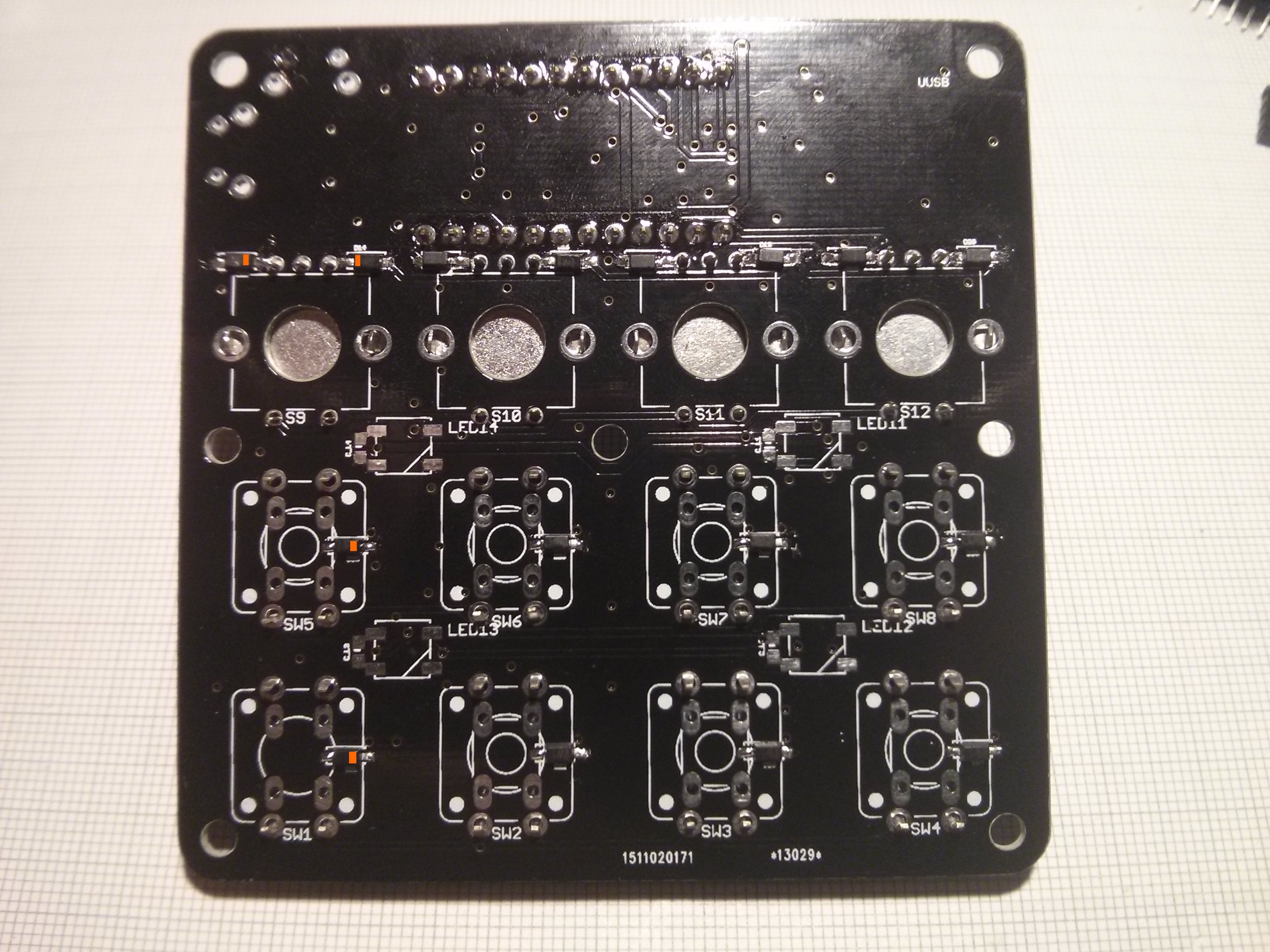
There are a few problems/errors with v3.4a so I'd recommend not to make/order this board anymore and instead use v4 or higher [... so you can test it and tell me about the errors ;)]. However, since there are a few boards of this version out there, here are some notes:
Despite the orientation markings being in the design (as seen above) they apparently didn't make it onto the board... hopefully the orange markings in these images clarify that:
![]()
![]()
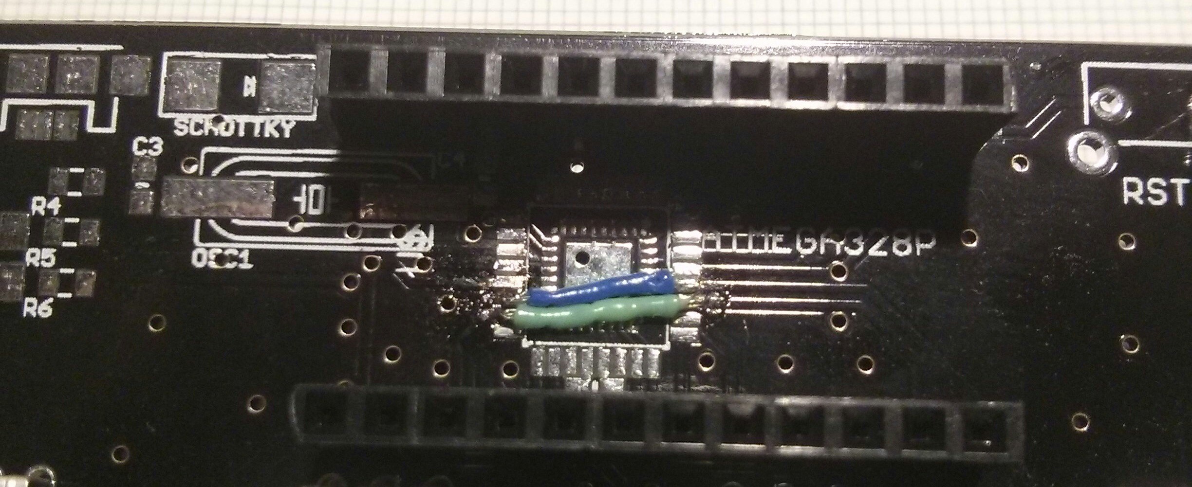
One of the errors on this board was that the bottom two rows of buttons were not connected to the Pro Micro footprint. This can be fixed by bridging the signals across the ATmega328 footprint(s) like this:
![]()
Since this is just a test bed for me I didn't solder all the LEDs (or buttons and encoders; they should make good enough contact as is) and initially I soldered it in the wrong spot... it's clearly an advantage if one can read the silkscreen...
-
v4 sketch makes use of multimedia keys
09/26/2015 at 17:35 • 1 commentThis has been long overdue... I finally updated the sketch to make use of the multimedia keys. Implementing this was a little annoying because the the multimedia keys (and mouse movement, which is not yet implemented) require a different function to be called than 'normal' keys and the keycodes that can be used for those functions overlap. For now the colliding 'normal' keycodes (ctrl, shift, alt & gui) are ignored in favor of the mmkeys. This goes only for the bare keys, they still work as modifiers. It's not ideal but at least volume control finally works. I thought about using another variable to distinguish between normal, mmkeys and mouse movement but that array is already way too confusing as it is.
edit 2015-09-27:
Initially I added some exceptions for ctrl, shift, alt & gui to be usable with the pressKey functions instead of invoking pressMultimediaKey. However, that didn't seem to work and while playing around with it I discovered (while writing the 1st version of this update ;) ) that you can also use the corresponding modifier without a keycode (well, more specifically kyecode 0). So it seems ignoring those codes will work without limiting functionality but now the problem is that my code doesn't allow for keys to be held down. One solution to this would be to make another exception for keycode 0 to toggle the modifier(s) on press and release. I'll look into this...
-
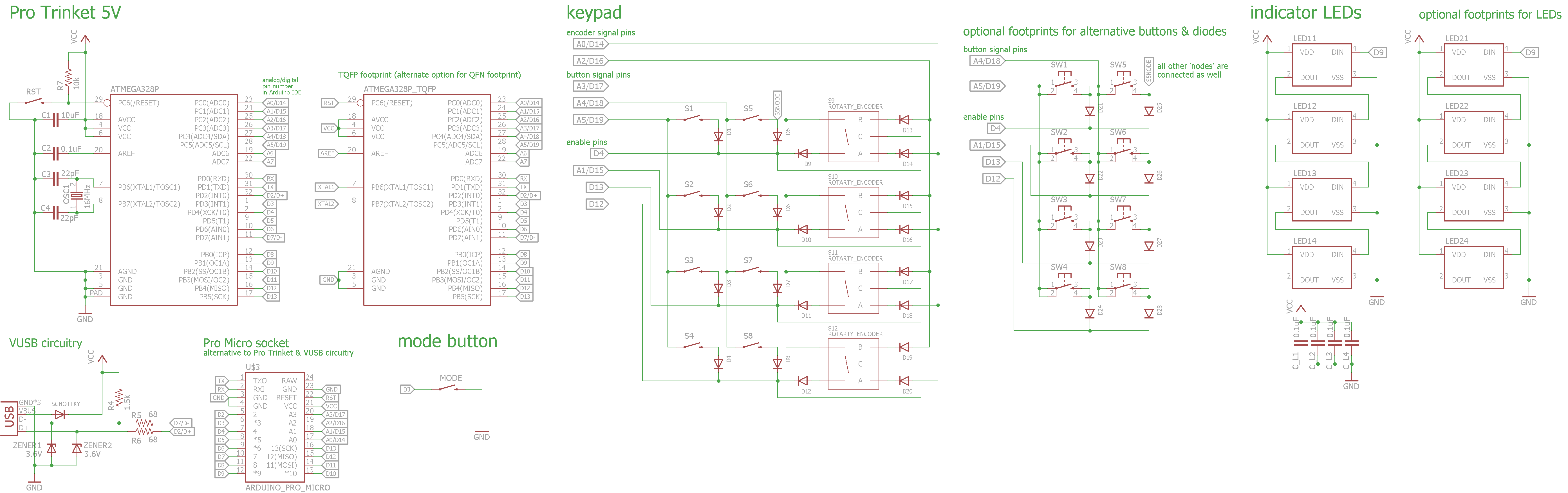
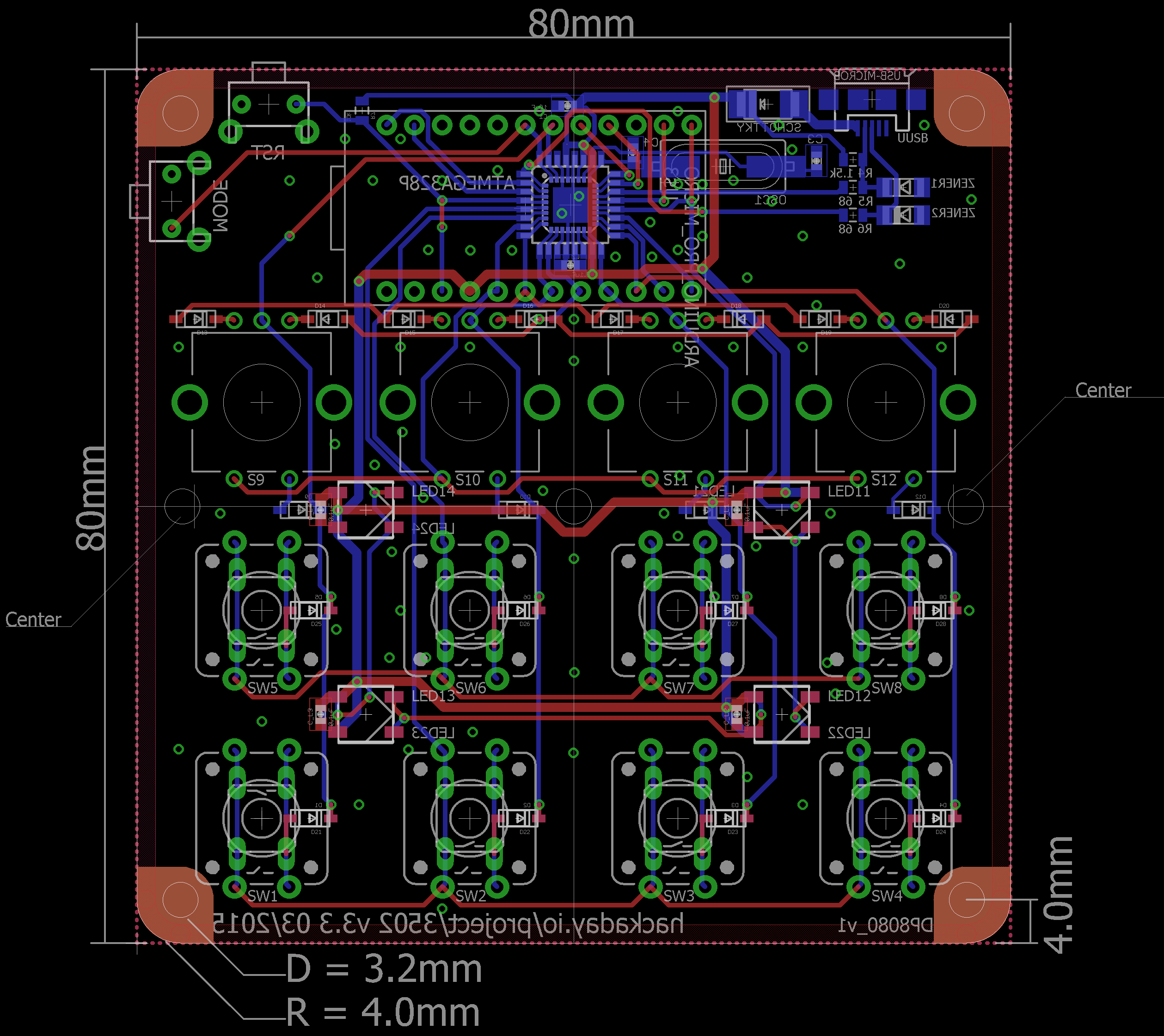
v3.3 schematics & PCB update
09/26/2015 at 13:32 • 4 comments![]()
As per @davedarko's suggestion I added diodes to the keypad and encoders to prevent ghosting. While I was at it I also switched the LEDs to WS2812B's to allow better color mixing and 'doubled' the amount of LEDs to better illuminate to top piece of acrylic. Files on Github.
![]()
I'm not sure if the USB and WS2812B will work right out of the box or if disabling the timer will be a problem. If it is a problem, I also uploaded a v3.2 schematic and board that have the diodes but not the WS2812Bs.
Since I still have a lot of the old boards I won't be ordering these but hopefully the schematics will be useful to someone.
Update 2015-10-03: A quick test showed that the WS2812B's work fine with this library.
-
Move to Adafruits ProTrinketHidCombo lib
06/02/2015 at 22:47 • 0 commentsTLDNR: what it says in the caption, v3 sketch on GitHub.
A few days ago I started moving the sketch to the (relatively) new ProTrinketHidCombo library directly from Adafruit thinking it would be an easy task...
Besides the VUSB for Arduino linrary not compiling in the 1.6.4 IDE the ProTrinketHidCombo lib has the advantage (as the name implies) of 'complete'(?) HID functionality meaning not only keyboard but also mouse and multimedia key functionality.
I ran into similar problems as before with the device not properly re-enumerating and the like. Going back and forth between this one and the working VUSB for Arduino library I found out that the thing that was missing to make it work was to disable the timer 0 overflow interrupt in the beginning of the usbBegin() function in ProTrinketHidComboC.c (starting in line 32). The changed function now looks like this:
void usbBegin()
{
  // disable timer 0 overflow interrupt (used for millis)
  TIMSK0&=!(1<<TOIE0);

  // Clear interrupts while performing time-critical operations
  cli();

  // run at full speed, because Trinket defaults to 8MHz for low voltage compatibility reasons
  clock_prescale_set(clock_div_1);

  // fake a disconnect to force the computer to re-enumerate
  //PORTD &= ~(_BV(USB_CFG_DMINUS_BIT) | _BV(USB_CFG_DPLUS_BIT));
  usbDeviceDisconnect();
  _delay_ms(250);
  usbDeviceConnect();

  // start the USB driver
  usbInit();
  sei();
}
Another minor thing with this function is that the write to PORTD (or PORTB as it says on their GitHub) is redundant. As the comment states this is intended to force re-enumeration which can be done by forcing D- (and D+) low. D- and D+ are on port D not B, pins 7 and 2 respectively. With the 'Optional Hardware Config' section in usbconfig.h commented out, D- is already being forced low by usbDeviceDisconnect() found in usbdrv.h (starting in line 298).
As you might know I'm not using a genuine Pro Trinket but I don't think that should make much of a difference. I'd be interested if the library and the included example work without modification on a proper Pro Trinket.
edit:
Obviously if you disable the timer overflow interrupt right before initializing the library, there is no need to modify the library.
TIMSK0&=!(1<<TOIE0);
TrinketHidCombo.begin();
edit 2015-09-26:
added link to the post about the library above
-
Re: switch bouncing
05/20/2015 at 23:35 • 9 commentsI played around with some capacitor values to get rid of the bouncing of the tact switches. I tried some caps in the pF an nF range but they either had no noticeable effect or lead to the neighboring button in the next column being read as pressed as well. Implementing a proper RC filter (with no footprints for the resistors) didn't improve it much either. However, adding some software debouncing in the form of 250us delay after a column is polled pretty much got rid of the bouncing, I haven't been able to replicate the issue since. This goes for for all of the above mentioned configurations (including no caps) so I'm glad I won't have to change the PCB... at least until a major redesign.
-
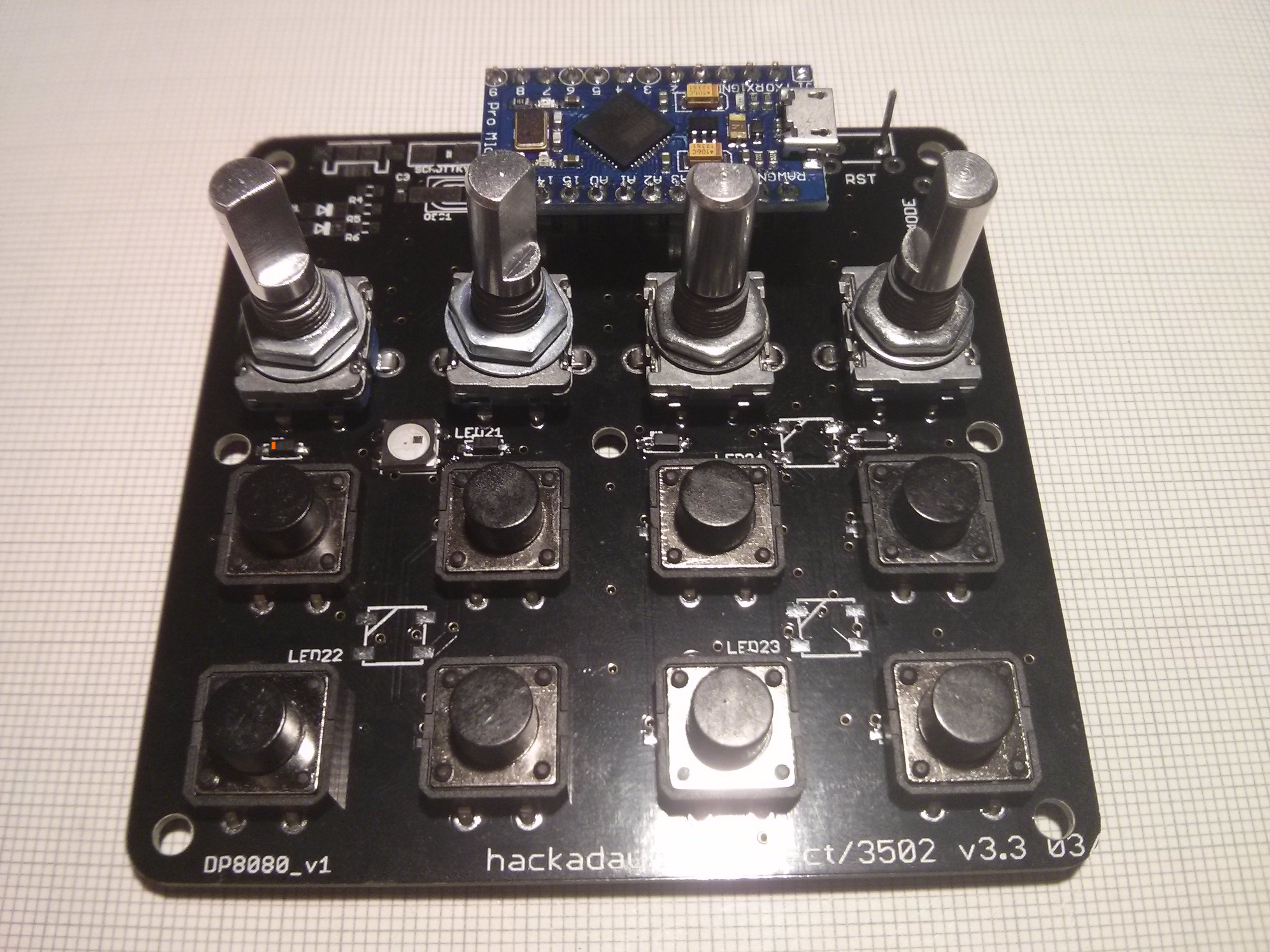
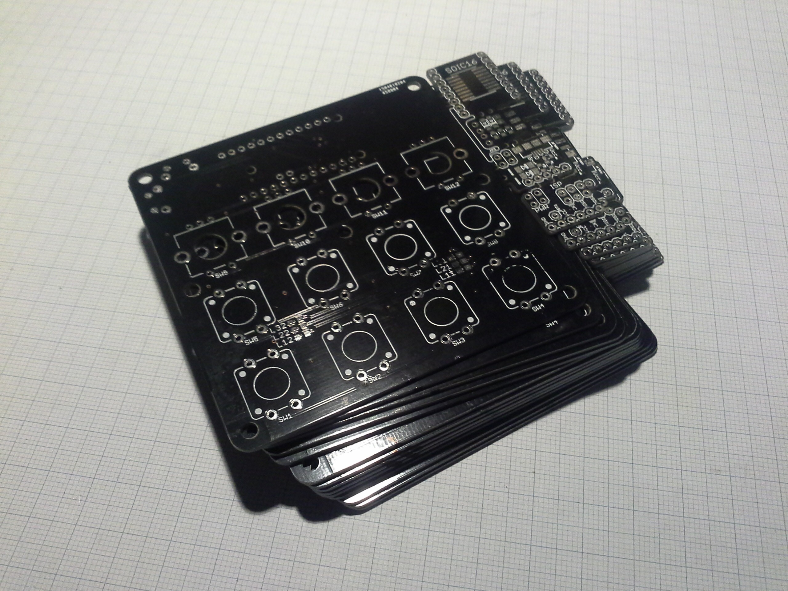
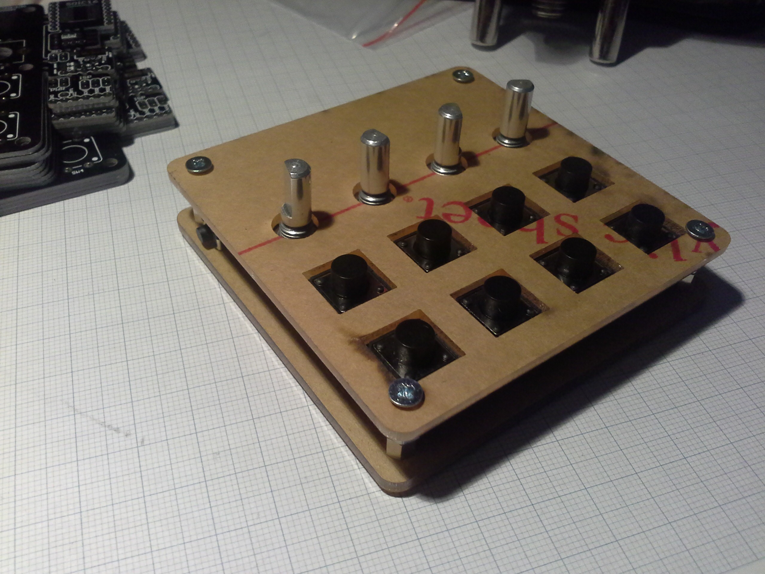
Final (?) assembly
05/09/2015 at 16:42 • 1 commentThis week I finally received my order from DirtyPCBs (after anxiously waiting for about a month):
![]()
To make better use of the area I added some breakout boards and some other things I wanted to try out. Besides some silkscreen issues on a few boards they turned out great and for that price I can't complain.
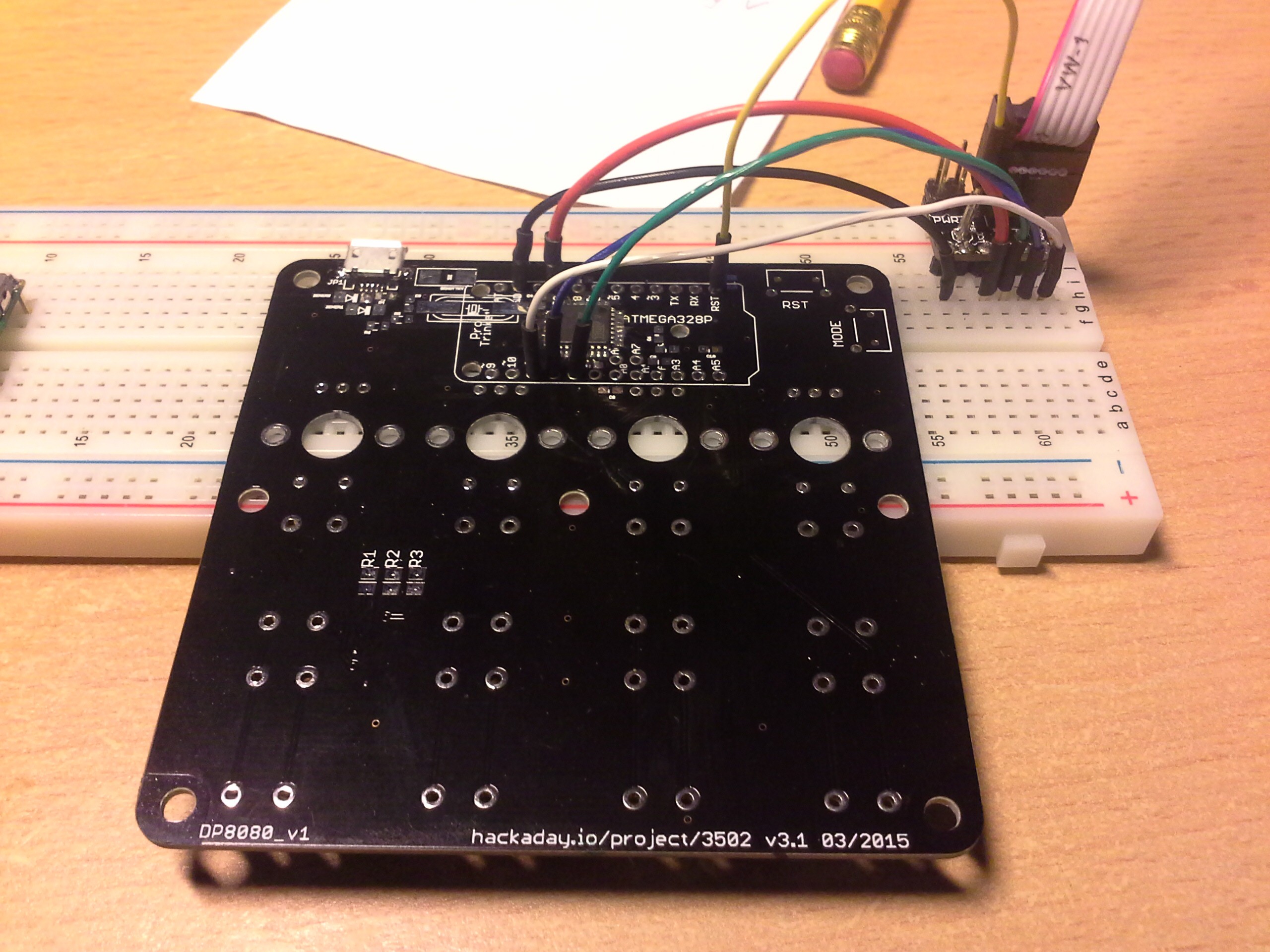
If you looked at the schematics and board layout you might have noticed that I left out an ISP header. Routing the reset signal to the other side of the chip where the MOSI, MISO and SCK pins are just seemed like too much work if I could access these signals via the Pro Trinket footprint. Therefore, to program it I put it on a breadboard and made the connections with jumper wires:
Pressing the wires against the board or vice versa worked good enough for the few boards I'll assemble.![]()
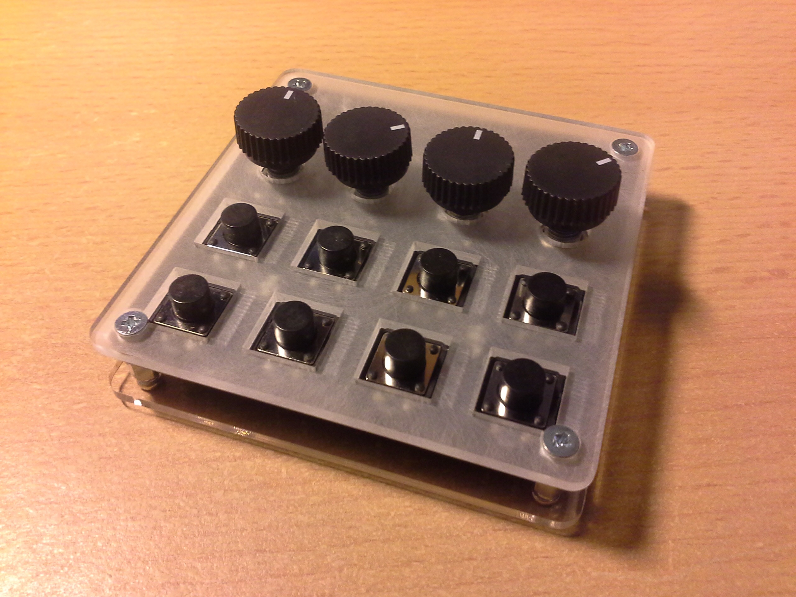
While I was waiting for the PCBs I also received the custom acrylic pieces for the top of the case...
... and after counter sinking the screw hole and some sanding I got a case that looks quite nice:![]()
The purpose of sanding the bottom side of the acrylic was to diffuse the light of the LEDs so they would illuminate more of the case instead of only showing up as little spots.![]()
All in all I'm really happy how everything turned out:
![]()
As mentioned in another log, I had to change some pin assignments due to some differences in the pinouts between the DIP and the TQFP. The updated sketch is on GitHub as V2.
Another thing I mentioned was the occasional bouncing in the prototype. Unfortunately this problem still persists (mostly when quickly tapping a button quickly) but that's what I added the capacitor footprints for. However, even without the capacitors the keyboard is quite usable since using a shortcut doesn't require fast typing... and I'm surely not going to write a project log with it.
Adding the capacitors brings up another issue, which is that a charged capacitor will cause the neighboring button in the next column to be read as pressed as well. The solution to this is to add enough delay between activating the columns to allow the capacitor to discharge below a certain threshold. I'll look into this some other time but for now I consider this project done.
Update 2015-10-20:
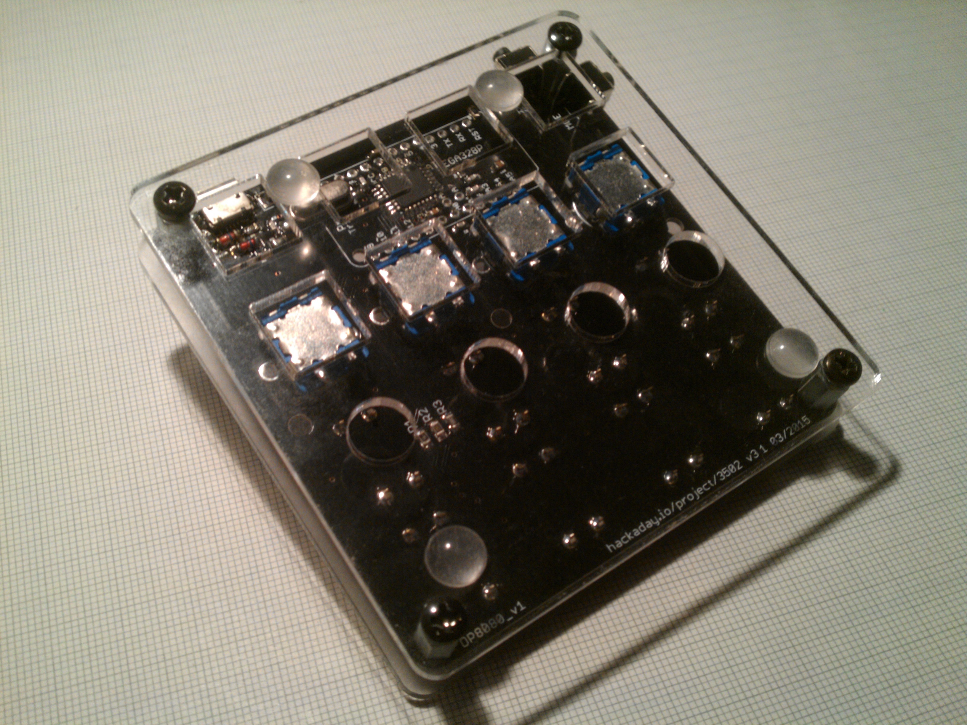
Some more pictures to clarify assembly:
Bottom side:
![]()
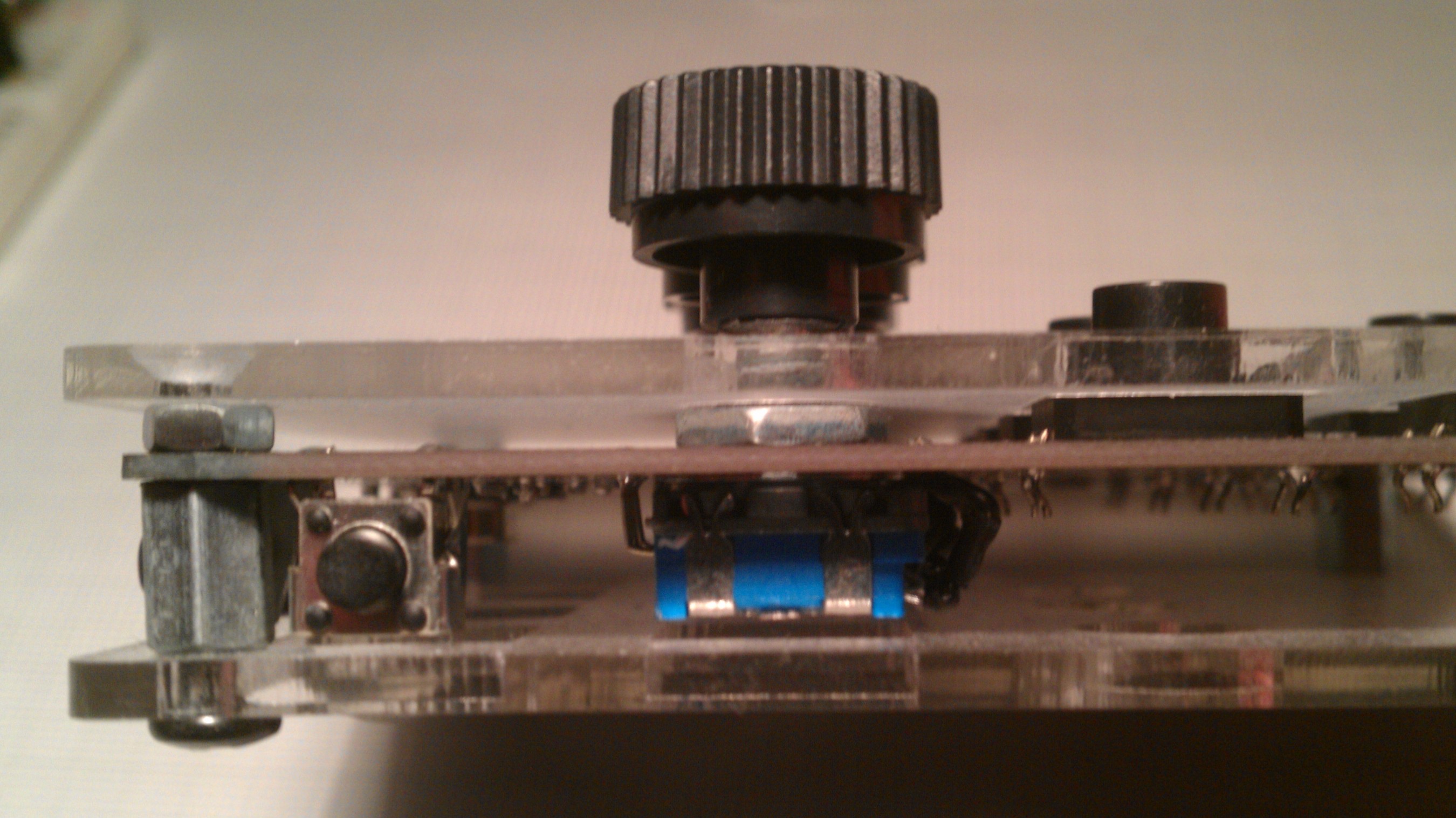
Mode button on left side:
![]()
Pro Trinket USB Keyboard
A USB keyboard for custom shortcuts based on the Pro Trinket and Pro Micro
 While the original premise of this project was that it could be easily redesigned to fit ones individual needs,
  Like v4 it should work with the Pro Trinket as well as the Pro Micro. But since they have their I²C pins on different pins I added solder jumpers that can be set according to the mounted MCU board.