-
The joy of learning by doing
01/03/2015 at 17:24 • 0 commentsThe deadline of the contest is nearly here; it's time for me to post a final project log. During this month, I learned a lot and I had a lot of fun. But the main lesson I learned is : just do it.
I have spent a lot of time finding good reasons to not start an electronic project. This was a mistake. I have many things to learn, but now I'm convinced that the best way to learn something is by doing it.
I know that the Portable Trollmaster 3000 is mainly an 'embedded programming' project and not really an 'electronics' project. I have everything to learn in the field of analog electronics and RF. However, I think that the Arduino/Trinket pro is good entry point into this world. It was really fun to use and thus it is a real motivation to go further :-) -
The joy of portability
01/03/2015 at 16:50 • 0 commentsAt the moment, the Portable Trollmaster 3000 is not very ... portable. Time to change this !
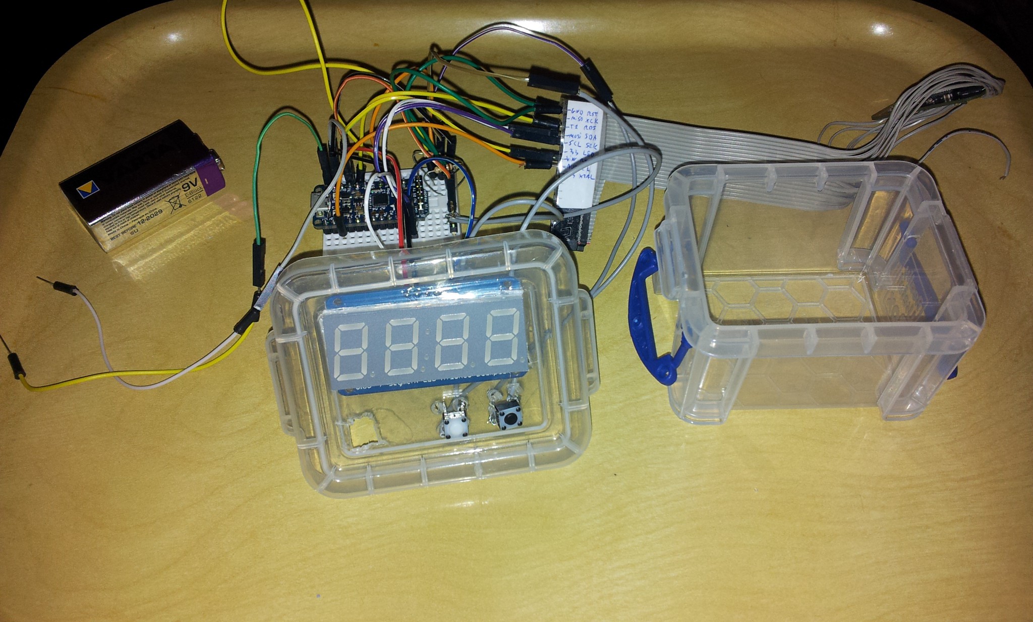
Thanks to the integrated voltage regulator on the Trinket Pro, it can easily be powered with anything up to 16V. A 9V lithium battery will do the trick. I found a nice litte enclosure. It's about 7 cm wide, 6 cm deep and 4.5 cm high. Ok, I admit it, it's a little bit larger than an Altoid enclosure ;-)
![]()
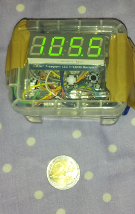
After rewiring everything on a smaller breadboard and cutting the lid of the enclosure, here is the final product :
![]()
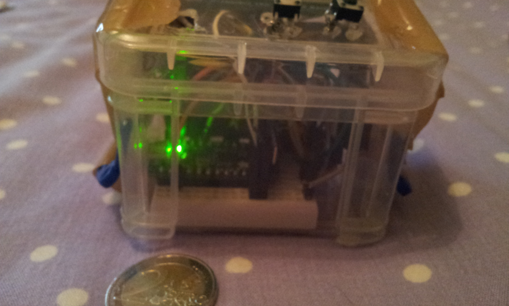
Since I had no banana for scale near me, I used a 2 euros coin. I had to use some tape to fix everything in place. It's a little crowded in there ...
![]()
You can see it in action here :
As you can hear in the video, there is a lot of noise when I move the enclosure. I guess the audio carrying wire is too close from the voltage regulator or another noise source. I guess a major improvement would be to design a clean PCB for this project. I have never done this before and I'm a little afraid to work with chemical products.
-
The joy of seeing the Trollmaster in action
01/02/2015 at 10:57 • 0 commentsHere is a video of the Trollmaster in action. Don't forget to turn Youtube annotations on. Enjoy :-)
The seven-segments display shows the FM frequency. Two push-buttons allow to change the frequency up or down by steps of 0.5 Mhz.
The Trinket Pro runs the PCM library of 'low-high tech' and loops a sample of the Trololo song. It also drives the MMR-70 FM transmitter which generates a FM+RDS signal with a station name of "TROLL FM".
-
The joy of using an underdocumented module and using a plan B at the last minute
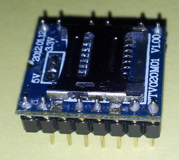
01/01/2015 at 22:04 • 2 commentsMeet the culprit, the WTV020M01 module :
(Yes, one pin broke during transport).![]()
This thing is a "MP3 audio player SD card module". That's for the title. Now a few teeny tiny details :
- By "MP3", it means that it supports 'next', 'prev', 'stop' and 'play' buttons like classic MP3 players, NOT that it is able to read MP3 files. Really. It does not support the mp3 format.
- By "SD card", it means that it only works with Sandisk Micro SD card of 1 or 2 GB. According to reviews on the Internet, you have to try dozens of cards to find a compatible one.
- By "audio player", it means that somebody on the Internet says he knows someone who got it to read a .wav file. But nobody can reproduce that. Instead, you have to use the obscure .ad4 file format
- The datasheet is written by a Markov chain. It looks like a datasheet, it has the structure of a datasheet, some words seems to make sense, but in the end, it is just pure randomness.
Caveat emptor : do not buy this thing ;-)
Ok, maybe it's just me. After all, it's my first real project. But after spending two days to get this thing working, I give up. It is supposed to work in a standalone fashion, it does not. It is supposed to work with a weird two wire interface, it does not. All I managed to get is some kind of static. At least this static lasts the duration of the sound supposedly played. I do not have the tools or the skills to debug what's going on so, time to move to plan B.
I'm now using the PCM library from "high-low tech". It allows me to load a small (~ 3 sec.) low quality sample in the Trinket Pro flash and play it through an output pin. I'm disappointed that I cannot play the whole Trololo song but the deadline is approaching and I still must deliver a minimum viable product.
I quickly hacked the PCM library to loop the sample instead of just playing it once. It's really easy : in the ISR after the call to stopPlayback(), just add a call to startPlayback(sounddata_data, sounddata_length); and the sample will loop forever !
I used Audacity to extract a sample and sox to convert it to 8 Khz :
sox in.wav -c 1 -r 8000 -u -1 out.wav
Then, I used the EncodeAudio tool to get the set of bytes to paste into the Arduino sketch and voilà !
The setback with the nonworking so-called MP3-SD module was annoying, especially with the deadline approaching. But in the end, the PCM library offers a quick work-around, even if it means only playing a part of the Trololo song.
-
The joy of RDS
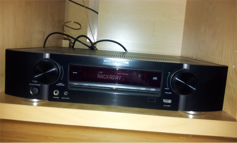
12/29/2014 at 21:52 • 3 commentsA picture is worth a thousand words. Admire the FM tuner of my AV receiver displaying the name of the famous HACKADAY FM Radio :D
![]()
Basically, the RDS system is a way to send digital information to a FM RDS tuner. The RDS specification defines several types of messages called "groups". Each group type can transmit a given set of information. For example, the station name is transmitted in the "OA" type group.
I used the Trinket Pro to send a OA group containing the "HACKADAY" string to the MMR-70.
Well, it's a bit more complicated than that. A OA group can transmit only 2 characters. So I have to send 4 OA groups and keep track of the characters sent. But I cannot sent a OA group directly to the MMR-70. I have to split it in 4 blocks. Oh, and of course, the MMR-70 registers used to send the block varies and depends on the ID of the current block. Oh, and I cannot send the blocks when I want, I have to wait for the RDSINT signal to be LOW.
I will not use the full RDS protocol in this project. All I need is to transmit the station name, and the OA group is enough for that. Here is the code I wrote. It is fully commented, so I hope you can have a better understanding of the RDS group and the MMR-70 by reading it :-)
#include <Wire.h>

// The MMR-70 signals when it's ready to receive the next RDS block by setting
// the RDSINT signal to low.
// Connect this signal to the following pin of the MCU
const uint8_t RDSINT_pin = 8;

// Dont forget to connect the I²C pins of the MCU to the MMR-70
// On the Trinket pro :
// - connect Analog 4/Digital 18 to the SDA point of MMR-70
// - connect Analog 5/Digital 19 to the SCL point of MMR-70


// FM transmitter I²C address
#define NS731_I2C_addr 0x66


// Recommended values for registers initialization
#define NS731_init_data_size 23
const uint8_t NS731_init_data [NS731_init_data_size] = {0x02, 0x81, 0x0A, 0x00,
      0x00, 0x00, 0x00, 0x7E, 0x0E, 0x08, 0xAF, 0x2F, 0x0C, 0xE6, 0x3F, 0x70,
      0xA0, 0xE4, 0x00, 0x42, 0xC0, 0x41, 0xF4};


int RDSINT = 0;     // Status of RDSINT signal from FM transmitter
int RDS_block = 1;  // ID of RDS block inside the current RdS group
int RDS_group = 1;  // ID of the curret RDS group

void setup() {

  pinMode(RDSINT_pin, INPUT);

  // Initialize the wire library
  Wire.begin();

  // Send a reset command to the FM transmitter
  Wire.beginTransmission(NS731_I2C_addr);
  Wire.write((uint8_t)0x7f);
  Wire.write((uint8_t)0xa0);
  Wire.endTransmission();

  // Initialize the registers of the FM transmitter with the recommanded values
  for (uint8_t i; i<NS731_init_data_size; i++) {
    Wire.beginTransmission(NS731_I2C_addr);
    Wire.write(i);
    Wire.write(NS731_init_data[i]);
    Wire.endTransmission();
  }

  delay(700);

  //Set PE to ON
  Wire.beginTransmission(NS731_I2C_addr);
  Wire.write((uint8_t)0x00);
  Wire.write((uint8_t)0x03);
  Wire.endTransmission();

  delay(150);

  //Set ALC to ON
  Wire.beginTransmission(NS731_I2C_addr);
  Wire.write((uint8_t)0x0d);
  Wire.write((uint8_t)0xe7);
  Wire.endTransmission();

  // Set mute to ON
  Wire.beginTransmission(NS731_I2C_addr);
  Wire.write((uint8_t)0x02);
  Wire.write((uint8_t)0x0b);
  Wire.endTransmission();

  // Set frequency
  Wire.beginTransmission(NS731_I2C_addr);
  Wire.write((uint8_t)0x0a);
  Wire.write((uint8_t)0xea);    // 0XEA 0X2A is 90.0 Mhz
  Wire.write((uint8_t)0x2a);    // Change those values to change the frequency
  Wire.endTransmission();

  // Set P2 to recommended value
  Wire.beginTransmission(NS731_I2C_addr);
  Wire.write((uint8_t)0x07);
  Wire.write((uint8_t)0x7e);
  Wire.write((uint8_t)0x0e);
  Wire.endTransmission();

  // Wait for CEX search time
  delay(900);


  // Set MAA according to CEX value
  Wire.beginTransmission(NS731_I2C_addr);
  Wire.write((uint8_t)0x15);
  Wire.write((uint8_t)0x21);   // You should first read the CEX value and set
  Wire.endTransmission();      // MAA accordingly. Here the 0x21 value is good
                               // for the default 90.0 Mhz transmission
                               // frequency. You should change it if you use
                               // another frequency (see the datasheet).

  // Set mute to OFF
  Wire.beginTransmission(NS731_I2C_addr);
  Wire.write((uint8_t)0x02);
  Wire.write((uint8_t)0x0a);
  Wire.endTransmission();

  // Activate RDS
  Wire.beginTransmission(NS731_I2C_addr);
  Wire.write((uint8_t)0x10);
  Wire.write((uint8_t)0xe0);
  Wire.endTransmission();

  delay(15);

}


// In this loop we continuously send the RDS Station Name.
//
// The Station Name is contained inside a "RDS Group" of type "OA". However, a
// single OA group is not enough to contain the full 8 characters of the station
// name. So we must sent it in four times, each of the 4 RDS groups containing
// 2 characters of the station name.
//
// But we cannot send all the 4 RDS OA groups at once. We cannot even send one
// full OA group at once, the RDS transmitter does not support it. Instead, a
// RDS group is divided in 4 RDS blocks. Each block is sent one at a time.
//
// We cannot send a RDS block when we want it. We must wait for the FM
// transmitter. When the RDSINT signal is low, it means that its ready to
// receive the next block.
void loop() {

  // Read the RDSINT status
  RDSINT = digitalRead(RDSINT_pin);

  if (RDSINT == LOW) {  // The FM transmitter is ready to receive the next
                        // RDS block
    Wire.beginTransmission(NS731_I2C_addr);
    switch(RDS_block) {

      // First block of a OA group. Contains the PI, i.e. the station ID
      case 1:
        Wire.write((uint8_t)0x03);  // First group must be sent to 0X03 register
        Wire.write((uint8_t)0xe0);  // but others must be sent to 0X05.
        Wire.write((uint8_t)0x00);
        break;

      // Second block of a OA group. Contains the type of group (OA),
      // the PTY (program type), a Music/Speech flag...
      // The DI information and the Station name need to be sent in multiple
      // OA groups. So this block also contains the address of the current
      // group (1, 2, 3 or 4).
      // We keep track of the groups sent through the RDS_group variable and
      // transmit the correct DI and address accordingly.

      case 2:
        Wire.write((uint8_t)0x05);
        Wire.write((uint8_t)0x01);
        switch(RDS_group) {
          case 1:
            Wire.write((uint8_t)0x24);
            break;
          case 2:
            Wire.write((uint8_t)0x21);
            break;
          case 3:
            Wire.write((uint8_t)0x22);
            break;
          case 4:
            Wire.write((uint8_t)0x27);
            break;
        }
        break;

      // Third block of a OA group. Contains the alternative frequency.
      case 3:
        Wire.write((uint8_t)0x05);
        Wire.write((uint8_t)0xe0);
        Wire.write((uint8_t)0xcd);
        break;

      // Fourth block of a OA group. Contains the radio station name (8 chars).
      // Each OA group can be used to send 2 characters at a time. We thus need
      // to send 4 OA groups in total to transmit the station name.
      // We keep track of the groups sent through the RDS_group variable and
      // transmit the correct set of two characters accordingly.
      case 4:
        Wire.write((uint8_t)0x05);
        switch(RDS_group) {
          case 1:
            Wire.write((uint8_t)0x48); // Letter H
            Wire.write((uint8_t)0x41); // Letter A
            break;
          case 2:
            Wire.write((uint8_t)0x43); // Letter C
            Wire.write((uint8_t)0x4b); // Letter K
            break;
          case 3:
            Wire.write((uint8_t)0x41); // Letter A
            Wire.write((uint8_t)0x44); // Letter D
            break;
          case 4:
            Wire.write((uint8_t)0x41); // Letter A
            Wire.write((uint8_t)0x59); // Letter Y
            break;
        }
    }
    Wire.endTransmission();

    // Keep track of RDS block sent inside a RDS group
    RDS_block++;
    if (RDS_block > 4) {
      RDS_block = 1;
      // Keep track of RDS groups sent
      RDS_group++;
      if (RDS_group > 4) RDS_group = 1;
    }
  }
}
-
The joy of the Bus Pirate
12/25/2014 at 22:01 • 0 commentsThe Bus Pirate is a fantastic tool. It gives me an interactive prompt and immediate feedback while playing with the FM transmitter.
Unlike my previous I2C exploration with the 7-segments display, using the MMR-70 is much more complicated. First, there is no nice Arduino library for this device. Second, I do not know immediately whether what I'm doing is working or not. Finally, 23 (!) registers must be correctly initialized before starting the FM transmission.
The datasheet has some ambiguities about which register values to use during the initialisation phase; the FMBerry project uses another set of values; and another code uses yet another set of values. I tried many settings but I was never able to get the transmitter working.
So, I hooked up the Bus Pirate to the SCL and SDA lines of the MMR-70, started the I2C capture mode, plugged it into my phone, started broadcasting a song and, hooray, I captured the whole init section.
Here is what I found :
// The following is sent after plugging the MMR-70 into the phone
[0xCC 0x7F 0xA0] // Reset command
                 // Wait
[0xCC 0x7F+0xA0] // Reset command again

// Init for the 23 registers
[0xCC 0x00 0x02]
[0xCC 0x01 0x81]
[0xCC 0x02 0x0A]
[0xCC 0x03 0x00]
[0xCC 0x04 0x00]
[0xCC 0x05 0x00]
[0xCC 0x06 0x00]
[0xCC 0x07 0x7E]
[0xCC 0x08 0x0E]
[0xCC 0x09 0x08]
[0xCC 0x0A 0xAF]
[0xCC 0x0B 0x2F]
[0xCC 0x0C 0x0C]
[0xCC 0x0D 0xE6]
[0xCC 0x0E 0x3F]
[0xCC 0x0F 0x70]
[0xCC 0x10 0xA0]
[0xCC 0x11 0xE4]
[0xCC 0x12 0x00]
[0xCC 0x13 0x42]
[0xCC 0x14 0xC0]
[0xCC 0x15 0x41]
[0xCC 0x16 0xF4]


// The following is sent after selecting the FM Frequency
// on the phone (in this case 90.0 FM)
[0xCC 0x02 0x0B]      // mute ON
[0xCC 0x0A 0xEA 0x2A] // Select Frequency (90.0 FM in this case)
[0xCC 0x07 0x7E 0x0E] // P2

[0xCC 0x70[0xCD 0x00] // Read the CEX value (0x00 in this case)

[0xCC 0x15 0x39]      // Deviation control

[0xCC 0x02 0x0A]      // mute OFF
[0xCC 0x10 0xE0]      // RDS stuff
[0xCC 0x03 0xE0 0x00] // RDS data
[0xCC 0x05 0x01 0x24] // RDS data
[0xCC 0x05 0xE0 0xCD] // RDS data


// The following is sent after a song is played
[0xCC 0x02 0x0B]      // mute ON
[0xCC 0x0D 0xE6]      // ALC
[0xCC 0x00 0x03]      // Power ON
[0xCC 0x05 0x20 0x20] // RDS data
[0xCC 0x02 0x0B]      // mute ON
[0xCC 0x0A 0xEA 0x2A] // Select Frequency (90.0 FM in this case)
[0xCC 0x07 0x7E 0x0E] // P2


[0xCC 0x70[0xCD+0x05] // Read the CEX value (0x05 in this case)


[0xCC 0x15 0x21]      // Deviation control
[0xCC 0x02 0x0A]      // mute OFF
[0xCC 0x10 0xE0]      // RDS

[0xCC 0x03 0xE0 0x00] // Continuous flow of RDS data
[0xCC 0x05 0x01 0x21]
[0xCC 0x05 0xE0 0xCD]
[0xCC 0x05 0x52 0x2D]
[...]
With this information and the datasheet, I noticed that I forgot to send the [0xCC 0x00 0x03] command to activate the power ! Duh !
It's interesting to see that some commands are redundant. For example, the frequency selection command is sent right after the frequency is chosen on the phone but is sent again when a song is being played. I wonder why.
Now I am able to correctly initialize the FM transmitter and broadcast some sound through the analog input pins (although it's really noisy) !
My setup is the following :
- Connect the GND, SDA an SCL pins of the Bus Pirate to the GND, SDA and SCL pins of the MMR-70
- Connect the 5V Bus pirate output to the VIN pin of the MMR-70
- Connect the GND and RST pins of the MMR-70 to prevent the integrated MCU to use the I²C bus. However, do NOT connect the XTAL and GND pins as I have seen in some documents. It did not work for me.
Start your Bus pirate. Select the I²C mode, activate the pull-up resistors, activate the power and start playing with the commands.
To use the I²C sniffer mode while the FM module is connected to the phone, let the phone power the module (so disconnect the Bus Pirate 5V pin from the module), do not connect GNS and RST and do not use the pull-up resistors.
My next goal is to drive the module from the Trinket and broadcast a RDS FM station name. -
The joy of I²C
12/09/2014 at 21:57 • 0 commentsBefore tackling the task of controlling the FM transmitter, I need to warm up. As I explained earlier, this is my first real electronics project and I never used I²C before.Since I need a way to enter the FM frequency and display it back, I ordered a 7-segment display controlled by I²C. I think it's a good start to play and discover I²C.
Adafruit provides a nice Arduino library for it. After fighting with the Arduino IDE I managed to get some number displayed.
Before going further, allow me a side note here. I'm used to work with JEE applications, a continuous integration server and an IDE that provides me autocompletion and easy code navigation. The Arduino experience is ... well ... quite the opposite. I wonder how anyone can achieve reproducibility with this tangle of custom Arduino IDE, manual library installation and lack of build system. End of side note.
Back to the 7-segment LedBackPack library. I was surprised to see C++ code. I thought that only C was possible on Arduino. I don't know C++ but I know enough of C and Java to survive. The library is well written and easy to use.
However, I don't like how float numbers are displayed on the 7-segment display : the library pads the number with trailing zeros. I want to display FM frequencies and I don't like the way it goes from displaying "99.90" to "100.0". For frequencies under 100Mhz, I just want it to display one decimal digit (" 99.9" for example).
I could patch the LedBackPack library (or override the method, OO FTW !) but I wanted to understand how it worked. I discovered that the library uses the Wire library to emit I²C commands and it's not really complicated :Wire.beginTransmission(I²C address); Wire.write(command); Wire.endTransmission();and that's all.
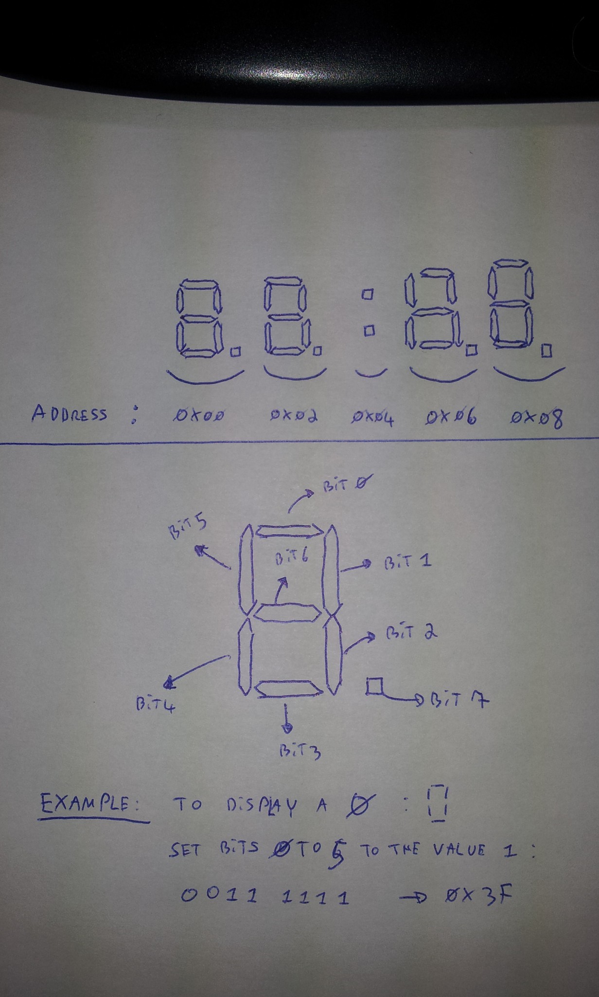
After reading the datasheet and poking around, I figured how to control the display myself, without the LedBackPack library. Here is a picture of my findings :![]()
Each 7-segments of the board is located at a specific register. The first 7-segments is at the register location 0x00, the second at 0x02 and so on. To light on or off specific segments of a given 7-segment item, you send a carefully crafted byte at its register address. Each bit of this byte indicates whether the corresponding segment must be on or off.Let's do an example :
I want to send a command to the display controller. Its I²C addres is 0x70, so I write :Wire.beginTransmission(0x70);
For this display controller, I want to light some segments of the 7-segments item located after the colon sign. Its register address is 0x06, so I write :Wire.write(0x06);
For this 7-segments item, I want to display the character 'H'. I thus must lit the segments number 1,2,4,5 and 6. I must create a byte with the corresponding bits set to 1 : 0111 0110 or 0x76. So I write :Wire.write(0x76);
And finally, I commit the command by writing :Wire.endTransmission();
Don't forget this last line after each I²C command ! I discovered that two I²C commands inside a single transmission worked fine for me, but with three commands I ended up with a garbled display.
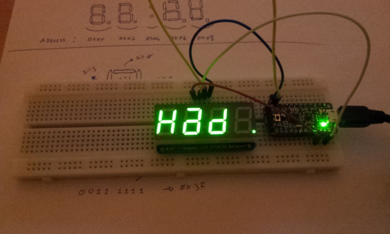
And so, here is my display saying 'Had' in honor to Hack a day :![]()
I'm now more confident to use the Wire library and try to get the FM transmitter working. However, recompiling and uploading a sketch each time I want to test a new I²C command is not fun. So I'm now the proud owner of a Bus Pirate. That should ease things a bit ;) -
The joy of soldering
12/07/2014 at 21:36 • 3 commentsThis afternoon was placed under the sign of solder.
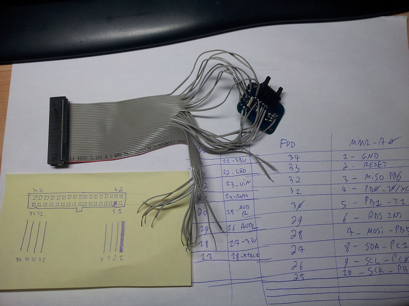
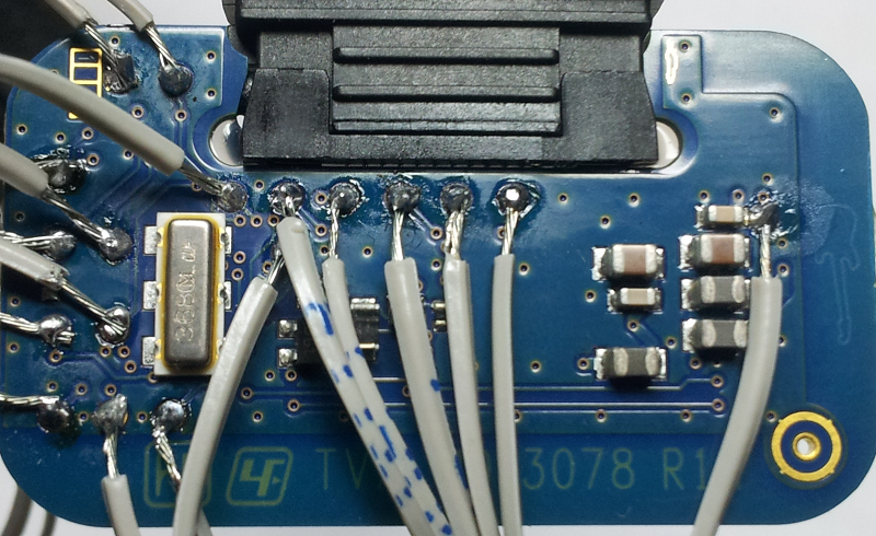
The FM transmitter has a lot of test points but I need a way to hook them up to the Trinket. I do not want to solder wires directly to the Trinket and to the FM transmitter. I prefer to use a breadboard.So, I need wires that can be easily soldered to the Trinket while being easy to connect and disconnect to a breadbord. I tried using jumper cables but they were difficult to solder. My solution was to reuse an old floppy disk cable.
The individual wires of the floppy cable can be easily soldered to the test points. Male-male jumper cables can then be connected to the floppy IDC (?) connector on one end, and to the breadboard on the other end.I took my old 25W Velleman soldering iron out of its dusty drawer. I cut the floppy cable, separated the individual wires, stripped and pre-tinned them. I also pre-tinned the test points. You can see the result here :
![]()
I'm not very happy of my soldering job. Some wires are barely covered by solder, many solder joints have a matt finish. I hope to get some feedback and tips, so I share my bad soldering job in all its high resolution glory here :![]()
I probably should flood this with hot glue to strenghten the connections.
I tripled checked the connections with a continuity tester and everythink was OK and there were no short circuits. I connected the board to my phone and it worked properly. Finally, I wanted to use an seprated power source to test the board.
The board uses a LP2985 power regulator. It takes about 4V from the phone and outputs 2.8V to the board. The datasheet states that the input voltage can go up to 16 volts. Good news, it means that I can be quite careless about the input voltage :-) As a final test, I connected a 5V power source between the Vin and the Gnd pads, and the led blinked !
While my soldering iron was still hot, I soldered the headers of the Trinket. I guess Adafruit's board are pre-tinned and pre-fluxed because it went surprisingly well and I ended with nice and shiny solder joints.
I guess I'm now ready to explore the wonderful world of I²C ;-) -
The joy of incorrect specifications
12/02/2014 at 22:15 • 2 commentsIt's nice to have a fun idea that seems doable (see my previous log entry), but now I need to be a little more concrete. All I have for the moment is an Arduino Uno, so I need to order a Trinket pro. But wait !? There are two flavors : 5v and 3.3v ??
And so starts the endless stream of questions : which one do I buy ? What is the voltage of the FM transmitter ? Does it matter ? Can I mix voltages ? What about i2c ?
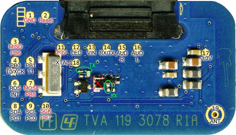
A look at the FMBerry project page shows the following picture :
![]()
It seems that the MMR-70 works on 3.3 volts and so is the Raspberry Pi. I should probably order the 3.3v Trinket. But can I use my 5 volts Arduino in the meantime ? Maybe, maybe not.
I found that 5v and 3.3v hardware cannot always be connected together unless the later is "5 volts tolerant". A mere 1.7 volts out of spec might fry the hardware. I also found that some magic device called a level shifter can convert the voltage between two i2c systems. But beware, some shifters are not compatible with i2c ...
So at this point the plan is to buy a 3.3v trinket, wait for the package to arrive, and stop worrying about this voltage stuff.
Not so fast.
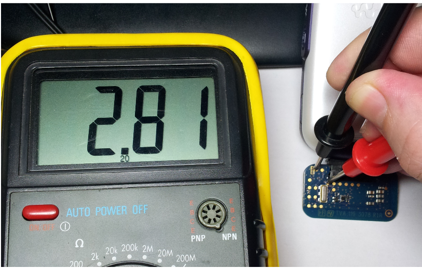
I happen to own an old Sony-Ericsson mobile phone compatible with the MMR-70. So I decided to hook it up and check that it runs on 3.3v. I was not pleased with the result :
![]()
... ... ... 2.8 volts between ground and pin 11 ... Not 3.3v as the photo with the labelled test points stated ! And so starts the endless stream of questions again.
But in the end I guess it's not so problematic : after all, the FMBerry project works and uses a 3.3v RasPi without problem.
I think I will order a 3.3v Trinket pro and a level shifter just to be sure, but still try to connect the Trinket and the MMR-70 directly.
-
The joy of ignorance
12/01/2014 at 16:53 • 0 commentsThis is all new to me and, to be honest, I'm not prepared. However, I think the project falls into the 'plausible' category :
- The MMR-70 FM transmitter is controlled via i2c. The trinket can speak i2c. Check
- The audio input is plain old analog. The trinket has analog outputs. Check
- Arduinos can output wav files and use SD cards. I guess the trinket can do the same. Sort of check
- If the previous item does not work, I can ditch the wav approach and generate the melody with square or sin waves. Backup check
The rest are just details; huge, unexpected, devil-hiding details.