Been a while since logging, because Christmas.
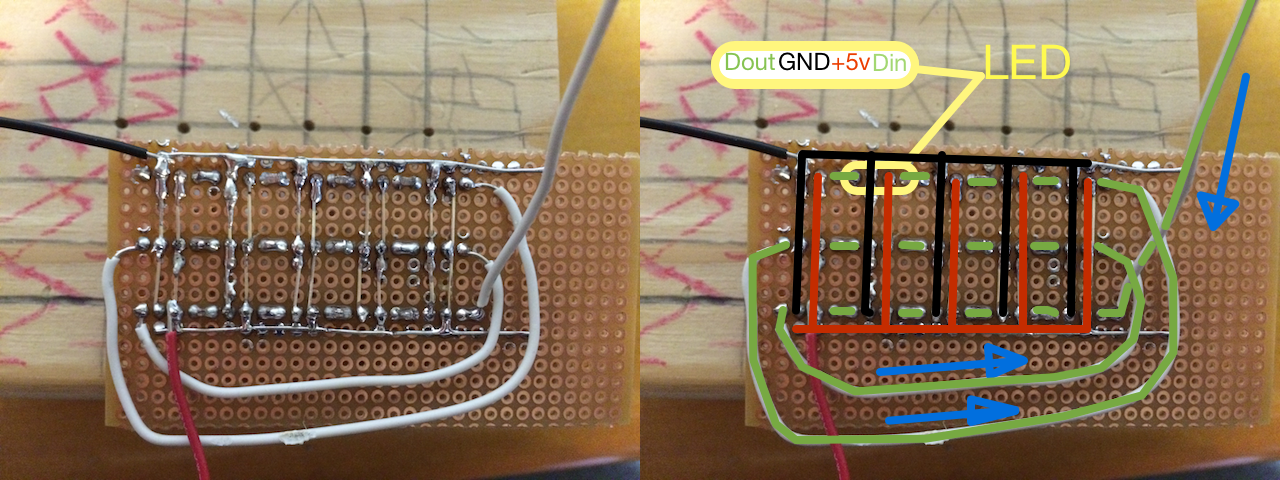
Anyway, I got the full matrix wired up and settled. I'm writing code now, but here's a picture of how I'm wiring everything up.
On the left is an image of the back of the matrix, but if you think that looks confusing, try soldering it! So I drew some hints onto the image on the right to give an idea of what's actually going on.

There are basically three "busses" at work here. The red bus is carrying +5v, the black bus is ground/earth, and the green bus is the data bus. The way the NeoPixels work is by daisy chaining the LEDs together via the Data In/Out pins, which are the outer pins. Each LED takes power and ground for itself. Data comes in from the green wire that goes off-screen to the upper right, and goes right-to-left through the bottom row of LEDs, where it comes out and is brough back to the right side and put into the second row of LEDs, and so on for the third row.
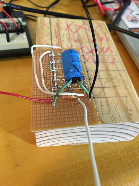
The next picture shows the finalized matrix, with a capacitor across the power and ground busses to protect the LEDs from inrush current when the circuit is first powered up, and a small resistor inline with the incoming data line to protect the microcontroller in the first LED (This forced me to move the incoming data line to be before the resistor). I simply *have* to find a smaller cap!

 Korishev
Discussions
Become a Hackaday.io Member
Create an account to leave a comment. Already have an account? Log In.