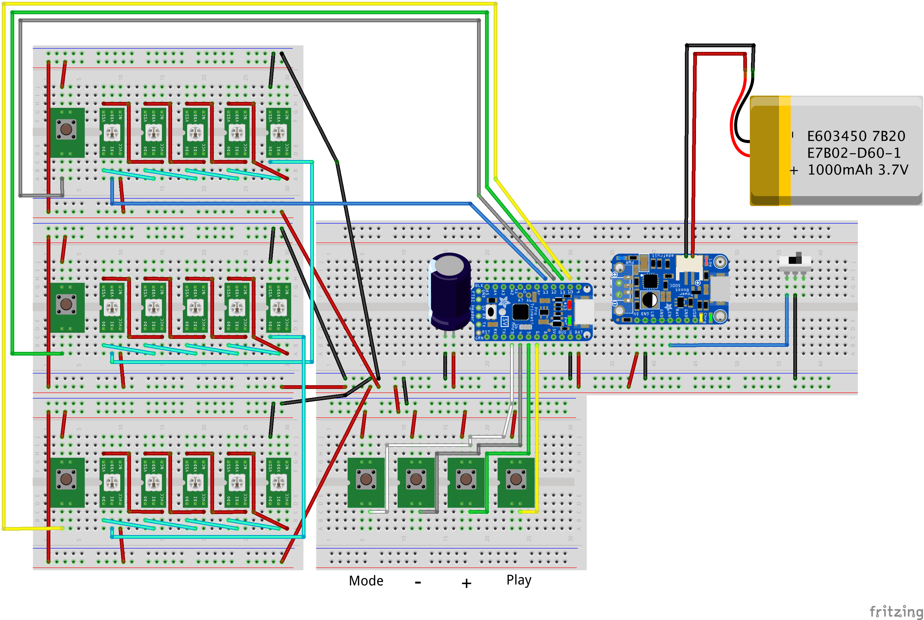
I noticed when I was posting that last log that I had an image of a matrix wired up, but the Fritzing diagram didn't match. I *had* updated the Fritzing, but hadn't posted the log. This image should be closer to what I actually soldered:

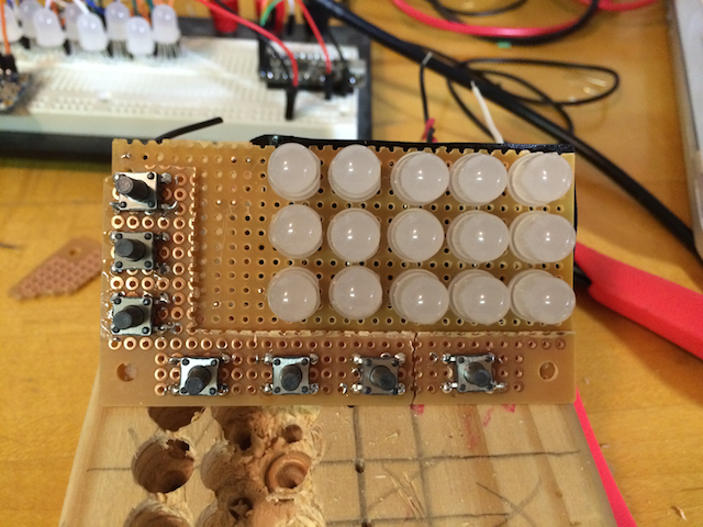
And here's a picture of my (broken) perfboard with buttons on it, as it will be mounted on the LED matrix:

I didn't realize the tac switches were surface mount. Oh well, just makes it a bit trickier.
 Korishev
Discussions
Become a Hackaday.io Member
Create an account to leave a comment. Already have an account? Log In.