Kris Winer
-
Another Zoo Denizen Arrives...
07/16/2018 at 18:01 • 0 commentsJuly 16, 2018
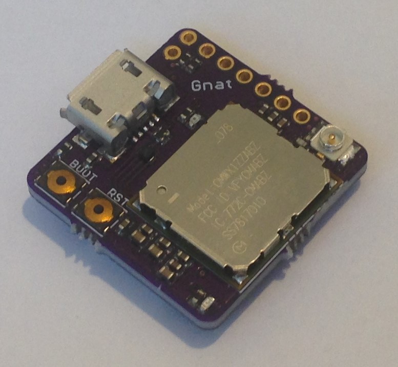
I thought the LoRa SensorTile (23 mm x 23 mm) was about as small as I could go using the CMWX1ZZABZ LoRa module but the Gnat at 20 mm x 20 mm is 3/4 of the area of the LoRa SensorTile.
![]()
![]()
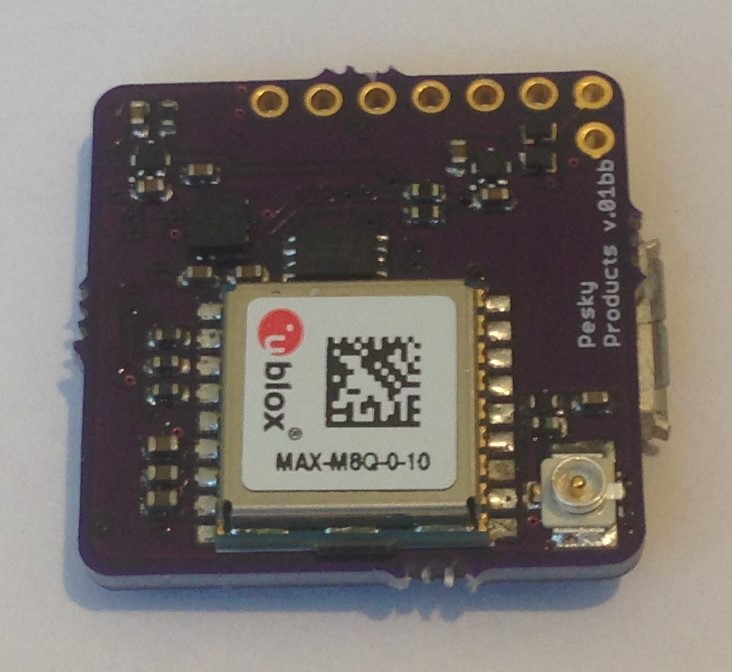
The Gnat uses the same Murata CMWX1ZZABZ module with STM32L082 32 MHz Cortex M0+ host and SX1276 LoRa radio, of course, and includes the smaller U-Blox MAX M8Q (sibling of the CAM M8Q on Cricket) as concurrent GNSS engine. There is a BMA280 accelerometer for wake-on-motion/sleep-on-no-motion control of the GNSS engine and four GPIOs exposed at the board edge (2 digital/SWD ports and 2 analog ports) but no battery charger, SPI flash, BME280, VEML6040 or the other ~10 GPIOs of the LoRa Sensor Tile or Cricket devices.
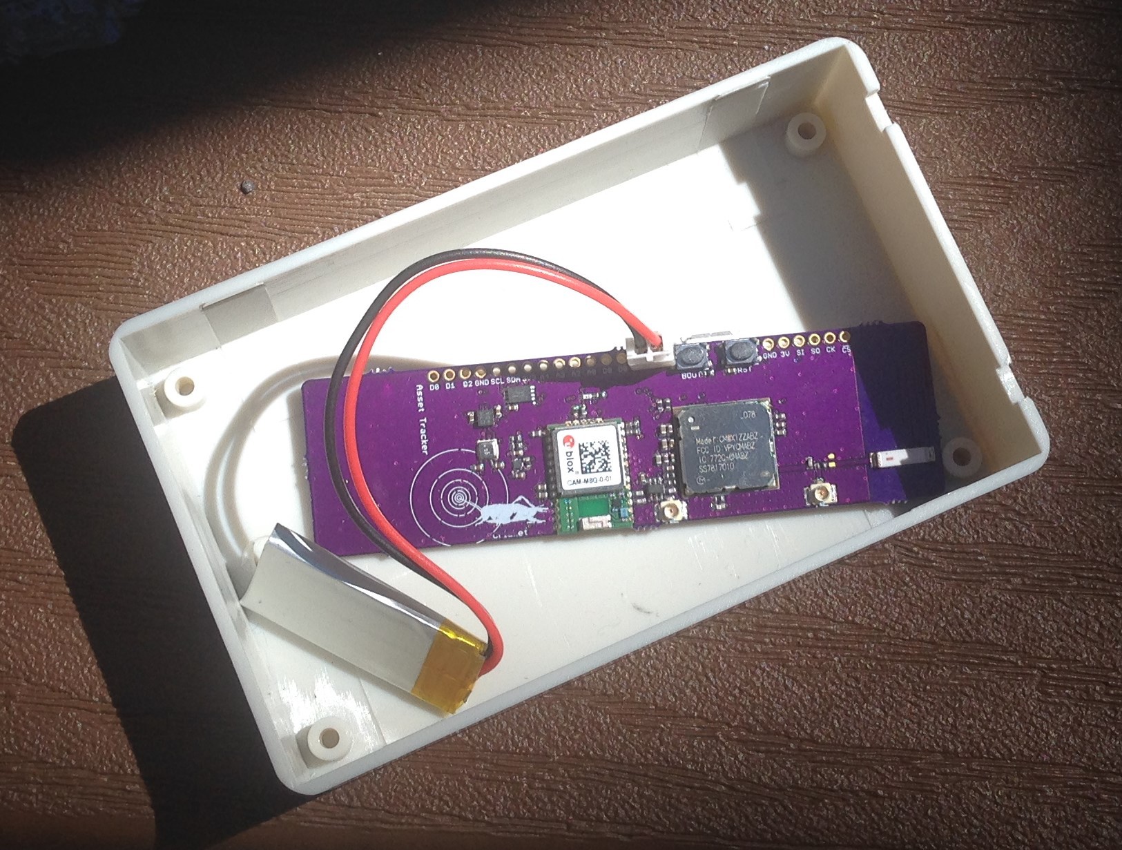
The MAX M8Q requires an active antenna since the internal chip antenna is absent and the ground plane of the Gnat is simply to small to support a chip antenna solution anyway. The CMWX1ZZABZ requires a whip antenna like the Cricket and LoRa SensorTiles do, although I am experimenting with a longer (80 mm x 23 mm) version of the Cricket that has 1) a chip antenna for the CMWX1ZZABZ like the Grasshopper uses and 2) an extended ground plane (71 mm from 46 mm in the Cricket) to increase the sensitivity of the CAM M8Q chip antenna.
![]()
I am testing the power usage now to see if I can get as good performance out of the chip antenna as I do with the active patch antenna. If this longer design works well enough, I might have a small production run made. It is very convenient in some applications (animal tracking, for example) to use an asset tracker that requires no additional antennas attached to the board.So Gnat is a (slightly) reduced-capability mashup of the Cricket and LoRa Sensor Tile devices in a form factor that is approaching the limit of what can be done to shrink the size of any device using the CMWX1ZZABZ module. It is useful for those applications that require accurate location tracking with periodic reporting via LoRa(WAN) but in the smallest weight and form factor (volume, really) possible.
-
Third Cricket Power Test
03/27/2018 at 03:07 • 0 comments03/26/2018
Just finished the third Cricket power test. Like the last one, I am reading/logging sensor data every minute and broadcasting LoRaWAN updates every 10 minutes. I am also using a low duty cycle of one GNSS fix every two hours like the last time, and a high duty cycle of once per minute when motion is detected. This occurs ~once per day manually. Both tests started witha fully charged 105 mAH LiPo battery.
The key variable is the GNSS fix accuracy EHPE, which was either 10 meters (minimum practical value) or 50 meters (a reasonable low-power value. EHPE sets the cutoff for ending the satellite acquisition/tracking and entering power-saving sleep mode):
EPHE hours average current number of fixes rms location accuracy
10 196 536 uA ~110 ~ 5 meters
50 327 321 uA ~180 ~ 15 meters
So with a single AA-sized LiSO2Cl 3.6 V, 2600 mAH low-self-discharge battery the Cricket would last:
202 days at EHPE of 10 and 338 days at EHPE of 50.
This time could be longer if the low duty cycle frequency were to be increased to three or four hours, which makes practical sense because the ephemeris data goes stale after about four hours. So three or four hour fix update is a sensible criterion for the long cycle.
Overall battery life will depend on the amount of motion experienced by the device; the more motion the more fixes per day and the less the battery lifetime. For a 2600 mAH battery, total number of fixes will be limited to between 2700 (EHPE of 10) and 4400 (EHPE of 50). Of course, one could always just use two 2600 mAH batteries in parallel to get out well past one year ;>
-
New Device Added to the Zoo
02/25/2018 at 18:52 • 2 comments02/25/2018
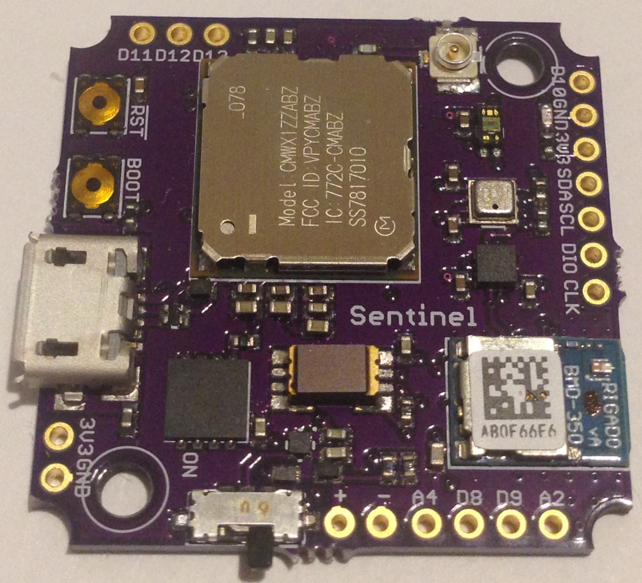
The Sentinel is a purpose-designed utility board for safety and security applications including such things as remote monitoring of the environment, motion detection, and human presence detection, etc. It uses the CMWX1ZZABZ module as host and includes a BMD-350 slave nRF52 for BLE over UART serial bridge. The idea of the BLE slave is to act as a local interface with safety or security personnel via the beacon function as well as back up for the main LoRaWAN communication interface.
![]()
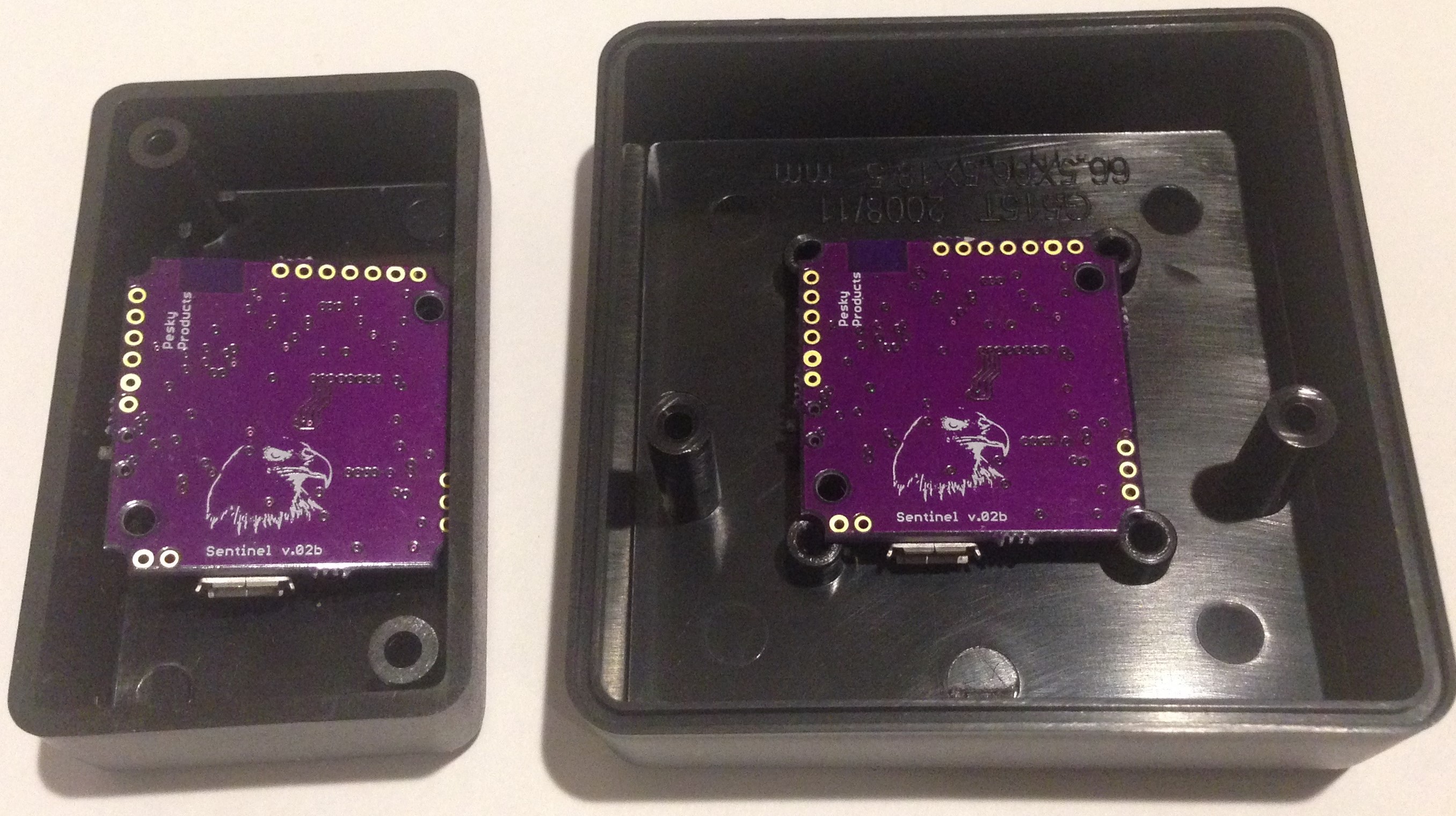
The Sentinel is intended to be battery-powered and the 150 mA, 3.3V NCV8170 LDO uses just 500 nA to provide board voltage regulation. The Sentinel has many of the same sensors as the LoRaSensorTile including BME280 pressure/temperature/humidity sensors, BMA280 accelerometer, VEML6040 RGBW ambient light sensor but adds the CaliPile (TPiS 1S 1385) IR presence/motion sensor for human presence detection. The Sentinel also has an 8 MByte SPI flash for holding multiple programs or data logging. All of these components are ultra-low power allowing the Sentinel to sleep with ~10 uA current, wake periodically or when a sensor threshold is crossed (via interrupt), and remain "on-guard" for years on a single AAA battery.The Sentinel pcb is designed to fit into two off-the-shelf plastic boxes, either a 2.5-inch square box from Bud Industries or a 2.4 x 1.4 inch Hammond box.
![]()
The pcb is designed with all components on one side and mounted close to the box face for easy access for the indicator led, ambient light and presence sensors via drilled holes in the box to the outside. The holes can be covered with transparent shields or cellophane tape to provide a barrier to excessive moisture. There is enough room in the boxes for one or more small batteries. In most cases, using a 3.6V booster and a single AAA battery would be sufficient for years of service. The boxes could be mounted using a strong magnet or velcro, etc depending on the application. It is an inexpensive and convenient packaging solution that allows for rapid deployment and change of location to fit the need.
Periodic LoRaWAN transmissions would be used for passing state information and alerting to threshold conditions but BLE, with its greater throughput (~1 kByte/s), could be used for large-scale transfer of data stored on the SPI flash memory. The BLE beacon would be configured to sleep most of the time and wake periodically. Upon detection of a smart device for pairing, such as a smart phone or tablet carried by a security guard or safety inspector, the Sentinel could pair, exchange the proper authorization codes, and upload more extensive stored data to the smart device and download changes in configuration, etc.
Intended deployment would be construction sites, manufacturing and utility complexes, basically anywhere humans are now required to monitor safety and security conditions. Rather than replacing humans, the intent is to augment human eyes and ears with a device that is always "on watch" for conditions out of the ordinary and able to report over long distances that human assistance is required.
-
Second Cricket Power Test
02/18/2018 at 18:31 • 1 comment02/18/2018
I am in the middle of my second Cricket Asset Tracker power test but I already have some interesting results.
Firstly, I used the fact that the BMA280 accelerometer has two interrupts and a quite sophisticated interrupt engine to set up "wake on any motion" on one interrupt and "sleep on lack of motion" on the other. The BMA280 remains in low power mode 1 (drawing ~6 uA on average) and in this mode wakes up every second to sample the accelerometer. If it detects a change in acceleration greater than a defined slope threshold it wakes up. If it is already awake and detects less than this threshold it goes back to sleep, activating the appropriate interrupt to let the host know which state it is in. The interrupt handlers simply set a flag and wake up the host like so:
void myinthandler1()
{
  BMA280_wake_flag = true;
  STM32L0.wakeup();
  Serial.println("BMA280 is awake!");
}

void myinthandler2()
{
  BMA280_sleep_flag = true;
  STM32L0.wakeup();
  Serial.println("BMA280 is asleep!");
}
Then in the main loop I manage the BMA280 interrupts like so:
    // use BMA280 wake and sleep motion detection to detect motion state
    if(BMA280_wake_flag == true)
    {
      BMA280_wake_flag = false;      // clear the flag
      InMotion = true;               // set motion state latch
      BMA280.activateNoMotionInterrupt();                                                                // Re-enable BMA280 no motion interrupt
      attachInterrupt(BMA280_intPin2, myinthandler2, RISING);
    }

    if(BMA280_sleep_flag == true)
    {
      BMA280_sleep_flag = false;    // clear the flag
      detachInterrupt(BMA280_intPin2);                                                                  // Detach the BMA280 "Go to sleep" interrupt so it doesn't spuriously wake the STM32L4
      BMA280.deactivateNoMotionInterrupt();
    } /* end of sleep/wake detect */
This detaches the noMotion interrupt when the BMA280 is sleeping and re-attaches it when the BMA280 wakes to save a bit of power and avoid false positives. It also sets an InMotion flag for use by the rest of the main loop program. This is a little clunky and I can probably make this more efficient. I did it this way simply to make clear the logic for myself and get the Cricket to behave the way I wanted.
The next bit of magic is the two TimerMillis callbacks:
void callbackNoMotionActivity(void)
{
  GNSS.wakeup();
}


void callbackInMotionActivity(void)
{
  if(InMotion)
  {
   InMotion = false;
   GNSS.wakeup();
  }
}
The first simply wakes up the CAM M8Q at a low frequency, in this test set to once an hour. The second is called every minute but only wakes the CAM M8Q if motion has been previously detected. In other words, I want the CAM M8Q, which is the big power hog on the board, to get a fix infrequently when the asset being tracked is stationary and to update the asset position more frequently when it is in motion. Since it takes a good fraction of a minute to get a hot fix in challenging conditions, a minute for the high frequency period seems reasonable. And since the ephemeris downloaded from satellite is good for four hours, three or four hours seems a reasonable period for the low frequency update. here I chose one hour just to make sure I would get a lot (relatively speaking) of data.
The last bit to making this scheme work is the CAM M8Q sleep criterion:
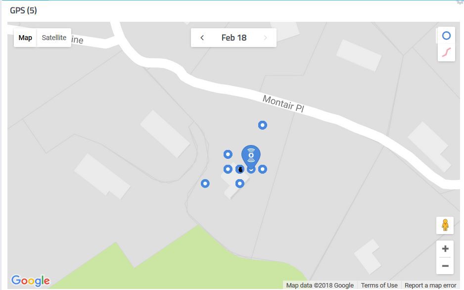
         if(EPE < 100.0f) {
            Serial.println("***GNSS go to sleep!***");
            GNSS.sleep(); // once we have a good location fix put CAM M8Q to sleep
            callbackLoRaTx();  // update dashboard/backend via LoRaWAN
         }
I am using the quality measure EPE (estimated position error) as a sleep criterion such that once a fix is obtained with an EPE less than 100 the CAM M8Q goes to sleep, to wake up either an hour later or whenever motion is detected. The value of EPE is arbitrary but there is a tradeoff. If I use a small EPE threshold, it will take longer to achieve a fix and I will use more power. And conversely, if I make the EPE too large I will get fixes that wander all over the place. The value of 100 gives this kind of result (I am using the CayenneLPP dashboard to capture and display the data):
![]()
You can see my house in this Google maps view and the cloud of GNSS fixes over a 12 hour period (once per hour) with the actual location of the Cricket Asset Tracker marked in black. Cayenne supports three-byte GNSS data meaning the LSByte is cutoff and the effect is to remove the fine position variations below about 20 feet. The row of four dots including the black-marked one represents four different fixes where the longitude is the same but the latitude varies by one bit out of 18. In fact, all but two of the points vary by just one bit. Not sure what happened to the other two, unless the DoD is still playing with GPS in the Western US.
So this is acceptable performance for the purposes of this test but I might want to tighten up the sleep criterion to get more accuracy at the cost of more power usage. We'll see...
In the mean time, I am at day four of the test using a 105 mAH LiPo battery and I expect the test to continue for at least another week. I take the Cricket for a 20 minute walk once a day just to exercise the fast frequency capability and get a more realistic power curve. Everything is being recorded on Cayenne LPP and the on-board SPI flash memory. I project the test will consume an average of ~400 uA, or ~10 mA per day. This might drop to ~3 mA per day with a low frequency period of three or four hours. One year on a AAA battery is the goal.
For many of the applications I have in mind, the asset will be stationary most of the time if not all of the time and the key to success will be detecting and alerting to motion in a timely manner.
Update 2/28/18
The second Cricket power test completed today. The asset tracker was configured to read BME280 and VEML6040 sensor data and battery level every minute, log to the SPI flash every minute, send the latest data via LoRaWAN every ten minutes, and obtain a GNSS fix every hour unless the BMA280 detected motion, then the GNSS fix rate was once per minute (described in detail above). The GNSS fix was determined to be obtained once the EPE (estimated position error) fell below 100, then the CAM M8Q would go back to sleep until the next wake period.
EPE of 100 is rather low resolution for GNSS and the results were usually a cloud of points on the CayenneLPP map mostly covering my house with an occasional outlier or two, so not bad. But this needs to be tightened up for actual asset tracking.
The asset tracker spent most of the time sitting outside on my back deck table or inside on a window sill if it was raining (enclosure is not waterproof). Once a day on average I took the asset tracker for a walk to get the mail or down the block to make sure about once a day the “in-motion” threshold was triggered and extra GNSS fixes were required. This is to mimic the actual use case of tracking items that are expected to be stationary most of the time and where it is important to know when they are being moved as well as generally where they are.
Anyway, the test lasted 14 days 6 hours on a fully-charged 105 mAH 1S LiPo battery so average current of ~307 uA. This exceeds expectations since this means at this configuration and use rate the asset tracker would last about one year on a single 3.6 V, 2.6 AH Lithium Thionyl Chloride (AA-sized) battery.
Next test (just started) is to double the long-frequency duty cycle to two hours (ephemeris data grows stale after four hours) and halve the accuracy criterion to EPE = 50.
I will report on the results of this test in about two weeks.
-
First Cricket Power Test
02/09/2018 at 22:46 • 0 commentsCompleted first integral power test of the Cricket Asset Tracker using a fully-charged 150 mAH 1S LiPo battery, gathering BME280 and BMA280 sensor data and logging same to SPI flash once per minute using the RTC alarm as a timing interrupt, sending same data plus longitude and latitude to a LoRaWAN network (the Things Network) via TTN gateway every ten minutes, and acquiring a new fix from hot start every ten minutes. I know from testing the LoRaSensorTile under more or less the same conditions that the average power usage of everything except GNSS is about 50 uA, so the 150 mAH LiPo would last 125 days except for acquiring GNSS fixes.
The GNSS engine (CAM M8Q) was set up to wakeup every ten minutes using a millisecond timer, acquire a 3D fix, then go to sleep again until the next wakeup. So in addition to the average current usage a key performance parameter is the average time to hot fix (TTHF). This will depend on a lot of factors. In this test, I am using the external (active) antenna with an 18 mm patch antenna I bought on Aliexpress instead of the internal chip antenna embedded in the CAM M8Q. The active antenna requires ~10 mA more power in use but also lowers the TTHF, so for GNSS-signal challenged environments like indoors on my work desk as in this test, it might be a good tradeoff.
In the end, the test ran successfully for just over three days, or 72.5 hours. I received the first LoRaWAN data packet on TTN at 10:46 AM 2/6/18 and the last at 11:10 AM 2/9/18. This means the average current draw was ~2.1 mA and the inferred average time to hot fix was just under 38 seconds.
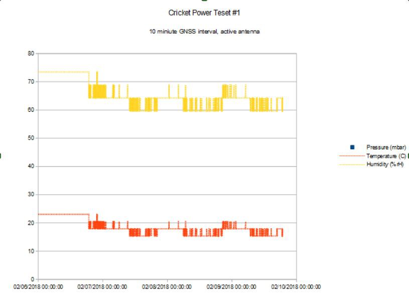
I got the full data log on the 8 MByte SPI flash, here is an example of temperature and humidity over the three days:
![]()
I made some mistakes on the first run. I logged GNSS time instead of RTC time so even though the pressure and humidity, etc data changes the times are the same for each ten minute interval instead of incrementing properly when using RTC time. That is why the data look "spiky". I also forgot to read the GNSS altitude variable so these were logged as all zeroes, not very useful.
But the first test of the Cricket Asset Tracker is a success, everything worked and the power figure is very good. 2.1 mA at 10 minute intervals in a challenging (indoor) environment is a pretty good place to be. This means under these same conditions I could expect to get ~1100mAH/2.1 mA ~22 days on a single AAA battery at this duty cycle. Every ten minutes is too fast for slow moving objects like a bull dozer on a construction site and too slow for rapidly moving ones ike bicycles and cars.
The ephemeris data downloaded from acquired satellites is accurate for about four hours and has to be re-read after this time so a practical upper limit to the acquisition duty cycle is four hours. A practical lower limit is once per minute if in challenging conditions it takes a good fraction of a minute to get a hot fix. In practical asset tracking, the duty cycle would have to be balanced between the competing goals of power usage minimization and tracking accuracy.
The art , then, of a practical asset tracker is to adjust the duty cycle of the GNSS fix acquisition to the tracking problem at hand by acquiring a fix infrequently when the device is more or less stationary and more frequently when the device is in motion. That is the reason why there is an accelerometer on board Cricket and making the GNSS engine motion aware is the next task.
-
Practical LoRaSensorTile Power Usage
01/24/2018 at 02:57 • 0 commentsWith the availability of the CMWX1ZZABZ-078 Arduino core I have started to write application firmware for the various devices with embedded CMWX1ZZABZ-078 modules and test peak and average power usage as well as sleep current.
Grasshopper sleep current is 2.1 uA, LoRaSensorTile 12 uA, and Cricket Asset Tracker 14 uA.
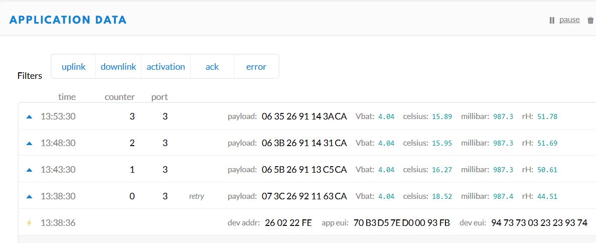
First test of the LoRaSensorTile in use as an edge node casting BME280 and battery voltage data to TTN every five minutes
![TTNdata]()
shows peak Tx of 33 mA and average power (at 3V3 input) of ~50 uA. This is with all sensors active (sensor reads once per minute) but the SPI flash is not selected (trying to figure this out now) so I am not actively writing data for logging, but this will affect the average power usage only slightly.
So ~50 uA is about 1.2 mAH per day so with a small 3V3 booster the LoRa SensorTile should last a couple of years on a single AAA battery.
-
Initial drop of (alpha) Arduino core
01/21/2018 at 02:16 • 0 comments1/20/2018
Located here. Here is a more or less complete how-to to get going with this STM32L0 Arduino core. Just follow the instructions and choose the Grasshopper-L082CZ board in the board manager instead of the Ladybug-L432. I have modified Simon's excellent tutorial below to make it specific to the Grasshopper board:
If you haven't already installed the latest version of the Arduino IDE, you should do that now. If you're running Windows, you should choose to top-listed item, Windows installer (instead of the Windows app store). Linux users can follow these instructions, and Mac OS X users can follow these. Whichever OS you're running, please consider donating to the Arduino Project as part of the download!
To get 32-bit Arduino support, go to Tools/Board/Boards Manager ... (top of the Boards menu), and select the box for Arduino SAM Boards (32-bits ARM Cortex M3), and click the Install button. Although the Grasshopper is an ARM Cortex M0 board, this step will install the gnu-arm compiler that will work with Grasshopper and other ARM Cortex boards.
Typically, your Arduino folder is in your Documents folder on Windows and OS X, and in your home folder on Linux. Keeping your hardware support and libraries in this folder, instead of in the Arduino IDE installation folder, will ensure that they persist after you download subsequent versions of the Arduino IDE. Next, clone this repository into your Arduino/hardware folder. Create a directory called Arduino/hardware/STM32L0 and extract the core into the STM32L0 folder. Rename the core folder to STM32L0. You should end up with the core in the directory Arduino/hardware/STM32L0/STM32L0. Launch the Arduino IDE and under Tools/Boards you should see several new STM32L0 boards toward the bottom of the menu, including Grasshopper-L082CZ.
Finally, you're going to add some OS-specific support allowing your computer to talk to the Grasshopper:
Linux
- Go to Arduino/hardware/grumpyoldpizza/stm32l0/drivers/linux/
- sudo cp *.rules /etc/udev/rules.d
- reboot
Windows
- Download Zadig
- Plugin STM32L0 board and toggle the RESET button while holding down the BOOT button
- Let Windows finish searching for drivers
- Start
Zadig - Select
Options -> List All Devices - Select
STM32 BOOTLOADERfrom the device dropdown - Select
WinUSB (v6.1.7600.16385)as new driver - Click
Replace Driver - Window 7s only:
- Go to Arduino/hardware/grumpypoldpizza/stm32l0/drivers/windows
- Right-click on
dpinst_x86.exe(32 bit Windows) ordpinst_amd64.exe(64 bit Windows) and selectRun as administrator - Click on
Install this driver software anywayat theWindows Securitypopup as the driver is unsigned
Blinky
Of course, no Arduino setup can be complete until you test your board with the beloved Blink sketch! Having launched the Arduino IDE, under Tools/Board choose Grasshopper-L082CZ, and under Tools/Port select the serial port on which your Grasshopper is connected. Under File/Examples/01. Basics chose Blink. Save a copy of this sketch in a temporary location (like your Desktop); Grasshopper led is on pin 13.
Flash the modified Blink sketch, and the little red LED on the Grasshopper should start blinking on and off. If you can't flash the sketch (countdown 10 9 .. 1 FAIL), disconnect the Grasshopper, reconnect it while holding down the Boot button (labeled BOOT), and try again.
Any question or trouble, send me an e-mail at tleracorp@gmail.com.
-
LoRaSensorTile power usage
01/20/2018 at 05:08 • 0 commentsThe LoRaSensorTile has a lot of sensors so the current is no longer dominated by the CPU current alone. I used an ST power monitor to measure the current usage as a function of time for different conditions. The ST power monitor supplies 3.30 V which I applied to the 3V3 and GND inputs of the LoRaSensorTile. The currents reported below might be a bit higher when using a 4 V LiPo battery.
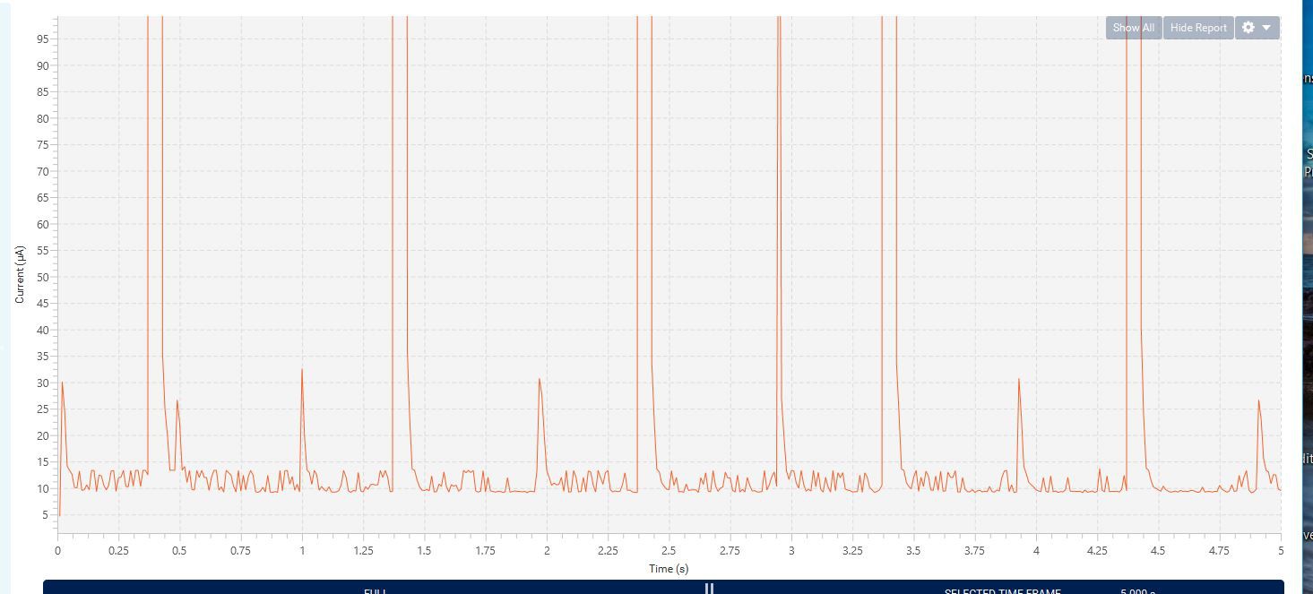
A portion of the current history as a function of time for 32 MHz clock speed is shown here:
![]()
You can see that every second the when the RTC alarm goes off data is read and the led blinks, etc before the STM32L082 returns to the STOP mode, with stop current of ~12 uA; this includes the ~2 uA for the STM32L082 as well as the current drawn by the I2C sensors, battery charger, and SPI flash, which are absent in the Grasshopper.
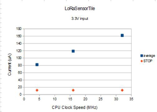
The average current as a function of clock speed is plotted below:
![]()
You can see the advantage of dropping the CPU speed as low as possible when deploying devices in the field. The current used by everything except the CPU is about 70 uA (0 CPU intercept). This means the CPU uses ~92 uA at 32 MHz, ~49 uA at 16 Mhz, and ~12 uA at 4.2 MHz; CPU current usage is proportional to clock speed, as expected. At just over 80 uA average current usage at 4.2 MHz the LoRaSensorTile would last for more than a year on a couple of AAA batteries.
-
Grasshopper power usage
01/19/2018 at 18:59 • 1 comment01/19/2018
Average power usage for an application will depend on what peripherals and duty cycle are chosen, etc but we can get some idea of what ultra-low power means for users of the CMWX1ZZABZ by measuring the power required to perform a simple task, in this case blinking an led, going into stop mode for 5 seconds, then repeat.
Here is the sketch:
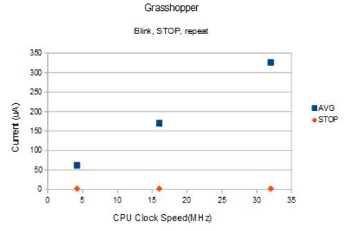
/* LED Blink, for Grasshopper

   This example code is in the public domain.
*/
#include <STM32L0.h>

#define myLed 13 // red led
#define myADC A1

float VDDA, Temperature;
uint32_t UID[3] = {0, 0, 0};
uint16_t adc = 0;

void setup()
{
  Serial.begin(38400);
  delay(2000);
  Serial.println("Serial enabled!");

  pinMode(myLed, OUTPUT);
  digitalWrite(myLed, LOW);  // start with leds off, since active HIGH

  pinMode(myADC, INPUT);
  analogReadResolution(12);

  STM32L0.getUID(UID);
  Serial.print("STM32L0 MCU UID = 0x"); Serial.print(UID[0], HEX); Serial.print(UID[1], HEX); Serial.println(UID[2], HEX);
  }

void loop()
{
  digitalWrite(myLed, HIGH); // toggle red led on
  delay(100);                // wait 100 millisecond
  digitalWrite(myLed, LOW);  // toggle red led off
  delay(1000);               // wait 1000 milliseconds

  VDDA = STM32L0.getVDDA();
  Temperature = STM32L0.getTemperature();

  adc = analogRead(myADC);
  Serial.print("ADC = "); Serial.println(adc);

  Serial.print("VDDA = "); Serial.println(VDDA, 2);
  Serial.print("STM32L0 MCU Temperature = "); Serial.println(Temperature, 2);

  STM32L0.stop(5000);
}
I am also reading an ADC and sending out some serial, but these are typical tasks. How much power is used?
![]()
You can see that the average power usage during the active part of the sketch is almost proportional to the clock speed as expected; the proportionality is better when the constant average power (~22 uA) to blink the led is factored out. This means for most applications you want to run at 4.2 MHz clock speed if you can to minimize power usage. In this case, it takes 62 uA to blink the led for 100 ms and read the ADC every five seconds at 4.2 MHz; USB serial is disabled at 4.2 and 16 MHz.
In stop mode, all state information (SRAM) is retained and after the time out (or upon interrupt when using STM32L0.stop();) the program picks up where it left off. Best practice is to have all sections of the main loop depend on interrupts and leave the MCU in stop mode otherwise. When the Grasshopper is in stop mode, my multimeter reads 2.1 uA. Now that is ultra-low power!
Hackable CMWX1ZZABZ (LoRa) Devices
Useful STM32L082-based devices with embedded LoRa radio modem programmable with the Arduino IDE via USB connector, i.e, hackable.