 Elecia White
-
1Step 1
Of course you'll read all the instructions before you start. Pay special note to step 5 which involves using a dremel tool to cut a board to size.
On the whole tools you will need:
- Soldering iron, fine solder, small wire
- Dremel tool with cutting wheel (or other cutting accessory), mask so you don't breath board
- Hot glue and funtac (or other temporary mounting putty)
- Beepy mode on a voltmeter
- Way to program the MicroView (FTDI cable or the MicroView reprogrammer)
- USB charger for LiPo and necessary connections
- Sacrificial jumper wires
-
2Step 2
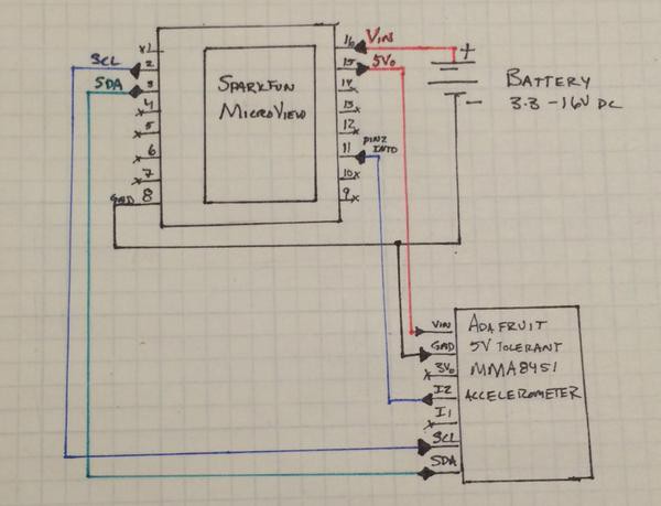
Temporarily wire together the accelerometer and the MicroView:
- Connect SDA and SCL.
- Connect the accelerometer's INT2 to MicroView's INT0 (pin 2).
- Connect ground.
- Connect MicroView's 5V out to the accelerometer's Vin.
- (Powering the MicroView will be the next step.)
![]()
I had some trouble with the accelerometer connections until I soldered them (steps 4-6), they were flaky connections, unhappy with my normal press-fit a header to a solderless breadboard solution.
I did not solder on the header pins that came with the accelerometer, they would be too big in the ring.
If you are skilled at soldering, you may want to go ahead and do that. Otherwise, make sure your accelerometer has pretty good contacts.
-
3Step 3
Program the MicroView, test the code and wiring.
If you got the fancy MicroView programmer board, you can use that. Alternatively, you can use an FTDI cable. Either way, the MicroView getting started page will show you how to wire, power, and program the MicroView. Program it with the Wordy code from github.
Note that the code takes up all available space. You can comment out some words in wordlist.h if you want to add debugging strings (see note there on how)if you want to add debugging strings.
When you finish programming, test the modes work. Be careful of your accelerometer if you haven't soldered it yet.
-
4Step 4
Take it apart to solder wires on the MicroView.
Once everything works, it is time to start soldering the connections. Since I want a ring, it makes sense to use small wires that will stay out of the way.
I tend to strip one end of wire wrap wires, use tweezers to twist it around the MicroView pin, then tack solder on. Strip the other end and make sure you have good contact between the top of the pin and the other end of the wire.
-
5Step 5
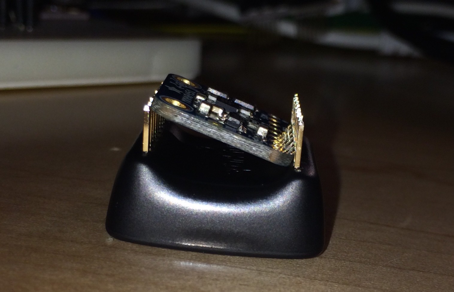
Modify the Adafruit board: it doesn't need mounting holes or a logo.
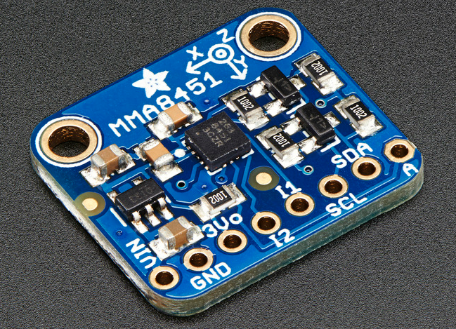
One big problem with this whole project is finding an accelerometer that can withstand the 5V from the MicroView (or even the 4V from the battery) and fits in the MicroView. The Adafruit does the former but not the latter.
![]()
The solution is to use a cutting tool (for me it was a Dremel with cutting wheel) to remove the excess board. You want to leave the MMA8451 for margin but get rid of everything above that.
![]()
I'd never done this and was worried about it. It was much easier than I expected. However, it did kick up a decent amount of dust so I was glad for my safety glasses and breath mask.
-
6Step 6
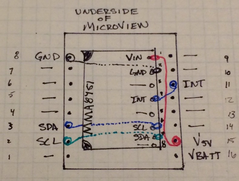
Solder it together. Make a decision about the battery.
Put the accelerometer component side toward the MicroView with the pinholes toward the power side. (Realistically any orientation works, this one made the most sense to me.)
![]()
The dotted lines indicate running those wires under the board. It took a lot of tries for me to get this right, cutting down wires and stripping the ends (ok, I admit, I melted plastic in a few spots where stripping the wire was difficult). And when I soldered the wires on the accelerometer board, it was again a matter of twisting (all of them), then soldering. Then making little spirals to take up the extra wire and add strain relief. Then a hot gluing.
Unfortunately, there was no "picture taking" in there so I only have the end product.
Also, I used the mounting putting between the board and the MicroView, to hold it in place. The hot glue is for the wires more than to keep the board in place.
![]()
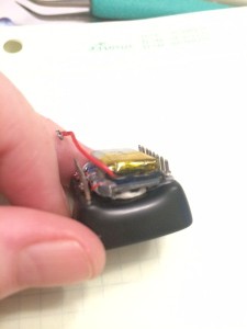
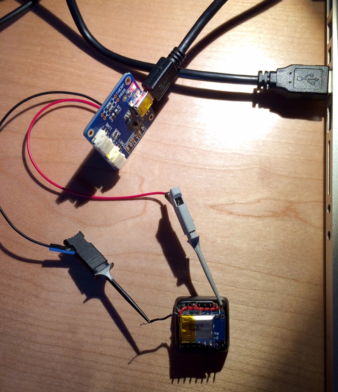
Next, I put my battery on top., again affixed with mounting putty. Note that I clipped the leads on the batter and I soldered the red wire on to Vin on the MicroView but left ground twisted-but-not soldered.
To recharge the LiPo, I take off ground, hook it to my USB LiPo recharger, then clip to power. This is not a good long term solution as the ground wire will eventually break.
![]()
-
7Step 7
Create a ring base. You might start with a standard jewelry finding (some on Amazon).
At this point, the device should work. You only need to make a way to wear it. However, this is a tricky, crafty step. I chose to try many different things, eventually finding a few I liked.
My favorite so far is to use a metal ring base and then add a container on top: a little box made of Sculpey clay. Sculpey is nice because it can be rebaked and sanded. However, it does shrink a little and is infuriating when you get it perfect and then it shrinks just a little too much the oven.
Anyway, I made a box to set the electronics in. (The box is about 150% the size it needs to be but at least it didn't shrink too much.) After I backed the box, I sanded down some space on the bottom to put the ring in.
![]()
Then I used more Sculpey to attach the ring to the box, baked it again, then hot glued from the inside.
![]()
(Note, early attempts to make the whole ring out of Sculpey were failures, the material is really bad at flexing. I had some good luck with cloud clay as it is reasonably flexible. Check the project logs for a look at other things I tried.)
The female connectors in there will be explained in the next step.
-
8Step 8
Put it all together. Hot glue is your friend.
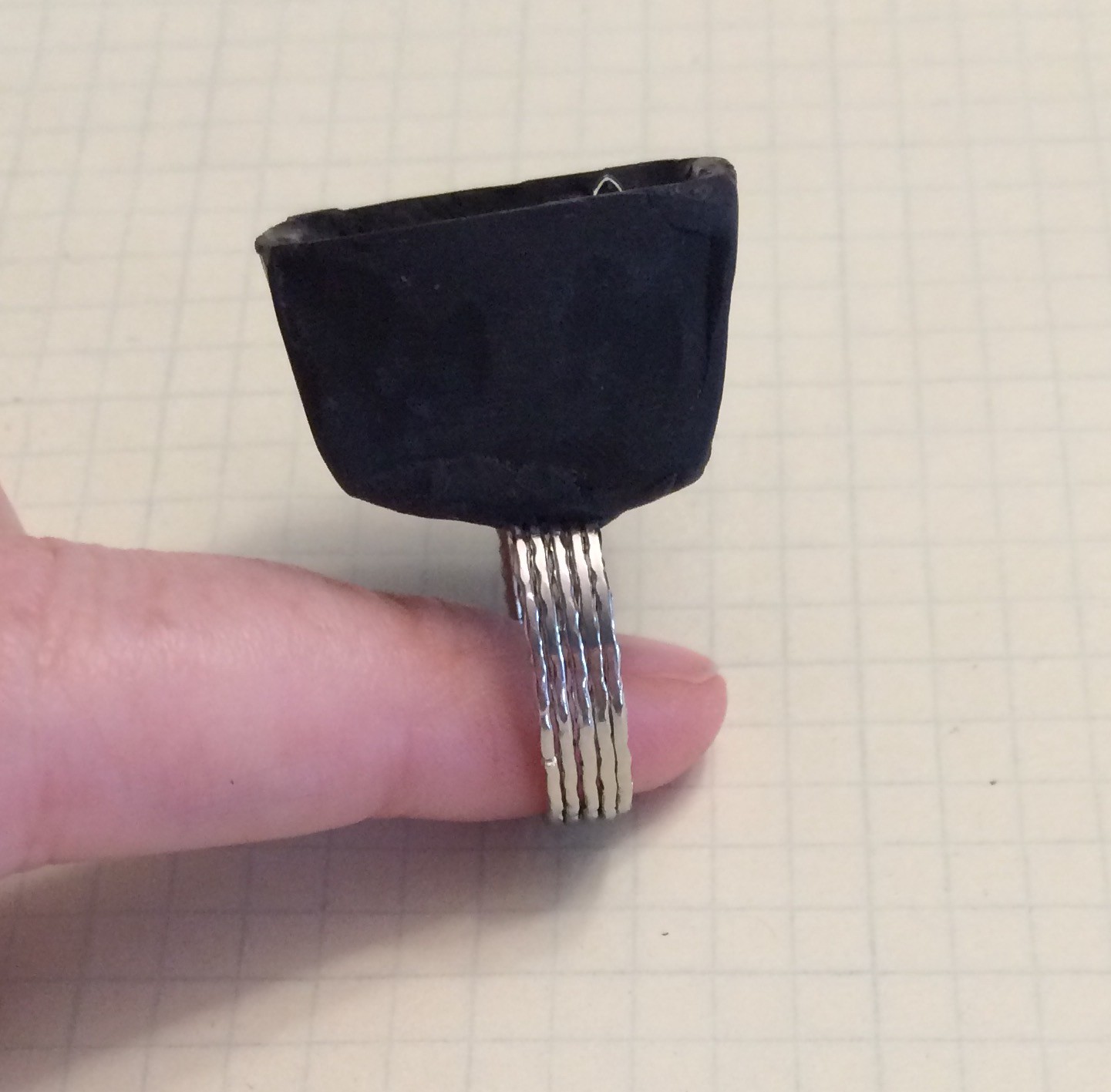
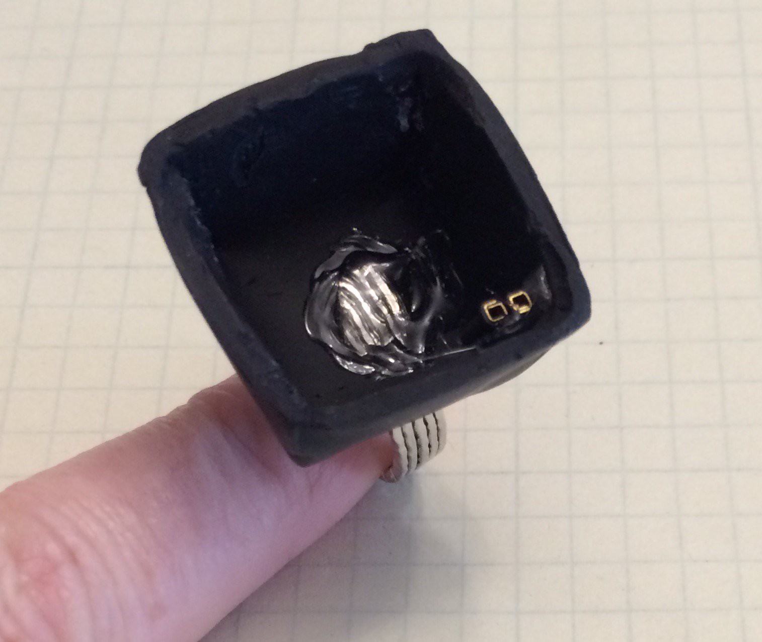
Since my ground wire is press-fit, I needed a good connection. I sacrificed a few jumper wires to obtain about half a centimeter of connector, putting two on every corner of the MicroView's pins. I put a bead of hot glued on each pair, then put the whole thing in the mounting.
When it came out, the MicroView left some of the connectors behind. (I did consider putting the connectors in the Sculpey first but the fitting problem is difficult, this made the system fit while still allowing future improvements.) The connectors still attached to the MicroView were easy to pull off. I'll reuse them when I put it back together.
-
9Step 9
Play with it.
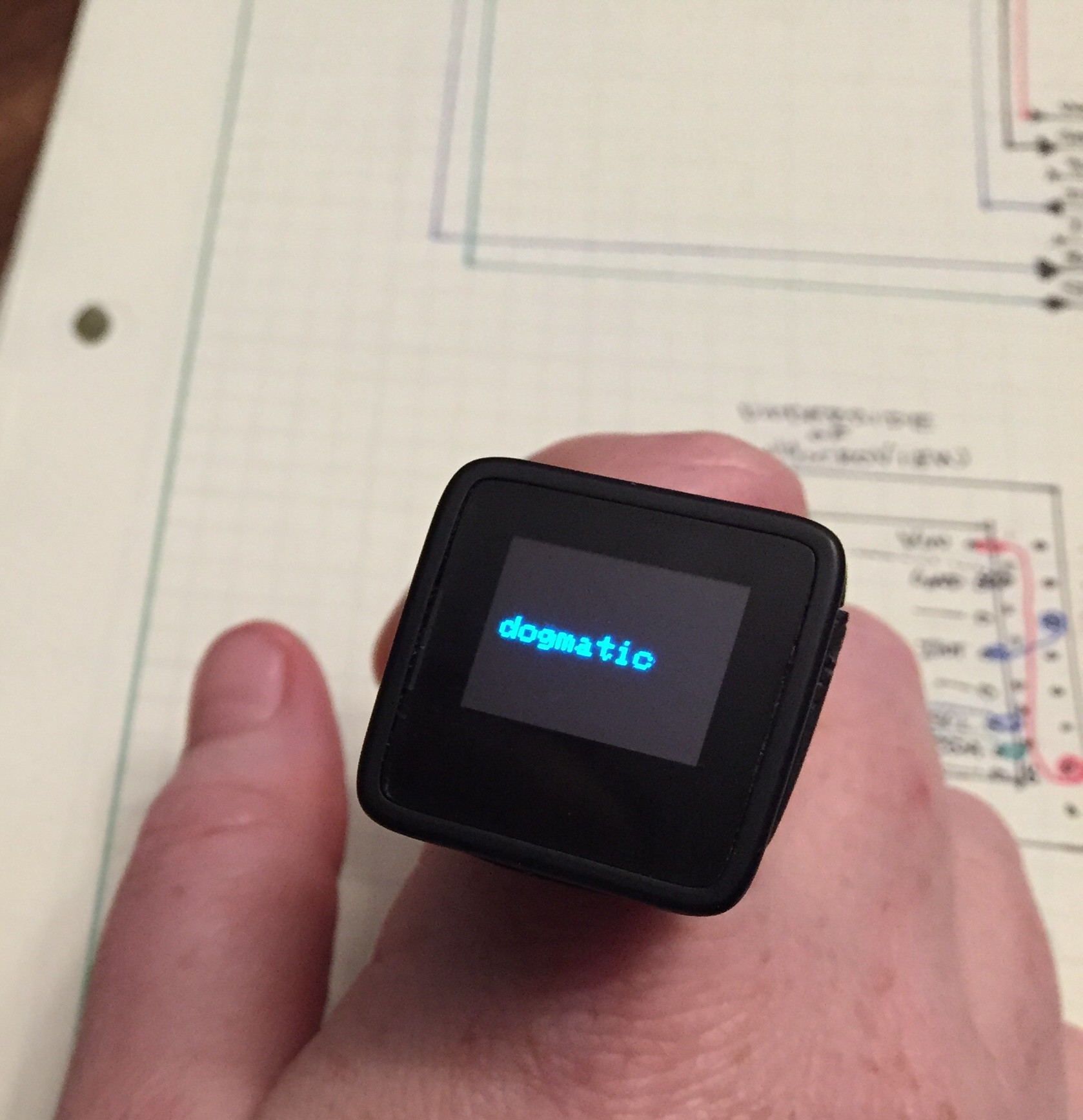
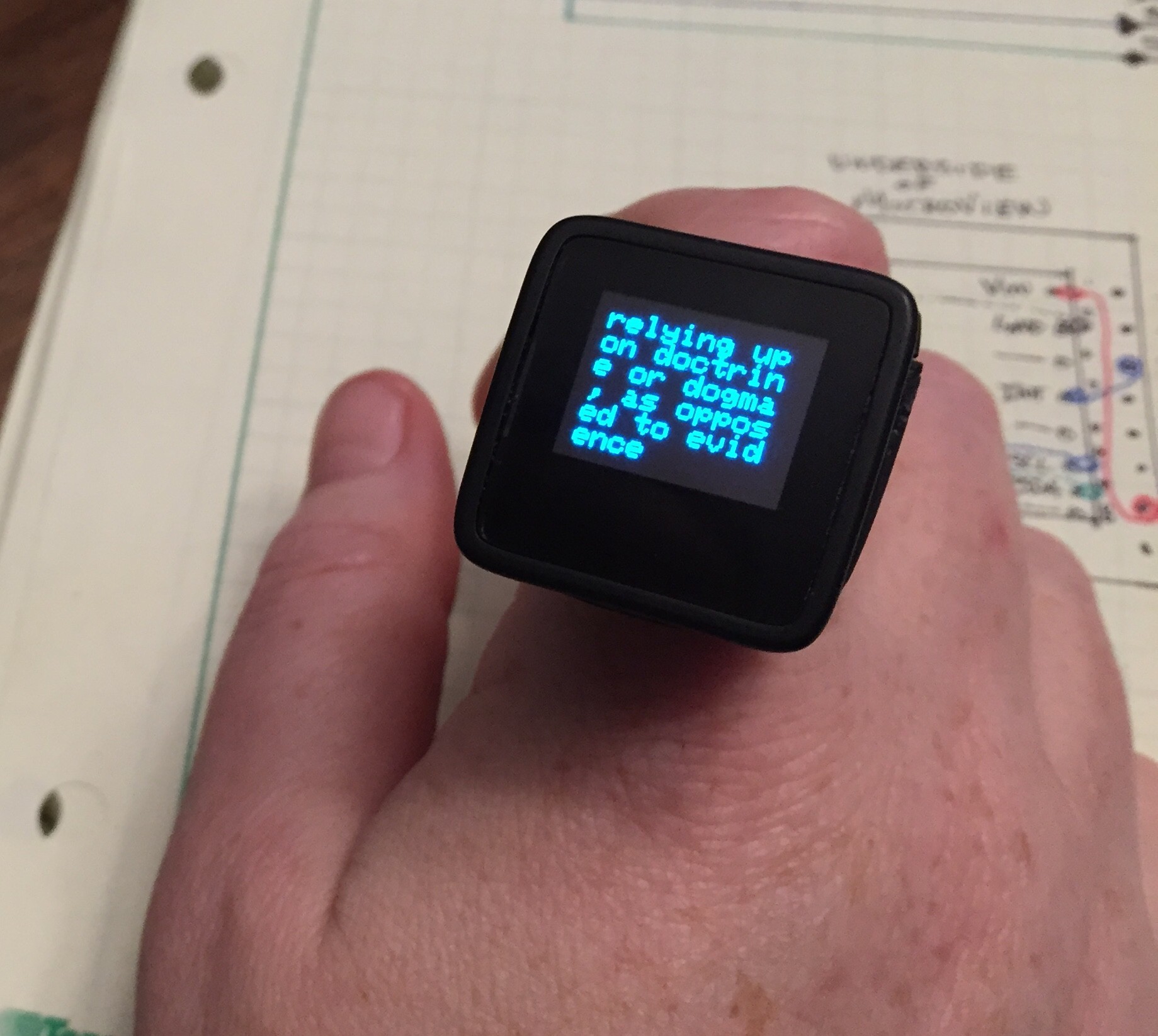
Start with a tap.
![]()
Tap again to get a definition.
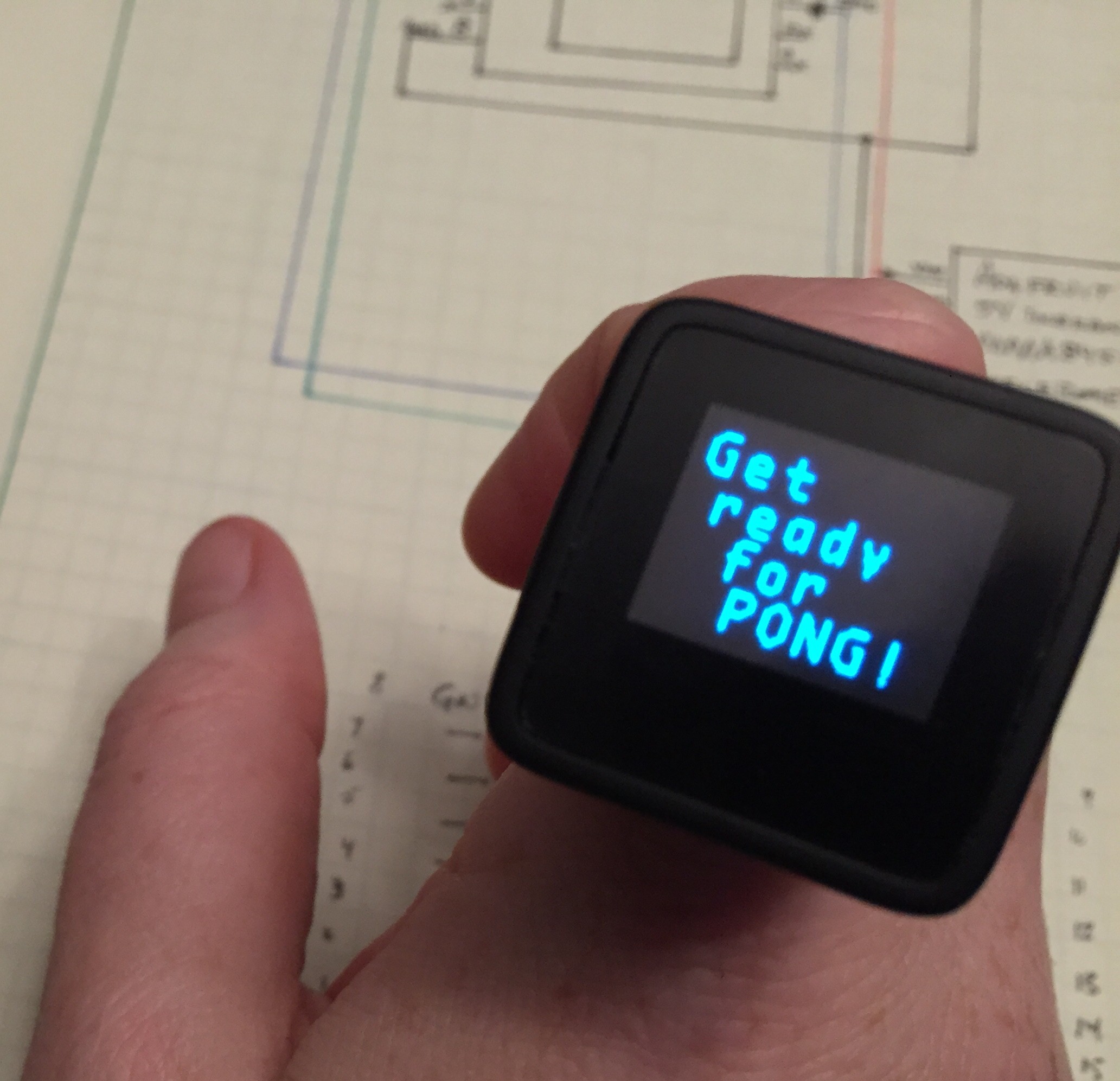
Double tap to play pong (it is a very fast double tap but you can change that in the accelerometer setup if you are willing to read the datasheet).![]()
![]() Once it starts, you are the filled in paddle (on the left).
Once it starts, you are the filled in paddle (on the left).![]() Tilt your hand to move your paddle. It plays to 3 points. You can win, lose, or do another double tap to turn off the game.
Tilt your hand to move your paddle. It plays to 3 points. You can win, lose, or do another double tap to turn off the game. Next, turn your hand upside down and shake.
Another shake (upside down) and you will get a traditional Magic 8 ball answer to your question.![]()
As for air-punches, those are tricky to get. You have to mean 'em or they turn into Magic 8 ball responses. (I may update the code to fix their finickiness.)
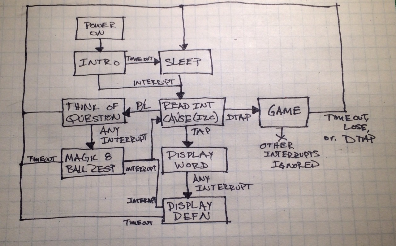
Here is the whole state machine, as a flow chart.
![]()
Wordy
Ring that has interesting vocabulary, plays accelerometer Pong, and answers questions. Implemented on the Arduino-based MicroView platform.
 Once it starts, you are the filled in paddle (on the left).
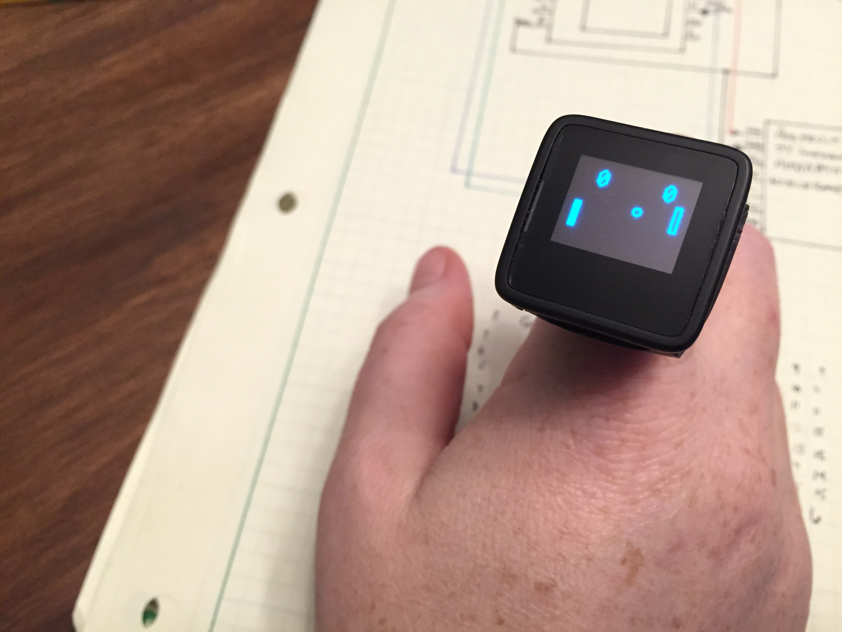 Tilt your hand to move your paddle. It plays to 3 points. You can win, lose, or do another double tap to turn off the game.
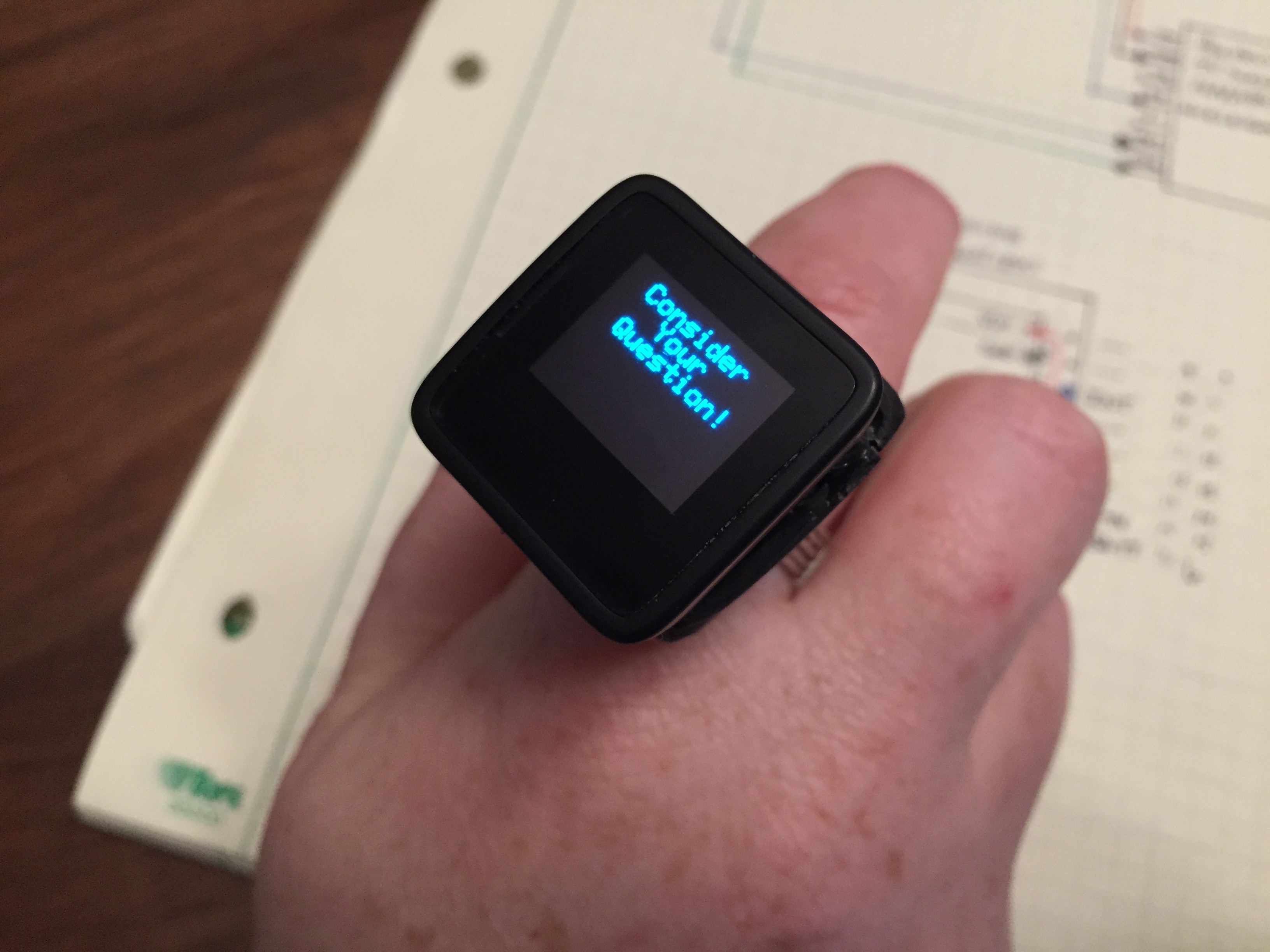
Discussions
Become a Hackaday.io Member
Create an account to leave a comment. Already have an account? Log In.
Are you sure? yes | no