Jac Goudsmit
-
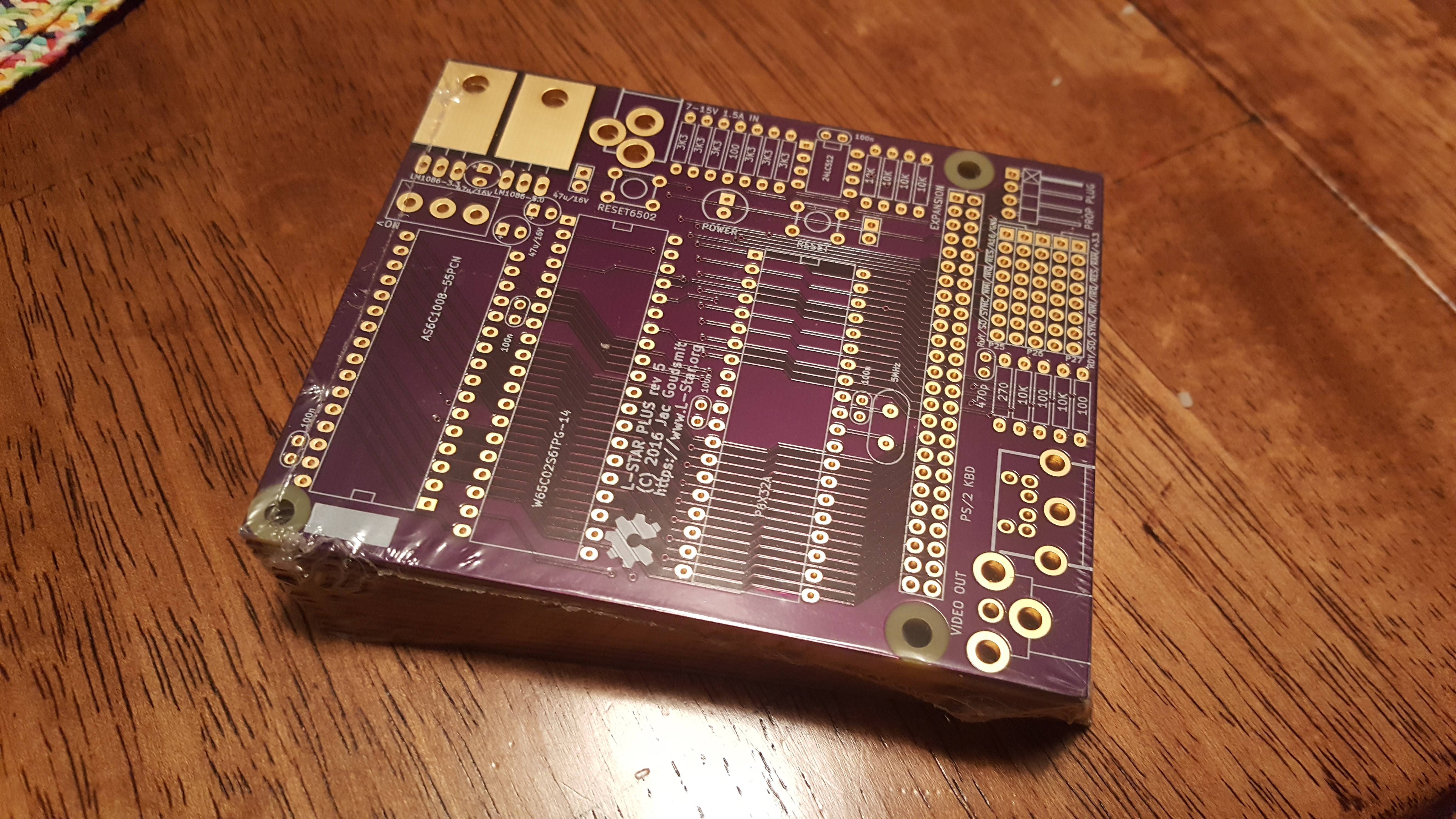
Minimal L-Star on a Breadboard, and KITS ARE BACK!
04/18/2020 at 08:42 • 0 comments![]()
I intended to get this done last weekend for the 44th birthday of the Apple 1 computer (April 11 1976) but unfortunately it wasn't meant to be. After I had put the circuit together, it didn't work at first. The 65C02 that I was using, had given the ghost, possibly because of me being careless with static electricity. I checked all the wiring first (which took a long time) and when everything checked out, I wrote a short program to slow the 6502 clock down to a crawl of 1 Hz or so, and write the INA input register to the screen on every clock cycle. That finally showed that the address bus and data bus were the same on every cycle, so the 65C02 wasn't running.
After I replaced the 65C02 with another, everything worked just like it should, but by then it was Tuesday. Then I got some "distractions" from work and family life, and I could finally get back to it on Friday.
I replaced the instructions section of the project here on Hackaday with instructions on how to breadboard your own L-Star for (probably) less than $50. Have fun!
Oh, and by the way, I got parts for a batch of L-Star Plus kits. It will be back in stock some time this weekend. YAY!
-
L-Star As a SuperCon2018 Badge Add-On
11/05/2018 at 19:27 • 4 commentsApple-1 emulator for SuperCon2018 Badge
I turned my SuperConference 2018 Badge Add-on board into a 6502 computer, so if you're tired of playing Zork on a Z80, you can play Super Star Trek on an Apple 1 emulator.
I didn't win the badge hacking competition, though I think I might have had a good chance to at least be admired on stage if I would have had 5 more minutes with a soldering iron; the add-on was basically working but it was disconnected from the badge because of a wiring mistake that I didn't notice until after all the soldering stations had disappeared.
![]() ---------- more ----------
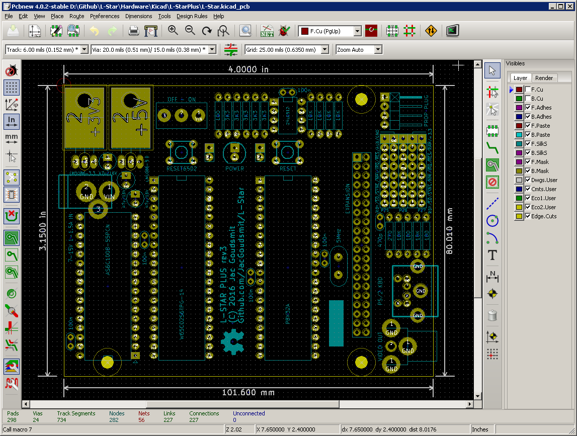
---------- more ----------Layout
![]()
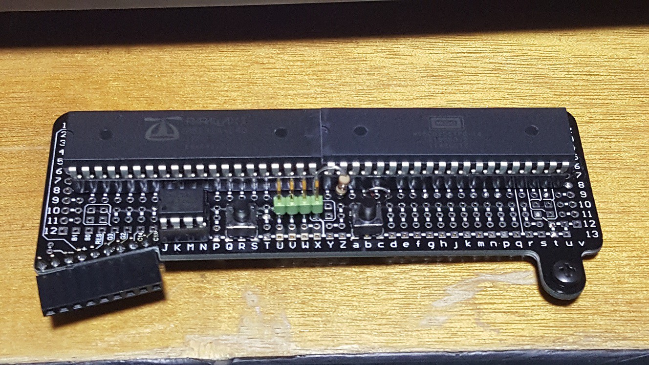
Fitting the Propeller and the Western Design Center W65C02S on the add-on board wasn't easy. The designers apparently didn't have two 40-pin DIP chips in mind when they made up how to connect the islands on the board. There was pretty much only one single way for the Propeller and the 6502 to fit on there, and I knew from the beginning that that would cause trouble, since the chips are right next to each other and everyone knows(?) that most DIP chips are too big to be mounted next to each other like that. There was going to be some filing in my future.
There was not enough space for the 8 pin DIP socket for the EEPROM after I had soldered the two 40-pin chips: it looks like there's an ocean of holes but they're all connected to each other or (by now) connected to the 40-pin DIP sockets. Fortunately the EEPROM has all pins 1-2-3-4 connected to ground, so I could cheat a little and just put it right there on the ground rail.
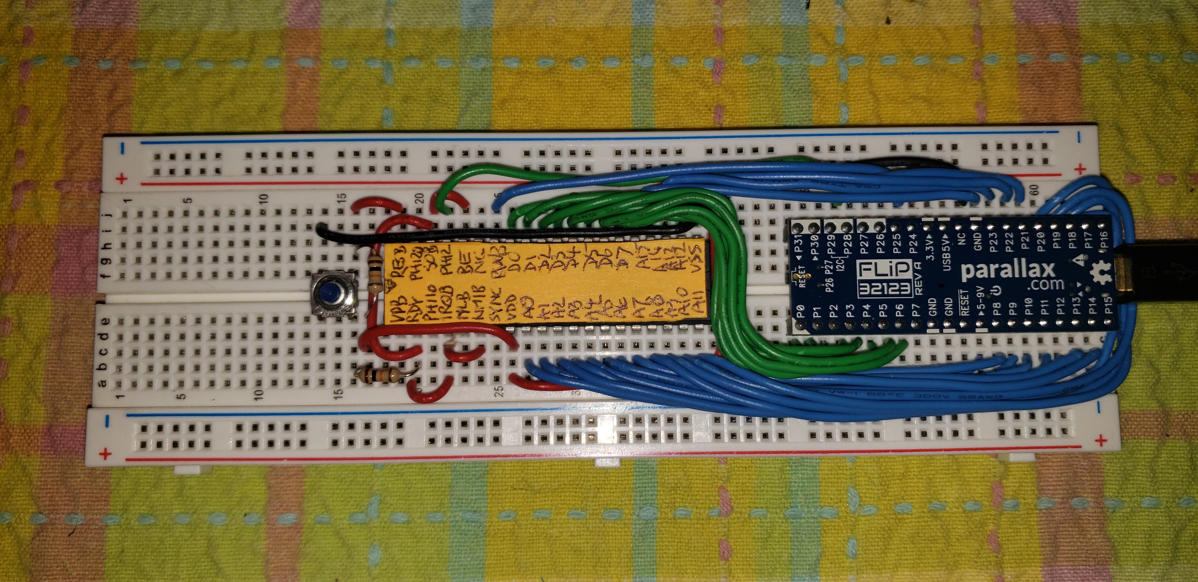
Propeller Bringup
![]()
The badge hacking area at the SuperConference had a nice supply of parts and tools, but unfortunately there were only 3 choices of wire: (1) Too thick and inflexible, (2) so thin that the wire strippers would cut the wire instead of stripping it, and (3) magnet wire.
I decided to go with magnet wire. I had never used that for a hacking project and I don't think I'll do it again. Basically the way you work with it is that you use the soldering iron to melt the insulation where you want to solder it, and this just seems like an incredibly unreliable way of working to me. I didn't have a multimeter to test each connection (I should have brought one, and I did the next day) so I had to eyeball each solder joint to guess if the wire was actually connected and if the insulation was (probably) gone. This made the soldering take a long time and I still found out later that I had one solder joint where the insulation hadn't melted.
I soldered the pin header for the Prop plug on the board in a place where VSS would already be connected to the ground rail. I had to bend my 90 degree connector first; there was no way to mount it in such a way that I could have plugged in the Prop Plug from the side. Oh well.
The photo above is from when I had wired up the Propeller to the EEPROM and the Prop plug. The Badge was acting as power supply. Fortunately the Propeller Tool recognized the Propeller, or I would have aborted the project right there. But writing a program to the EEPROM didn't work at this time.
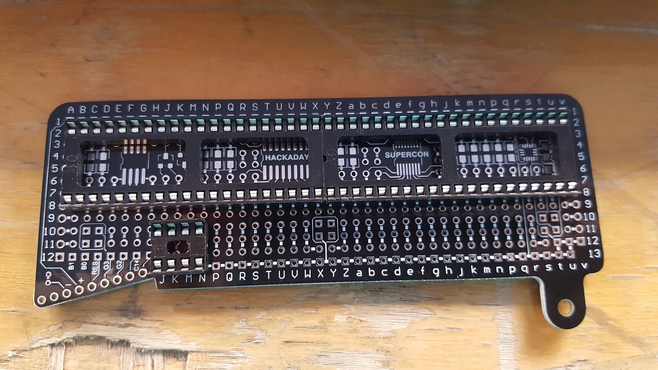
6502 Wire-Up
![]()
As I mentioned, the Propeller and the 6502 didn't fit in their sockets right next to each other. I was trying to scrape the edge off one of my chips with the beak of a side cutter, when another hacker noticed what i was doing, and was friendly enough to ask around for a file. I don't know where he got it and when I was done, he couldn't find the person he got it from, but thanks guys! After I had filed the sides of both chips flat, I could kinda jam them into their sockets.
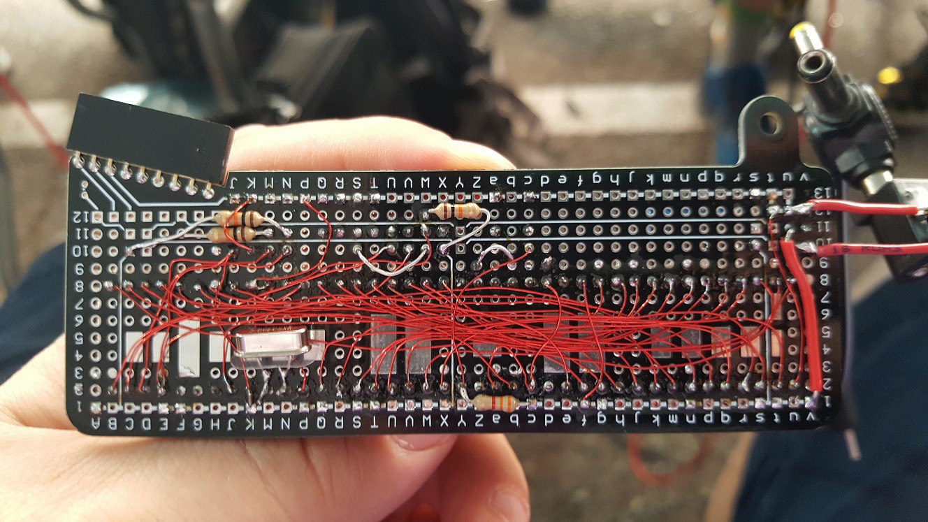
In the L-Star circuit, there are 26 connections between the Propeller and the 65C02S: 8 for the data bus, 16 for the address bus, and R/!W and the clock. There are also two reset buttons (one for the Propeller and one for the 6502).
There are also at least 2 pull-up resistors on the 6502 (one for !RESET and one for all the unused input signals !NMI, !IRQ, !RDY, !SO and !BE). The !RESET resistor went on the bottom but the other one went on top. The signal input pins on the 6502 are all two pins away from each other so I put the wire through the board and then "serpented" it back up and then back down. You can see it between the 6502 and the reset button.
"Final" wiring results
![]()
I already mentioned that the wiring was a lot of work, so let's not waste too much time on describing that, except to say I'm pretty proud of how it looks in the end.
I was trying to figure out why the EEPROM wasn't working, and I thought maybe it was a power supply issue. The badge works on the unregulated power from two AA batteries (3V) and the Propeller is designed for 3.3V. I soldered a 3.3V regulator from my kit onto the board (with an electrolytic to prevent oscillating) and attached a barrel socket via some wires because I saw no way to mount it on the board in a way that would have made it stay attached. I also added a power LED because that way, if anyone asked me what I did with my add-on, I could at least say I added an LED ;-).
That didn't fix the EEPROM problem, but later on I realized that I had mounted the pull-up resistors for the 6502 but not the ones for the Propeller. The I2C circuit with the EEPROM really needs two pull-up resistors and if you want to detach the Prop Plug it's also good to have a pull-up attached to the Propeller reset pin. After I soldered those, I could program the EEPROM. Cool!
In the picture above, I think the only connections that I hadn't made yet were the connections to the serial pins of the badge.
Serial connection to the badge (log all the fails!)
By this time, it was Sunday afternoon and the time when the badge hacks had to be finished and submitted was coming closer. I had been in a workshop in the patio area and I knew there was not going to be another workshop there, so I stayed there and spent some time figuring the code that was in the badge. It looked like it already has most of a terminal emulator, which was used with the CP/M emulator. The code to read characters from the serial port and the UART receive-line and send it to the UART transmit-line and the screen was pretty simple and obvious, and it was also pretty easy to change my L-Star code so that it would use two serial ports instead of a serial port, a 1-pin TV driver and a PS/2 keyboard.
Unfortunately the patio got cleared, and I had to move once again. I found a place to sit in the SupplyFrame building but I couldn't figure out why the serial traffic wasn't working. Then I overheard another hacker say that he had worked on the serial port, so I asked for help. We thought I was overlooking something in the software but as it turns out, my software was okay and I had misinterpreted the schematic and connected my Propeller to the wrong pins on the connector (the two left ones instead of the two right ones). Of course by then the badge hacking part of the conference was about to begin and there was no soldering iron in sight anymore.
Software fixes
So I decided to go home and finish it there. The resoldering of the two wires was a 5 minute job (including getting my soldering station out; I don't have a workbench at home). I was happy to see that my simple terminal-program on the badge seemed to work, but it was spitting out garbage at first. As it turns out, when I modified the code on the Propeller to use 2 serial ports instead of video and keyboard, I had made a copy-paste error and it was programming the badge serial port at 115200 bps just like the Prop Plug serial port. Oops!
![]()
After I fixed it so it used 19200 bps for the badge connection, it kind of worked but the UART receiver on the badge got stuck: It displayed a few characters of the boot-up message of the L-Star program and then nothing. But the buttons on the badge were working fine (I could see that on the PC that was attached via the Prop plug). So I just had to slow things down a little bit so the UART on the badge wouldn't overrun.
My changes in the terminal driver of the L-Star firmware on the Propeller were pretty much copy-paste changes to do the same thing on the badge serial port as on the Prop plug serial port. At first I had changed the function that sends a string of characters so that it would send the string to one port and the to the other port. and when I changed it so it send the characters one-by-one, alternating between the connections, it started working!
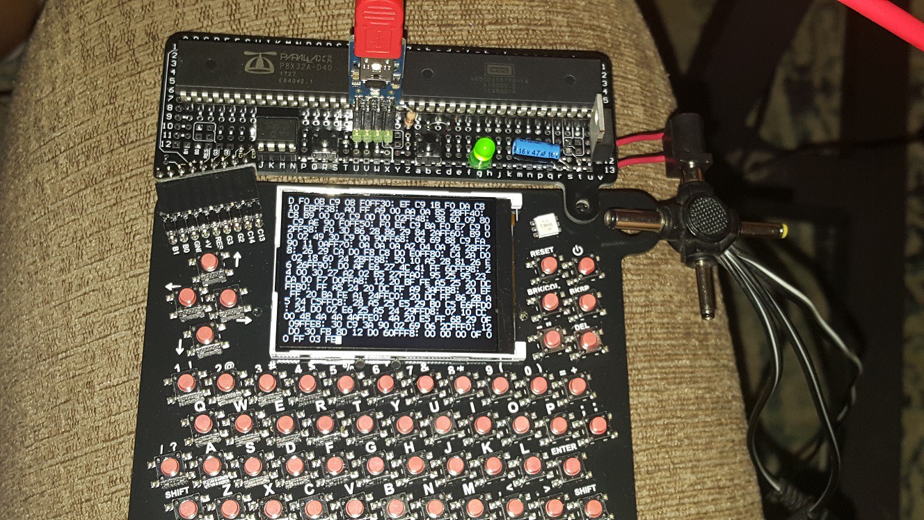
The Apple 1 was now being emulated (with 20KB of emulated RAM space, pretty cool for a computer from 1976), and I could enter commands from the badge keyboard. I could even enter a command that would generate a lot of output and the badge UART didn't get stuck!
Except... the badge and Woz Mon disagreed on when to go to the start of the next line. The badge's opinion was basically "never".
![]()
The firmware of the badge was written with C code in mind, so "\n" (line feed) causes the cursor to move to the beginning of the next line of the screen. But carriage return does nothing.
We could have a long discussion here about what line feed and carriage return are supposed to mean, and what character(s) should be used as line breaks.
The short and good is that the Parallax serial terminal uses Carriage Return as line break, and so does the Apple 1 software (Woz mon, Krusader and Woz BASIC as well as AppleSoft/Microsoft BASIC). So the solution was easy (though not ideal): make the Propeller translate all outgoing carriage returns from to line feeds before they get sent to the badge.
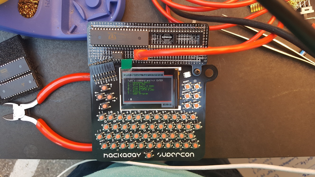
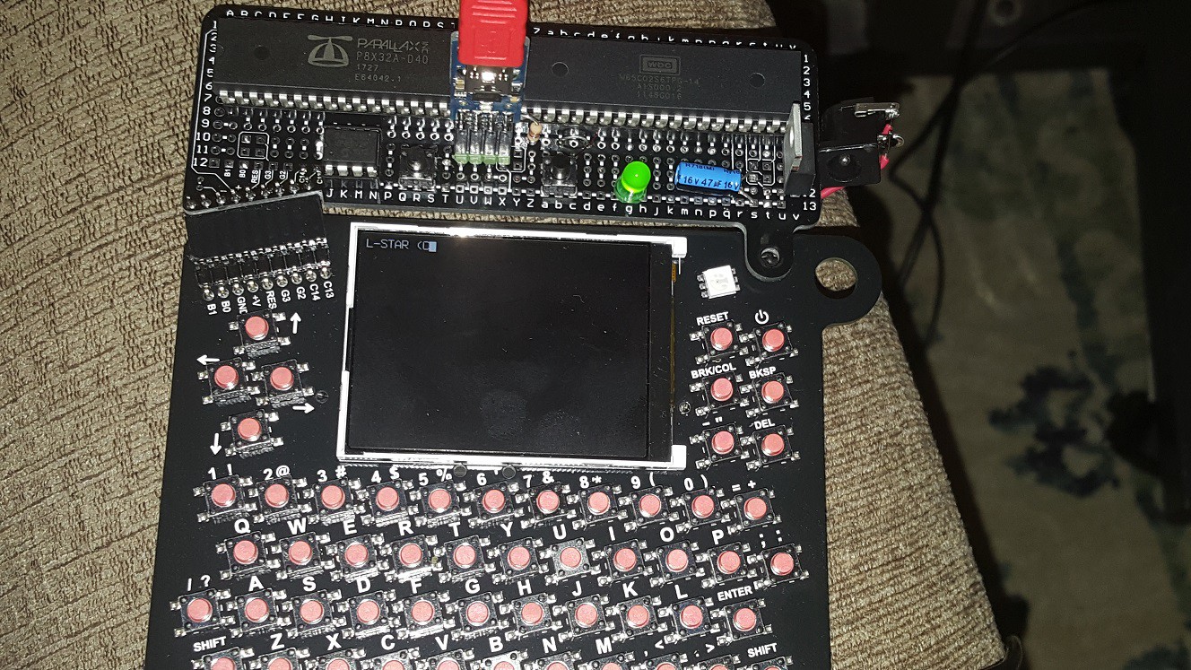
Hello Woz Mon! I'm a badge!
![]()
By the way, I posted a Pull Request to make the one-way terminal in the latest badge software into a two-way terminal yesterday. I also made some changes to my clone of the Supercon badge firmware so that it works more like a terminal: hitting Return (without shift) sends a Carriage Return (not a line feed), there now is a Caps Lock, and you can send all ASCII codes from the keyboard including the non-printable control codes. See https://github.com/JacGoudsmit/2018-Supercon-Badge.
Oh and by the way, I forgot to add a resistor on the RX line of the Propeller, so whenever the Prop plug was disconnected, the PIA emulator thought that it was getting garbage on the serial port to the PC. Sigh. So I had to get my soldering iron out of the garage again and solder one more resistor to my add-on board. Stupid 80-20 rule ;-)
![]()
So the above really is the final version of the add-on wiring.
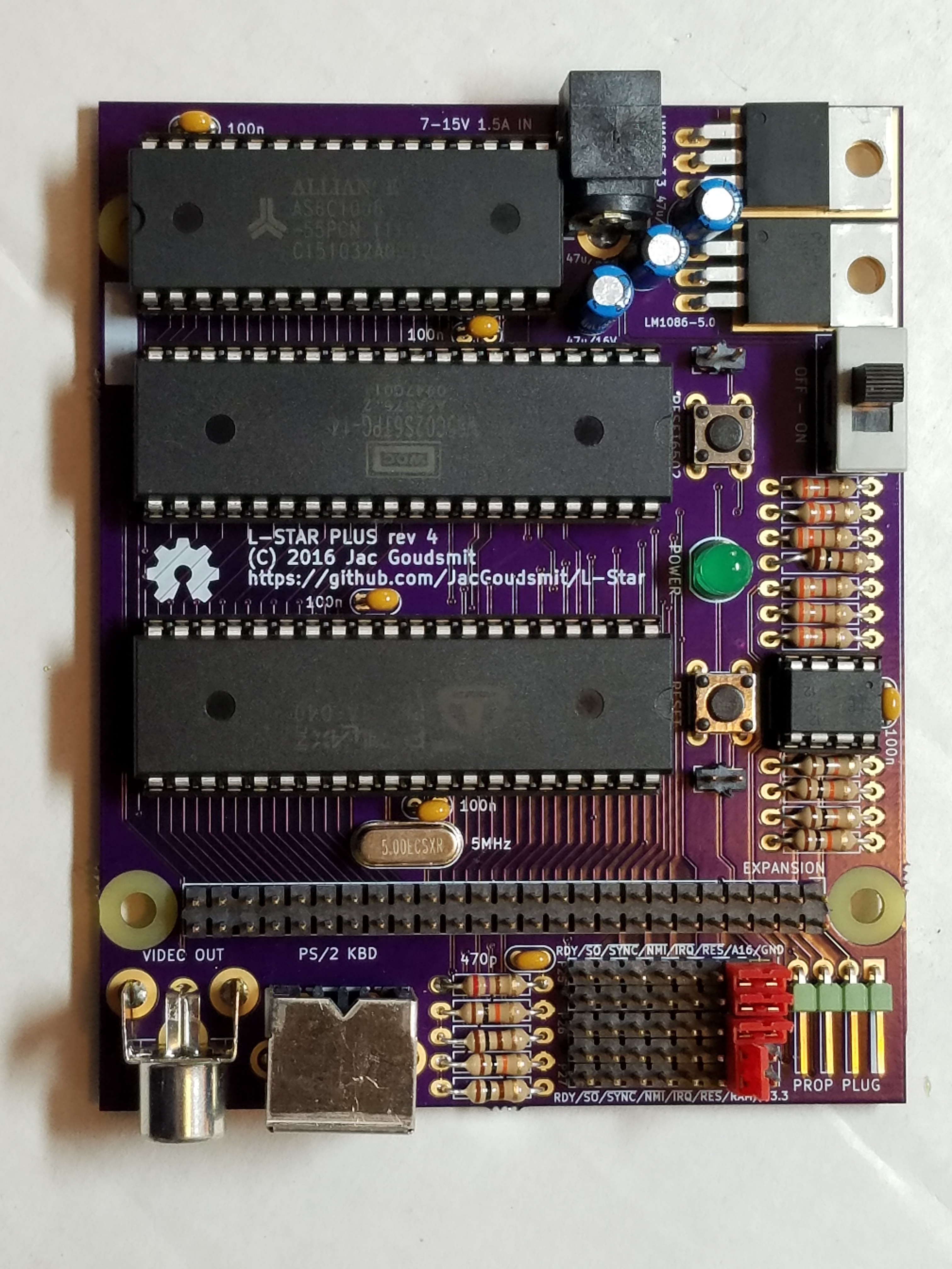
Circuit description
The Supercon badge add-on version is the most basic form of the L-Star project. The Propeller is connected to the data bus, address bus, R/!W (Read/Not-Write) output and the clock input of the 65C02. It's also connected to the Prop Plug (basically an FTDI plug connected to the USB port of a PC) and the badge via two serial connections. And there's an I2C EEPROM that stores the Propeller firmware (which include the Apple 1 ROM). The following is a rough schematic of this minimal L-Star version (I made this on my phone, sorry if it doesn't pass ERC or sanity checks :-).
![]()
The Address Bus and Data Bus take up 24 of the Propeller's 32 I/O pins. An additional two pins are needed to provide the clock (PHI2IN) to the 65C02 and to get the Read/Not-Write (RWB) signal from the 65C02. The clock pin is the same pin as the SCL pin of the EEPROM; the SDA pin is held high during operation so that the EEPROM never gets enabled.
The Propeller generates a 1 MHz clock pulse for the 65C02, and at the beginning of each clock cycle, the 65C02 puts an address on the address bus, and makes the RWB line either high if it wants to read, or low if it wants to write. In write mode, the Propeller reads the data bus and in read mode, the Propeller writes the data bus; this happens during the second half of the clock pulse because during the first half (when PHI2IN is low), the 65C02 doesn't use the data bus.
On the 65C02, the input pins that can be used to interrupt the processor and to influence its operation, are all pulled high via a pull-up resistor. The Apple 1 doesn't use interrupts.
The reset pins on the 65C02 and the Propeller have a button to pull them down and a resistor to pull them up. There are also pull-up resistors on the I2C lines to the EEPROM (otherwise it won't work, see above), and on the RX line of the Prop Plug so that if you unplug it, the input will still be high so the Propeller won't see any incoming traffic.
Propeller Software
As you may know, the Propeller contains eight processor cores called "cogs" which each have a task. For example, one cog lets the 65C02 access the Propeller's internal memory to simulate ROM and RAM, another cog emulates the Peripheral Interface Adapter (PIA) chip, which on a real Apple 1 connects to the keyboard and to the video hardware.
There are two cogs that implement a serial port: one that's running at 115200 bps and connects to the PC via the 4-pin Prop Plug header, the other serial port connects to the badge at 19200 bps. Whenever the PIA emulator gets a byte from the 65C02 to send to the screen, it gets sent to both serial ports. And whenever the Propeller receives a byte from one of the serial ports, it gets sent to the PIA emulator, making the 65C02 think that a key on the keyboard was pressed.
65C02 Software
The 65C02 needs software to run, and the original Apple 1 came with only one small piece of software: Woz Mon. It takes up less than 256 bytes of ROM, and allowed you to inspect and change memory content, and execute programs. That doesn't sound like much, but it was enough to get started! Note: the Woz mon on board of the L-Star was slightly modified; keep reading.
A number of years ago, [Vince Briel] designed a replica of the Apple 1, and sold it online. He made some changes to the original design to make it more affordable. For one thing, there's no such thing as a 256 byte PROM anymore nowadays, so he had to use an EPROM and ended up with a lot of unused space. Plenty of space to add Integer BASIC (a BASIC interpreter by Steve Wozniak) which was originally available as a tape but modified to be used from a ROM.
Another addition was a program called Krusader by Ken Wessen. That program lets you interactively write 6502 and 65C02 code in a line-based editor (the Apple 1 had no cursor keys, it worked like a printing terminal) and convert them to machine language so it can be executed. It also includes a debugger. The Woz Mon code was changed slightly to make it possible to execute Woz Mon commands from Krusader. And Ken also made a change so that backspace works like a backspace. Thanks Ken!
Vince made the ROM image file available on his website, and I've been using it for years for the Apple 1 projects of the L-Star project.on Github. Thanks Woz, Vince, Ken and everyone else who contributed!
By the way, it's also possible to use the version of AppleSoft BASIC (really Microsoft BASIC) that was ported to the Apple 1 in recent years, by changing the ROM file in the Apple1.spin source file, and reprogramming the Propeller.
What's Missing
The circuit has a 64KB EEPROM which has 32K of unused space (the Propeller uses the low 32K) but there's no software on-board to use that space. I have some plans to use it in a certain way, but there are other things that have a higher priority. Also there's no other storage device on board. So how can you save programs?
For this, you have to think "outside the box" a little. Before we had SD cards, hard disks, floppy drives, tape drives etc. there were terminals with paper tape. You could enable the paper tape punch to record everything that was printed. And you could put the paper tape in the reader to pretend that you were typing everything that was on the paper tape. Similarly, if you want to save a program, you can go into Woz Mon and tell it to list a memory area, and record the output in the terminal emulator program that you're running on your PC. You can use the same program to send the output back to the Apple 1 after you restart it, because Woz Mon accepts its own output as input. Be gentle though: the Apple 1 wasn't very fast so even though the serial port with the PC runs at 115200, you should make sure your terminal emulator inserts delays after each character and (more importantly) after each line to give the 65C02 some time to process everything.
There's another problem: Woz BASIC does NOT accept its own output as input. Unfortunately it tries to pretty-print the listings to make them easier to read, and doesn't accept the pretty-printed listing from the keyboard. So you have to figure out where the program is stored in memory, and then use Woz Mon to dump the memory to the terminal emulator. This was done for several programs on the Brielcomputers forums. I know I found some information on how to do this on the Internet but I can't find it now. I recommend using the AppleSoft ROM file, because the Microsoft BASIC interpreter DOES accept its own output as input.
Conclusion
Making an L-Star in the form of a badge add-on was a fun thing to do. It would have been more fun if I could have gotten it done, and I blame the magnet wire for that. It took me way too much time to solder each connection and make sure the insulation had burned off.
While working on the badge, I get some inspiration for possible future projects. I also got some inspiration from comments that were left on Hackaday covering this (thanks again to Roger Chen). I hope this article inspired you too, to learn about L-Star and the 6502 and the Propeller and bitbanging buses and maybe other things.
-
PET-2001 Emulator Project Started
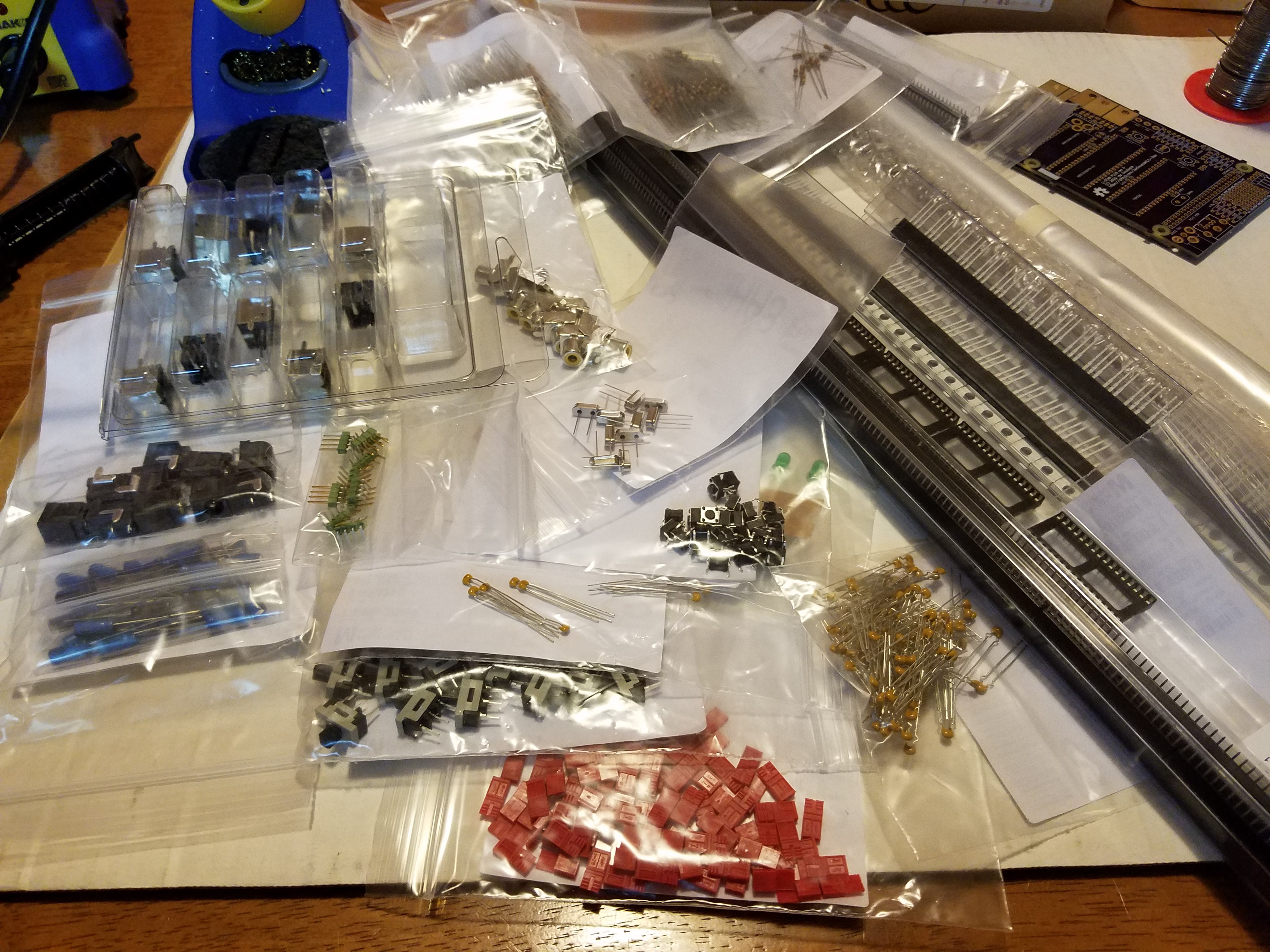
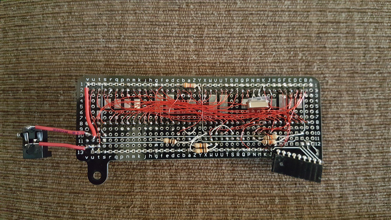
06/11/2018 at 20:02 • 2 comments![]() If you've followed me long enough, you know that my original purpose for the #Propeddle: Software-Defined 6502 Computer project was to build a replica of the Commodore PET-2001 and CBM series computers. The PET-2001 was the first computer I ever used, when I was about 11 years old in 1978. And now I've finally made a start on writing a software-defined computer project to emulate the PET/CBM on L-Star. As you can see in the picture, I have a long way to go.---------- more ----------
If you've followed me long enough, you know that my original purpose for the #Propeddle: Software-Defined 6502 Computer project was to build a replica of the Commodore PET-2001 and CBM series computers. The PET-2001 was the first computer I ever used, when I was about 11 years old in 1978. And now I've finally made a start on writing a software-defined computer project to emulate the PET/CBM on L-Star. As you can see in the picture, I have a long way to go.---------- more ----------The early PET/CBM machines had up to 32KB RAM on board, a character-based memory-mapped video display, 8KB ROM for Microsoft BASIC, 2K ROM for the screen-based editor, and 4KB for the operating system which Commodore called the "Kernal". There were 3 simple I/O chips in the early models: one for the keyboard and the cassette interface, one for the IEEE-488 (GPIB) interface, and one for the second cassette port and the user port. Later models added a CRT controller chip to simplify the video hardware.
RAM and ROM
In the projects that I've already written for L-Star, I've extensively used the Memory module which give the 6502 access to a memory area in the hub of the Propeller. To emulate a ROM, all I need to do in Spin is to put a "file" command in the source code to load a ROM image file and then run a Memory module to map it into 6502 address space. I can do this with RAM too, but the Propeller only has 32KB of hub memory available, part of which is used up by the program. Though it would be possible, in theory, to use hub RAM as 6502 RAM for the PET/CBM project, it's much easier to just use an external SRAM chip such as the one that's on the L-Star Plus board. One cog is in control of enabling the SRAM based on the address bus of the 6502, and because I already had that module, it was a matter of copying it and adding lines to initialize the module and start it up.
Video
In the original machines, video was the most complicated part of the hardware, because the RAM needs to be accessible by the 6502 while it's generating a constant signal. Just like in many other early 6502 computers, the entire system was built around the video hardware. Commodore figured out that with 40 characters per row, and a video line time of about 64 microseconds, it would be possible to run the CPU at about 1MHz and design some circuitry that alternates the access to the video hardware between the CPU and the video generator hardware twice per clock cycle. On the later 80-column motherboards, they used an even smarter approach where the video hardware sees the memory as 2048 words of 16 bits and decodes the characters at twice the speed.
With L-Star, the video part is easy because it basically has already been done. The Propeller is really good at generating video; it has I/O registers and assembly instructions to help with this. It can do 6-bit VGA or PAL or NTSC composite video, but all those modes need 3 or 4 or 8 pins. L-Star doesn't have that many pins available (most pins are connected to the 65C02) so I use the 1-pin TV driver which is fine for a monochrome text video output similar the PET/CBM. That software module wasn't written by me but by a couple of smart guys in the Parallax forums. I only had to convert the PETSCII font from a ROM dump at ftp.zimmers.net to the correct format for the 1-pin TV driver.
There are actually two fonts in a PET/CBM: one that has upper and lower case characters, and one that has upper case and graphics. And there are actually differences between the fonts in the PET and the fonts in the later CBM machines. But my short term goal was to get text on the screen, and fortunately that's just a few lines of code to start the video cog. And then another line of code to start another Memory module to give the 6502 access to the hub memory that represents the characters on the screen.
IEEE-488/GPIB
The PET/CBM talked to peripherals via a parallel interface using a standard called IEEE-488. That standard is more generally known as the Hewlett-Packard General Purpose Interface Bus (HP-GPIB or simply GPIB) and is still in use in instrumentation devices today. It made it possible for the Commodore engineers to design a computer and not worry about what kind of peripherals might one day be available for it. Commodore floppy drives (and printers and hard disks) are computers too (some floppy drives even have two CPU's), and they talk to the IEEE-488 bus via a standard protocol.
I probably won't implement emulation for the IEEE-488 bus. As far as I understand, real PET/CBMs work fine without the PIA chip that is used for the IEEE-488 interface, and there are probably better ways to load and save software and data into and out of memory. And if you want to connect L-Star to a real floppy drive, you'll have to build hardware anyway, so the need to add a PIA (and an address decoder) is probably not a big deal.
Keyboard and Cassette
PET/CBM's have two cassette interfaces, but most people only used one of them (professional users probably used a floppy drive and no tape at all). As mentioned before, there are probably better ways to get software and data in and out, so I don't think I'll write code to emulate the cassette, at least not for now. It would be nice to use the serial port (P30 and P31) on the Propeller, but I may run into trouble with that; I'll get back to this in a few minutes.
The keyboard that was used on the PET/CBM was a matrix keyboard on two ports of a PIA chip (a different one from the IEEE-488 interface). I wrote a driver for a matrix keyboard in the OSI Superboard emulator, and I'll probably modify that for the PET project. I may have to do a bit of a start-over because I'll have to use the 1-pin keyboard driver and the OSI keyboard uses 2 pins.
Tricky I/O
If you're somewhat familiar with other L-Star projects, you'll know that it has 3 uncommitted pins on the Propeller, which aren't connected to anything except the expansion header and the jumper bed. And if you counted along with the story above, you will have concluded that one pin is needed for video, one to control the SRAM chip and one to get input from a PS/2 keyboard. That means all pins are in use.
This is a problem, because there is one feature that I haven't mentioned yet: in the PET/CBM, the IRQ line is activated sixty or fifty times per second, depending on the mains frequency (I think the signal actually comes from the video circuitry but that doesn't matter). This is used to time operations in programs, let the cursor blink, etc. And there's no pin free on the Propeller to generate the signal that's supposed to go to the IRQ line of the 6502.
I'm not sure yet how to solve this. I could use P30 (which is normally used for serial transmit) to connect to !IRQ. That makes it difficult or impossible to use the serial port while the emulation is running, unless I write some software to implement a 1-pin serial port.
Another possibility is to not implement a keyboard emulator for the PS/2 keyboard, so it frees up a pin that can be used for !IRQ. But that makes it necessary to connect a computer to the serial port to generate keyboard input. Also not a very good solution; I'd like to the design to be stand-alone.
I could also try to do something in software: fifty or sixty times per second, I could let the Propeller feed a BRK instruction to the 6502 which is executed pretty much the same as an IRQ interrupt. But a normal IRQ doesn't set the B flag in the flags register whereas the BRK instruction does. So the Propeller will also have to interfere when the 6502 pushes the flags onto the stack, or when it accesses the location on the stack where they are stored. That could become very complicated. Which is somewhat ironic because in the real computer, the circuit that generates the interrupt is so very simple.
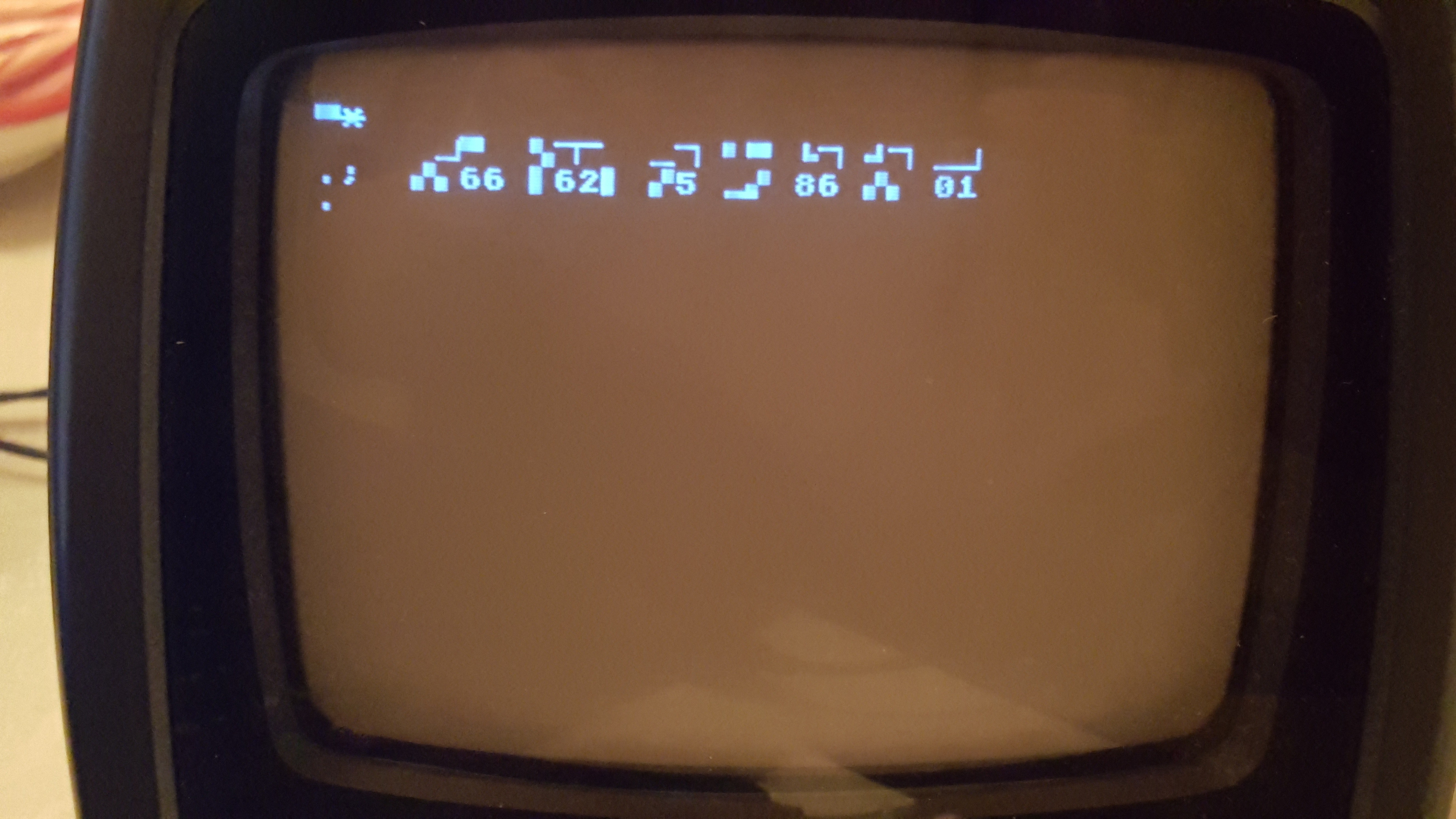
So About These First Life-Signs?
In the picture above, you see what appeared on the screen when I emulated just the RAM (with the SRAM module), the video, and the ROM. No peripheral chips are emulated yet. What I would expect on the screen is a message "COMMODORE BASIC" and "31743 BYTES FREE". But it looks like the execution drops into the machine language monitor as if it executed a BRK instruction. I suspect that the behavior is caused by a wrong combination of ROM image files. I started on the PET project about 2 years ago and hit a snag; I don't remember what it was but it wouldn't put anything on the screen at all. The project got shelved but now I picked it up and made some tweaks and write a module to trace the 6502 to follow what it's doing. I know I experimented with various combinations of ROMs when I worked on it before, so maybe what's in there is not correct, and somewhere somehow the code in one ROM jumps or calls code in another ROM that's not in the location where it's supposed to be.
What worries me more is that the display is garbled: That means that the 6502 is writing data to emulated screen memory but there are some bits that are mangled. I have a feeling the RAM chip is holding the databus a little bit too long at the end of a clock cycle, so I may have to tweak the Propeller code a little. The 6502 has to execute a lot of code and read and write a lot of locations in ROM and RAM to get to the point where it displays the Machine Language Monitor prompt, so I'm optimistic that it's fixable.
-
Back in Stock!
05/26/2017 at 06:38 • 3 comments![]()
Got parts, got PCB's, getting Prop Plugs in a day or two.
That means L-Star is back in stock!
Order here: https://www.tindie.com/products/jac_goudsmit/l-star-plus-software-defined-6502-computer/ (or click on the Tindie link on the project page).
-
Some Ideas for the Future...
01/12/2017 at 23:05 • 4 commentsI received the second batch of production boards and parts, so the kit is back in stock on Tindie. Meanwhile, I figured I should write down what the plans are, especially for the l-star.org website. See "after the break" for some ideas I'm working on.
First of all, I've been working some tutorials for owners (or those who want to follow along at home) to learn how to "write their own computer" using the C language:![]()
- The first tutorial/demo proposes a basic framework that defines types and macros to get started, and generates a clock signal "as fast as possible" and lets you observe how the 65C02 reset sequence works
- The second tutorial/demo shows how to run a separate cog that presents part of the Propeller's hub memory to the 65C02
- The third tutorial/demo shows how the PIA of the Apple 1 can be emulated in C, and loads the ROM from Vince Briel's Replica 1 to make the L-Star into an Apple 1 emulator.
The code for the above is already on Github here, but I'm still working on the text that will be posted on the website soon.
Future Tutorials
I'm thinking the next tutorials should be:
- How to convert time-critical code into inline assembler, and how to use a Propeller timer as clock generator.
- How to use the SRAM chip.
- How to implement emulation of memory-mapped (text) video, and how to emulate a matrix keyboard, culminating into an emulator of the Ohio Scientific Challenger C1P (also known as the Superboard II or UK-101).
- How to implement a virtual storage device using the EEPROM.
- How to make up your own system, maybe running Forth.
Future Hardware
I have several ideas I want to work on in the hardware area:
- Commodore PET emulator: this is what I originally intended the project to do, but it would need a way to generate interrupts at 60Hz or 50Hz and I'm trying to think of a way to do that without adding extra hardware.
- Acorn Atom (a.k.a. Hob-bit computer) emulator; this should also be possible without extra hardware.
- An expansion board with 24 (or more) tactile switches and six or eight 7-segment displays to emulate a Kim-1 or Elektor Junior
- A "Pro" version for advanced experiments: this would probably be a version of the board that doesn't have the I/O and jumpers on board; it would have a right-angle connector for expansion, which would plug into a new passive motherboard (or simply an IDC connector on a ribbon cable) to connect to multiple expansion boards. Or, going slightly further, something resembling RC2014 but perhaps using card edge connectors.
- A "Pro 16" version that uses a 65C816 instead of a 65C02 and has (say) 4MB of static RAM and runs faster while the CPU is not accessing the Propeller. This could perhaps be used to emulate the Mensch Computer or simply to run Fuzix. You know, just for giggles.
- A modification to use a PIC microcontroller instead of a Prop Plug to connect it to a host system. This would eliminate the FTDI controller, the one and only chip in the design that's not available in a DIP package, and would make it easier to put the system into an enclosure.
Are You Still Reading?
I have disappointingly little time to get all this stuff done, and I hope owners and enthusiasts will step up to help some day. Whether you have a kit or not, if you've read through the documentation and you can think of something you want (me) to do with the L-Star, or if you would like to propose any ideas for expansion boards or software projects, let me know!
-
Now For Sale on Tindie!
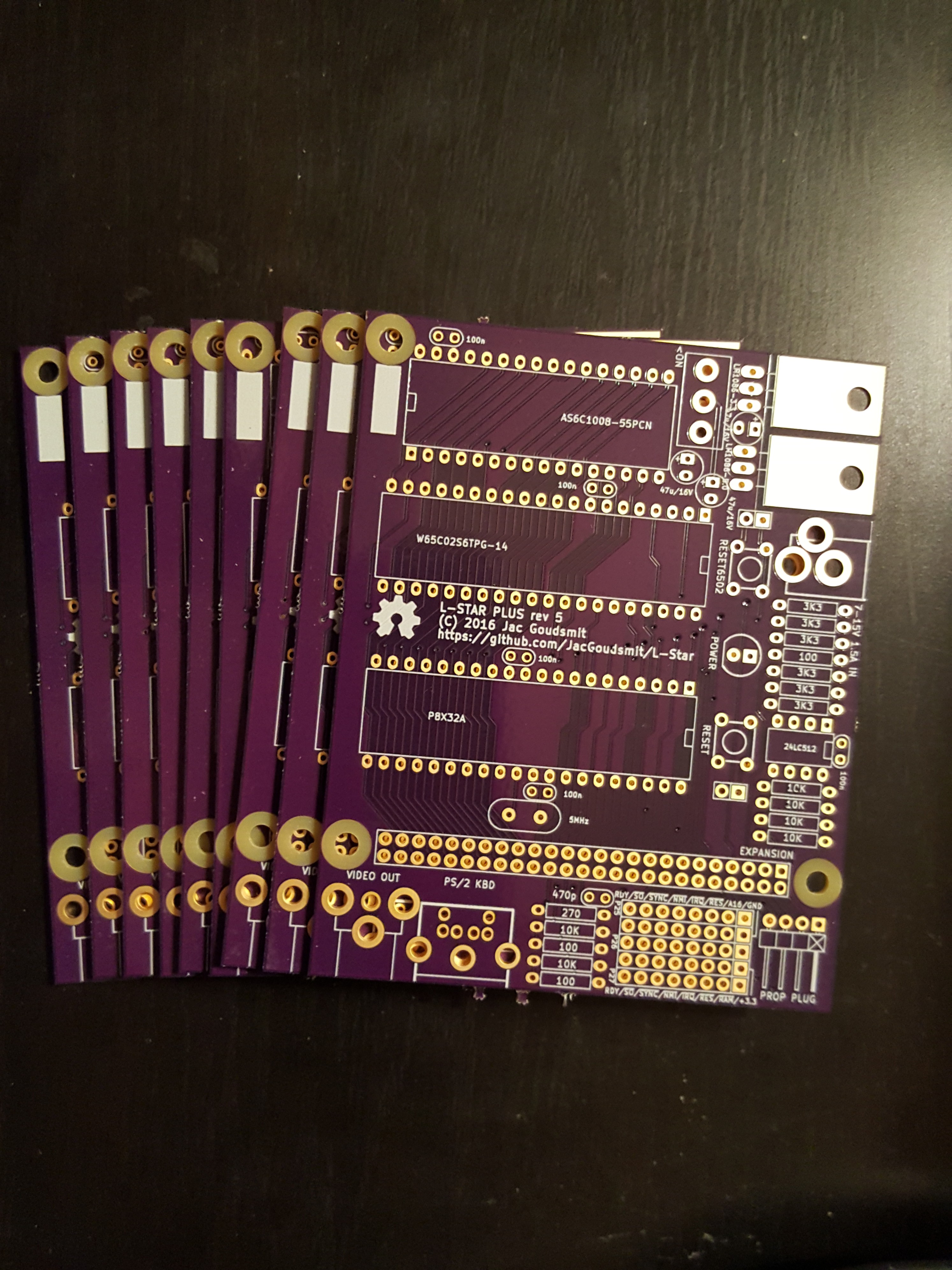
11/08/2016 at 05:34 • 0 commentsI received the PCB's for the first production run!
![]()
That means you can now actually buy the project as a kit on Tindie. Click the link on the project page to order.
I'll be setting up the web site at l-star.org this week (hopefully), so that new owners will have a place to go to find build instructions, documentation, and maybe even a forum to share what they've done with the system, ask questions, or make suggestions. If it's going to be a lot of work, it means I'm doing it right!
===Jac
-
Hardware Revision 5: Could This Be the One?
10/11/2016 at 04:15 • 0 commentsAfter the disaster with Rev. 4 (see the last log), I learned a couple of things and made some changes resulting in Rev. 5:
![]()
The mounting hole in the lower left corner of the PCB has been a pain since the start of the project, and if you look at the project logs, you can see it has moved around a lot. For Rev. 5 it's finally where it belongs: in the corner. I swapped the locations of the on/off switch and the power socket, so I could move the SRAM chip up a little, to make space for the hole. I can't believe I didn't think about it earlier and I don't think I'll have to move it again. That means it will be the location of the mounting hole on future expansion boards too.
That sounds pretty final, and it is. I think Rev. 5 is the design that will go into production. I adjusted some parameters (such as the pad-to-soldermask clearance, the flood plane clearance and minimum width, and the via drill and pad size), to prevent problems from Rev. 4 from reoccurring. I also nudged the keyboard connector over a little bit, to make it easier to prevent short circuits with the resistors when soldering.
Nevertheless, after the problems of Rev 4, I didn't feel confident enough to order a full production run of Rev. 5 at OSHPark. I placed a regular 3-board order and if they turn out okay, I'll order more.
I also ordered enough parts to have a small number of kits available on Tindie as soon as possible. But it looks like I may have to order a bigger batch of parts soon: There are already enough people on the waiting list to sell most kits of the first batch...
I updated the links to the OSHPark and Mouser order pages in case you want to order your own, but of course that will be more expensive than ordering from my Tindie page once it's ready. Thanks for your patience!
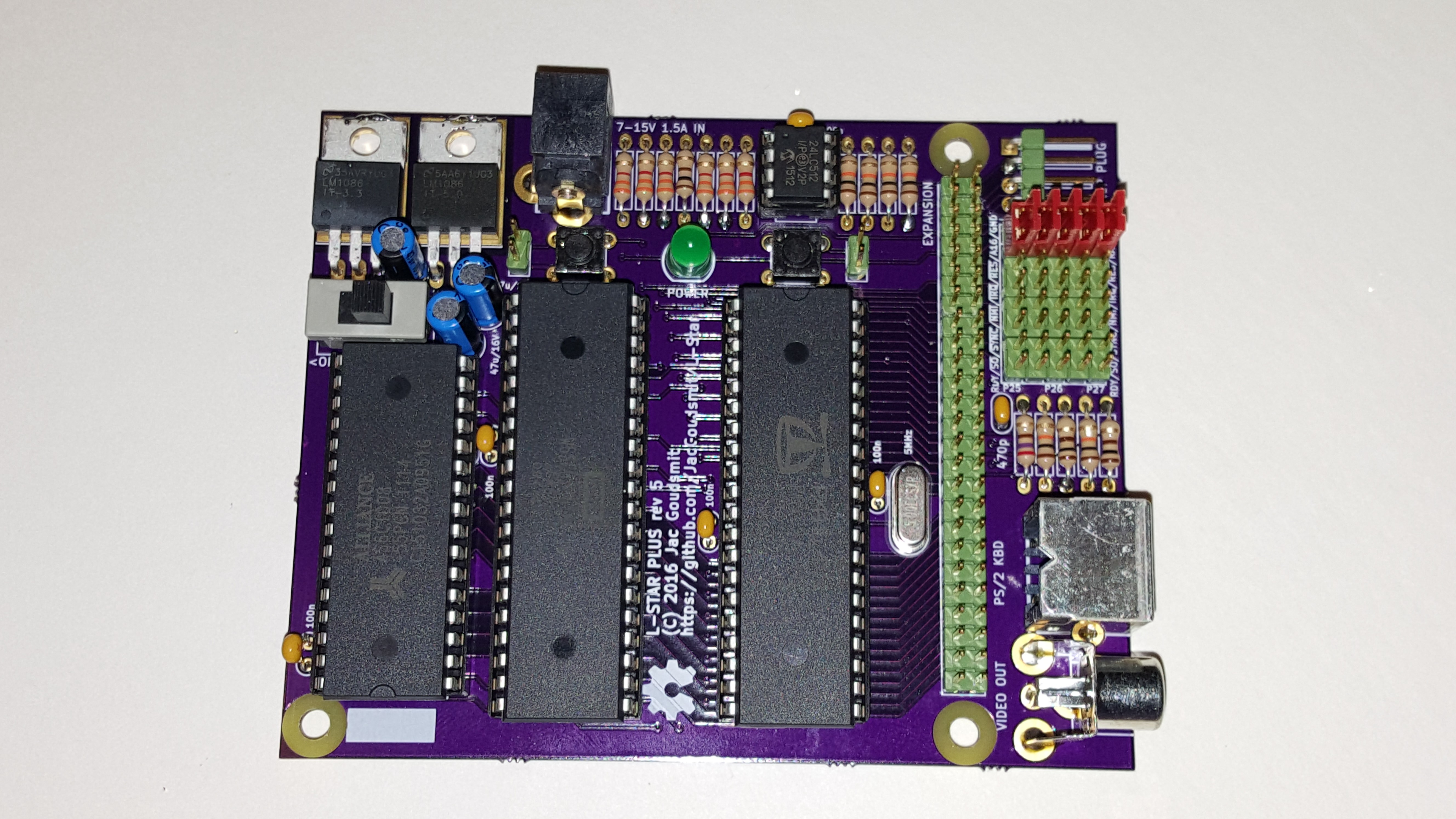
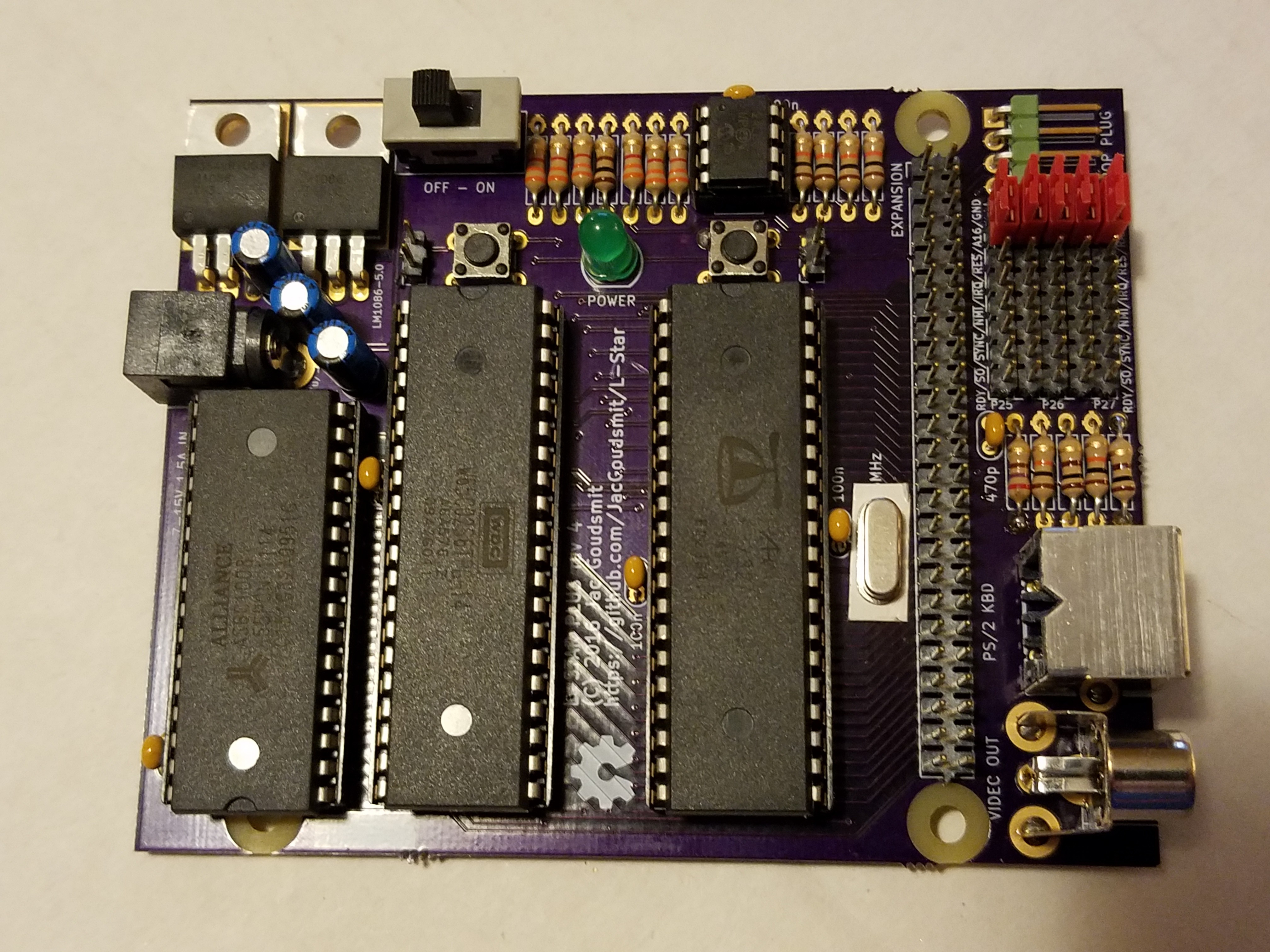
UPDATE: I got the Rev. 5 boards back from OSHPark and built one; see the updated picture at the top of the article. As you can see, the green headers are back!
-
So Much Fail: Building the Rev. 4 Boards.
09/13/2016 at 07:09 • 1 commentLast Friday, the Rev. 4 boards arrived from OSHPark, and a Purple PCB Day is always a good day. Also, BBC America was doing their Star Trek 50th Anniversary Marathon of all the Original Series episodes and I was the only one home, so this was going to be a fun night of watching the young version of Khan, Zefram Cochrane and the Tribbles, and soldering my project together. Or not?
![Two of these are not like the others...]()
Just Kitting
The first thing I did was to sort through the big box of parts that I had gotten from Mouser earlier in the week, with enough passive parts for 10 kits and then some. I decided not to get all the chips because I still have most of the chips from the first production run of #Propeddle: Software-Defined 6502 Computer and I could easily reuse those chips even though they're a few years old. They've been on conductive foam all that time so they should be fine. I figured it might be a better idea to invest a little bit into some extra passive parts so that I could get them at a lower price. For example, resistors get a lot cheaper per part, if you buy 200 of them instead of, say, 10 or 60.
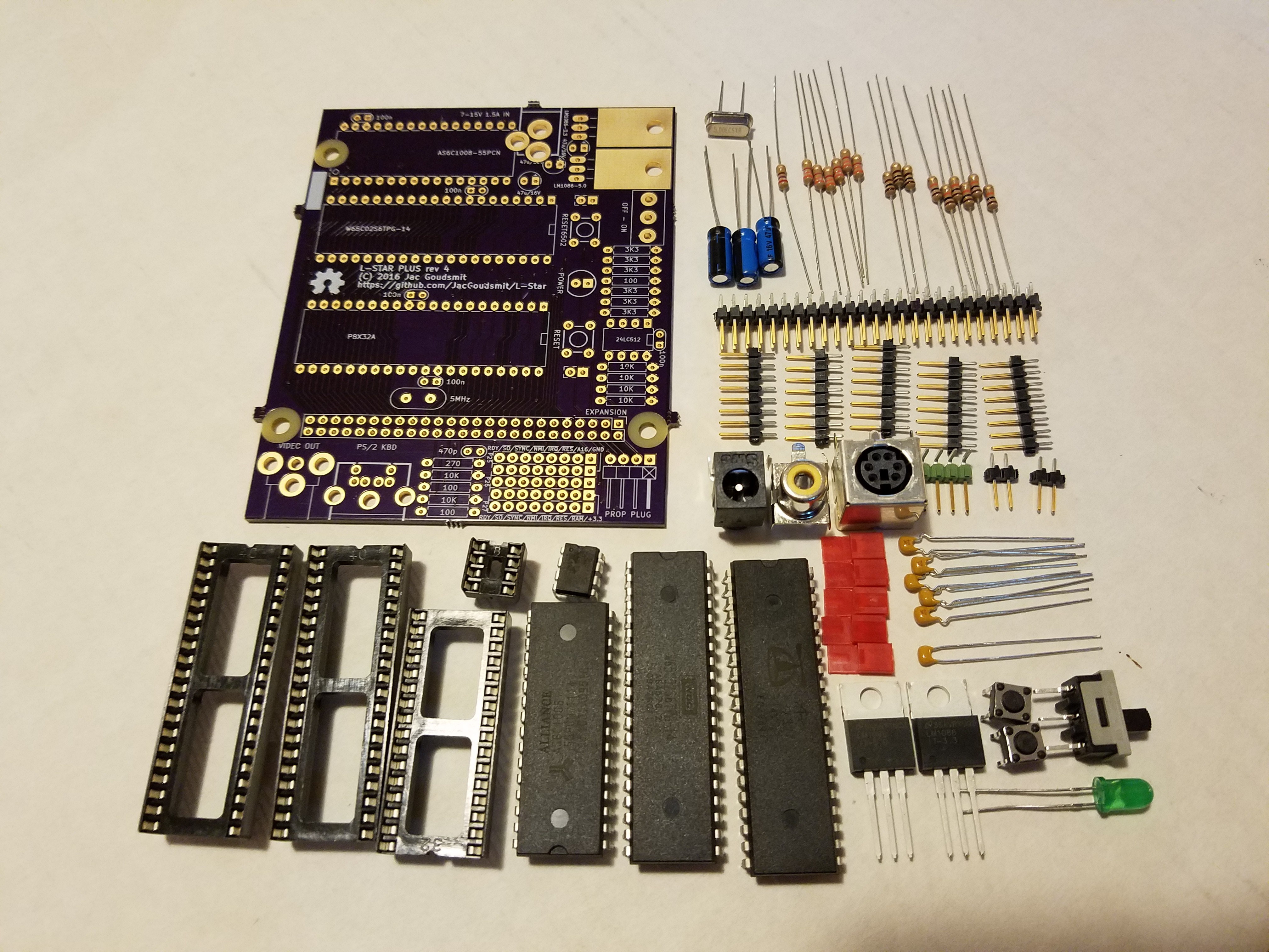
![The (mostly passive) parts for 10 L-Star kits, and then some.]()
![And this is what will come in one kit, including the ICs that I "prepared" earlier.]()
Board 400
I've soldered so many different versions of my own project that I can almost do it in my sleep now. Well... That's an exaggeration of course, but the actual assembly of the first board which I will call Board 400, went pretty fast. I found a couple of minor problems that I'll fix for the production version (for example, now that the board is so much smaller as when I started, some parts are really too close together so I'm going to have to move some things around to make it easy to solder for beginners). But nothing was obviously wrong. I went through the entire assembly in one go and took pictures along the way that I might use for the building instructions, but I didn't really test anything along the way. You can probably guess where this story is going, right?
![Whether the power is on or not, the LED on this board is not going to light up.]()
The board looks beautiful, and though things get crowded in a few places (which I will fix for the production version, as I said), it was easy to solder. But when I plugged it in... nothing happened.
As it turned out, there was a short between 3.3V and GND (the flood planes on the top and bottom side). This was the first time that that ever happened with any board from @oshpark. I've always gotten excellent quality PCB's from them and this was no exception. There was no short on the unpopulated boards. So what went wrong?
I started desoldering some of the parts from the first board (particularly, the ones that I noticed were close to other parts) to see if I had been too sloppy with my soldering. But the short didn't go away. Bummer! I went to bed and figured I'd look at it again on Saturday morning.
I had a closer look on Saturday but I didn't get any wiser from it. My 20 year old solder tin that I brought with me from Europe when I emigrated, sprayed rosin core everywhere of course, so I cleaned it up a bit to see if I could see any tin where there shouldn't be any. I didn't.
Board 401
So I sort of gave up on "board 400" and decided to solder together "board 401". I started with the resistors, and the MLCC capacitors. Then just for giggles I put my multimeter on the board. This one was shorted out too! What the actual beep?
![This is how far I got with the 401 board, at first: just the resistors and it shorted out.]()
I desoldered the capacitors from board 401 because it was easy to do, and measured again. Still shorted. I used solder wick and a solder sucker to clean the pads. Still shorted.
Board 402
I gave up on board 401 and started putting together board 402. I didn't really want to put all those boards together; as much fun as it is to solder them together, I really don't need that many L-Stars laying around my house! And if I was going to put all my own kits together for myself, I wasn't going to get paid for the parts. The passive components alone are probably close to $25 per board, and that's after I switched to the cheap header-by-the-mile parts instead of the cool green headers that I had before (which I will probably switch back to).
![Board 402 looks the same as the 400. Except it works.]()
I started board 402 with the LED and the power supply, so I could quickly plug it in after soldering each part. But I didn't run into any problems at all, this one was just perfect and super easy.
Back to Board 401
Meanwhile, I had posted my non-progress on Google+ and got an email from Laen at OSHPark. He said he noticed the clearance around the solder mask was a little on the high side.
![Board #401 before the cleanup. There's your problem! And no, it's not those blobs of solder in the middle.]()
A close-up photo of board 401 reveals what the problem really was. When you look at the board with normal, say 49 year old eyes, you might think those shiny things at the edges of the solder islands are just like the the light reflecting off the edge of the solder resist near the edge of the board, but they are exposed copper from the GND flood plane. I must have played with the settings at one point and set the pad-to-solder-resist to 0.2mm (almost 0.008 inches) instead of 2 mils (0.002 inches). I bet I shorted out almost all those resistors I soldered in. To paraphrase captain Kirk: Face, the palmed front here.
I decided maybe board 401 would be salvageable, now I knew what the problem was. I cleaned up all the islands (which took hours!) and finally cleared the short circuit. Then I did the same as with board 402: I mounted the LED and power supply first, and then added each component with a quick light-up test in between. I caused (and fixed) a few more shorts but when I was done, I decided this would do as a demo model or something. I would have to put a sticker on the back side to remind me never to do any soldering on it, lest it would short out again. And that's when Murphy struck again.
Murphy's last laugh
I soon found out that, though I had avoided shorting out the flood planes (or anything else), there were a few points on the board that weren't connected even though they should be. For example, I could communicate with the Propeller but I couldn't store the program into the EEPROM. Strange. I tried another EEPROM that worked fine on board 402... Bupkis.
So I pulled out the beeping multimeter again and found out one of the I2C wires wasn't connected. I put on a botch wire to fix it, thinking nothing of it. No big deal, "Chips happen" as they say. But then I needed another one, and another, and another. The entire data bus except for one bit was disconnected between the Propeller and the 65C02. Can you see why, in the next picture?
![It's not the soldering (though that looks pretty crappy at this magnification). Look closely!]()
No, it's not because of my (I admit, utterly shoddy) soldering; it's because most of those vias don't have a hole in them, so they're not vias at all, they're just islands. The tiny drill that the board house used to drill vias, must have broken in the middle of my board, and nobody noticed it.
Conclusion
So yeah. About $60 in parts lost, as well as two OSHPark PCB's and pretty much a whole weekend. Lessons learned:
- Figure out exactly what the best settings are for clearance (pad-to-pad and pad-to-solder-resist)
- Don't use the most extreme settings that your PCB provider offers, unless you have to (I bet 0.015 inch drills break a lot).
- Solder accurately even if you've done the same thing 20 times already
And uh... suggestions on better solder tin are welcome, solder tin donations even more :-)
===Jac
-
Hardware Revision 4: Now with All the Pins You Need!
08/28/2016 at 22:08 • 0 commentsThis weekend I was able to do some work on the hardware of the project again, and I decided to bump the version number, so it is with pride and joy that I announce Revision 4 of the L-Star hardware.
![]()
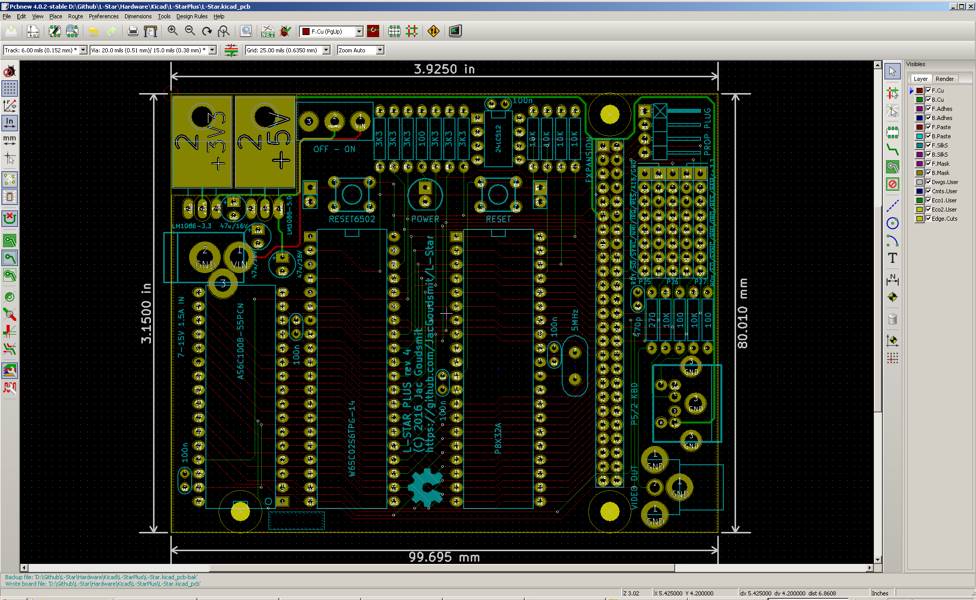
One change that I made since Rev. 3 (which I never built) is that the PCB is now even smaller. It's now within a hair of fitting within the "magical" 80x100mm "Half Eurocard" size. The short side is 0.01mm too wide to fit into the crazy limit imposed by the free and cheap versions of Eagle. I don't think I'll fix that unless someone asks; I think this design is going to be the production version.
The most important improvement compared to revision 3 is that the expansion port is now a 50-pin header instead of a 40-pin header. As I mentioned in the previous project log, the location of the expansion port was always designed with the possibility that there could be a 50 pin header some day, and that day is now. For most projects, the original 40 pins may be enough, but the extra pins should remove any fears of future regrets: Simply every single important control signal is on the connector. The added pins are:
- RDY: The RDY pin can be used to hold execution (insert wait states) on the 6502: when it is pulled LOW, the 6502 stops executing, but the address bus and data bus are still going through their usual motions. In the original 6502 it only stopped read cycles and not write cycles, and it was intended to deal with slow hardware, usually ROMs. On the WDC 65C02 in this project, the RDY pin also stops when the processor is doing a write cycle. So on old hardware, the pin was rarely used and because of the change in the WDC processor, any use that can't be emulated by letting the Propeller stop the clock is probably not worth fixing, so I left it off the expansion port until now. In the unlikely case that it might be useful for a project where an expansion board controls the pin, it's available now.
- BE: The Bus Enable pin is a unique feature of the WDC 65C02. It puts the address bus, data bus and R/~W pin in a disconnected state to make it possible for other devices to use the bus. I admit, it was tempting to use it to let the Propeller access the SRAM chip directly, but because I was out of pins on the Propeller, and because it's easy to work around that problem with software (i.e. simply let the Propeller feed dummy instructions to the 6502 that take care of filling the RAM) I decided not to use it. I still expect that it will be difficult to use, because the Propeller has to know when to stop paying attention to the bus, too. But anyway, it's on the expansion port now.
- A16 and ~RAMEN: In most cases, it would be enough to let the Propeller have control over the SRAM chip (if it's even necessary to have an SRAM chip in the first place). But now the expansion port has the RAM control signals, it's possible to put some sort of hardware address decoding on there and keep Propeller pins free for other purposes
- KBCLK, KBDATA and TVOUT: It makes sense to have these on an expansion board: for one thing, it will make it possible to do things like generate color video from the expansion board. And by putting all signals in the jumper block on the expansion port, it's possible to replicate the jumper block on the expansion board, or even to remove the right side of the board (Prop plug, jumper block PS/2 and video connectors) completely, and/or put them on a separate board that's connected to L-Star via a ribbon cable.
- ~RES: This is the reset input for the Propeller, and though there already is a header to connect this signal to a switch in an enclosure, it's also a good idea to have it on the expansion port. For example: if you would want to separate the "right side" of the board from the rest of the board, the reset line is needed because it's also on the Prop Plug.
- Two GND pins: When there are so many pins connected to a second board in the system, it's always a good idea to have a good ground reference.
There are actual people owning actual hardware that uses the 40 pin connector, so the 50-pin connector is backwards compatible with the 40-pin connector. The two GND pins were added on one side and the 8 other pins were added on the other side. I don't expect to make any further changes to the pinout, because all the signals that I think could possibly interesting to any expansion devices, are on the connector. The only ones that are not on there are the Propeller clock and the brown-out protection. But I already decided that it's not worth making any changes to those: the project is intended for those who want to learn about the 6502, and while those two would useful, they would also be a distraction from the intentions of the project and add expense.
I ordered a batch of PCB's from OSHPark, and I plan to build it to make sure it works, I'm thinking of leaving the chips off the Mouser order, and stocking up on the passive components so I can do a production run soon, and finally put the project up on Tindie.
-
Hardware Revision 3
06/15/2016 at 03:27 • 2 commentsAs I mentioned in the "Hardware Revision 2" posting, there were some small but significant problems with that version of the schematic and PCB:
- The ~RAMEN pin ended up in the wrong place on the jumper block, which would make it difficult to use video, a keyboard and the on-board SRAM chip at the same time.
- With the added on/off switch, the board got a little crowded around the RESET6502 button which made it harder to press the button. Also I didn't like that the buttons didn't line up nicely in the layout anymore.
- The board still had the old problem that the solder islands for most parts/footprints were a bit on the small side.
Here's a picture of the Revision 3 layout:
![]()
First of all, I switched the location of A16 and ~RAMEN (and the accompanying 3.3V and GND pins) so that ~RAMEN can be jumpered to P27 which is connected to KBCLK in the "default" configuration. I considered moving things around so that ~RAMEN would be the default for P27 and KBCLK would be an alternative, but I decided it would cause too much confusion so I didn't do that.
I moved the power LED to a location between the pushbutton switches, so now there should be enough space for a finger to push the button again. I also lined the pushbuttons up, close to the places where they were in revision 1. The LED is in a sort-of-odd place, so far away from the power connector and the power switch, but it's where there was enough space for the traces. I would have liked it on the right side of the board (and the power switch too) because I imagine that side will be pointing towards the user, but that's simply impossible unless I make the board a lot bigger.
I edited all the footprints on the board and made sure that they all use solder islands with a size that's big enough to solder if you have a non-professional solder iron, or if (like me) you have some old solder tin that doesn't flow as well as it used to do.
I discovered another oversight that I wanted to fix: the jumpers didn't have the ~RESET6502 signal on them. So I changed the jumper block from 7-by-5 to 8-by-5 and added the signal near the top, where it was easy to line up with the ~RES6502 pin on the expansion port connector. As it turns out, this had a fortunate side-effect: I found out that five 10-pin pin headers are cheaper than two 20-pin headers of the same series (the ones with the green plastic that I got by mistake but look really good and nicely define the color scheme of the project, along with the purple PCB and the red jumpers). This will make it easier to break/cut the jumpers to size for the final kit.
I also made the footprint of the voltage regulators a little smaller, which allowed me to reduce the board size again, and to line up the power switch with the RESET6502 pushbutton.
I haven't ordered parts or PCB's yet, because I'm considering another change: I'm thinking of putting the voltage regulators upright, and wiring them up differently so they'll be in parallel instead of in series. This will allow expansion boards to use more power on the 5V rail (the 3.3V regulator is currently fed by the 5V rail) and might reduce heat production because the current only has to go through one regulator instead of two. On the other hand, it might cause other problems like interference and the need for bigger electrolytic capacitors.
Another change I'm considering is to use a 50-pin expansion header instead of a 40-pin one. You may have noticed that there is just enough space to do that, and that's not a coincidence. A 50-pin header would make it possible to run the video and keyboard connectors to the expansion board, as well as some signals (~BE, A16, ~RAMEN) that I had to leave out because of the 40-pin limit. This would make it possible to design an expansion board that e.g. generates color video and uses the PS/2 keyboard, without the need to add connectors for them to the expansion board. And it would be possible to let an expansion board take over some functions take over some functions that currently only the Propeller on the L-Star board can do, such as controlling the SRAM chip. Furthermore, it lets me add some more pins to supply power to the expansion board, which is also a little bit of a concern.
L-Star: Software-Defined 6502 Computer
Replicate an Apple-1. Or an OSI Challenger. Or something else. Design your own 6502 computer by programming it.


 If you've followed me long enough, you know that my original purpose for the