jaromir.sukuba
-
3D printed case, part two
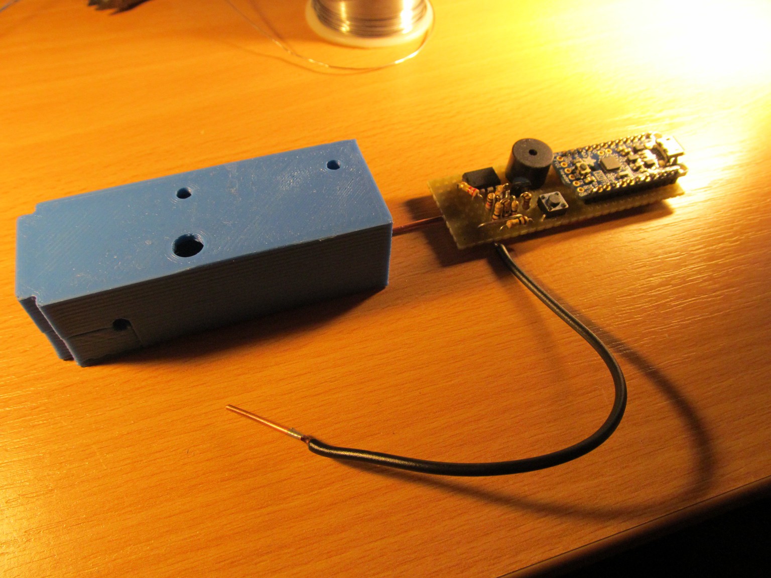
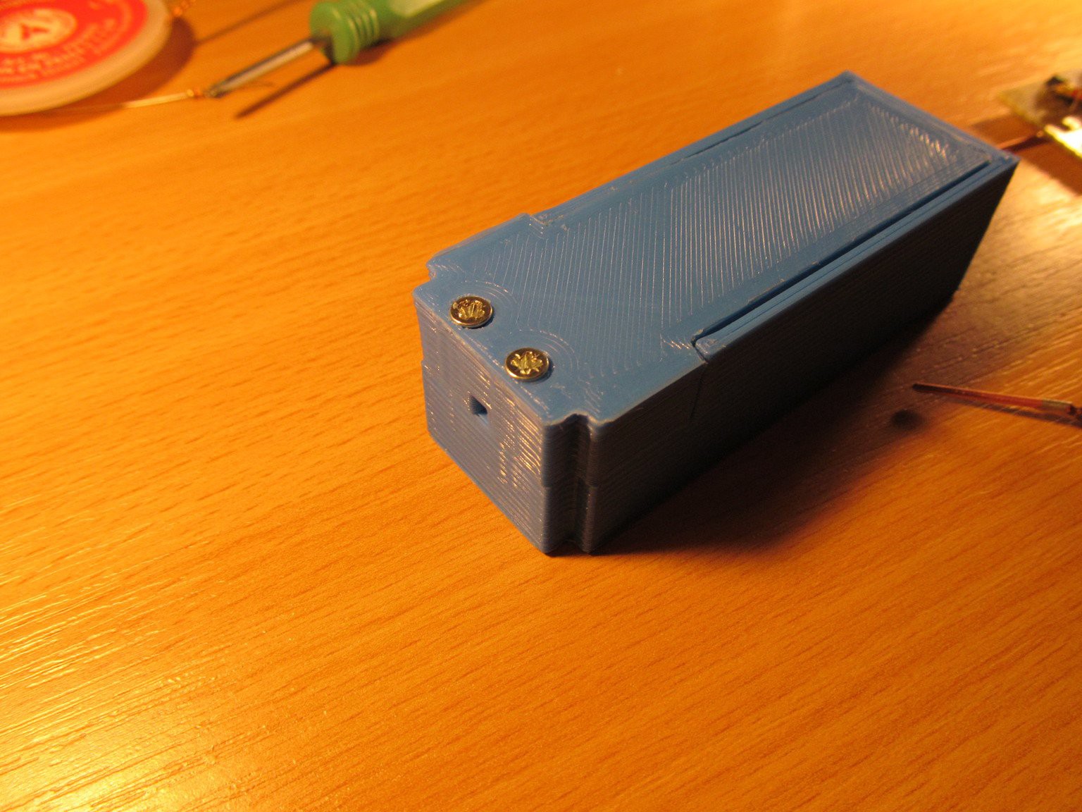
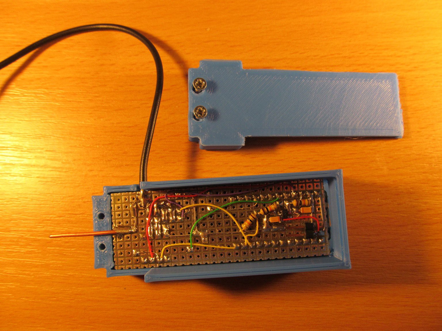
01/03/2015 at 02:57 • 0 commentsToday I printed case for shorty
![]()
![]()
![]()
![]()
and made a little demonstration of its functionality
-
3D printed case
12/29/2014 at 20:12 • 0 commentsHonestly, this week I spent a lot of time on another projects, like pavapro, but this is getting to its finish too.
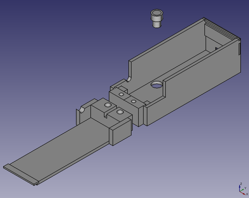
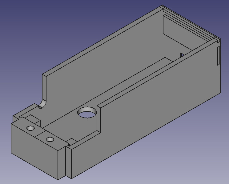
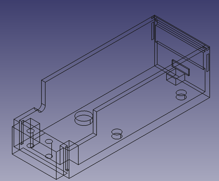
I designed a case for shorty in FreeCad...
![]()
![]()
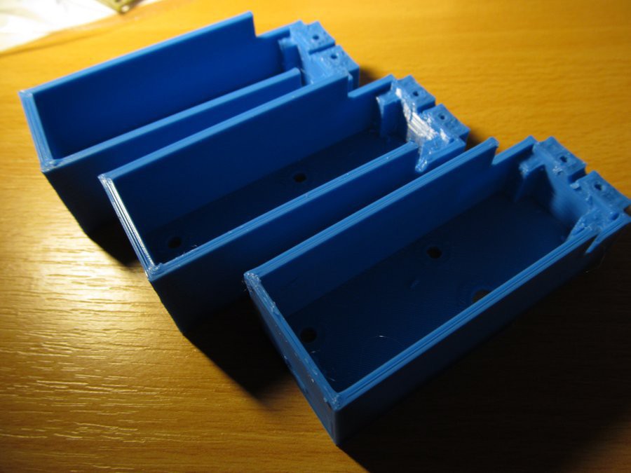
...and printed a few revisions of the case to found mistakes on each of them...
![]()
and yet none of them is OK, though I'm getting closer and closer. I should get beter in 3D design.
Regarding the software, I modified it to use the PNP transistor to switch off the resistor divider, so the current consumption can be lowered after a period of inactivity.
-
Things are getting real
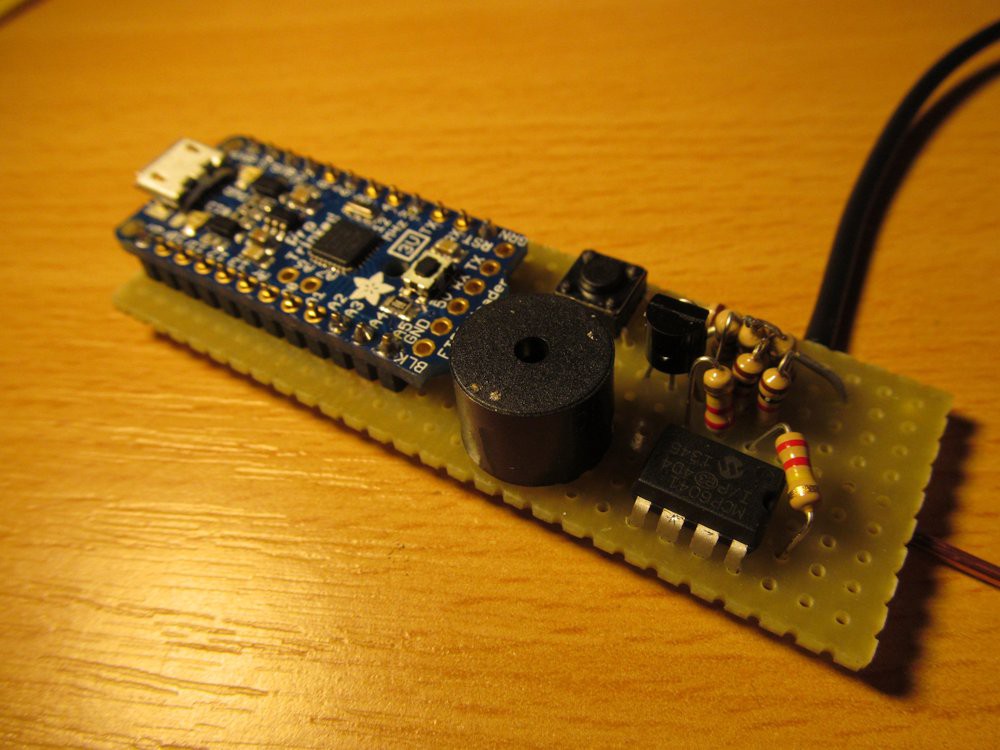
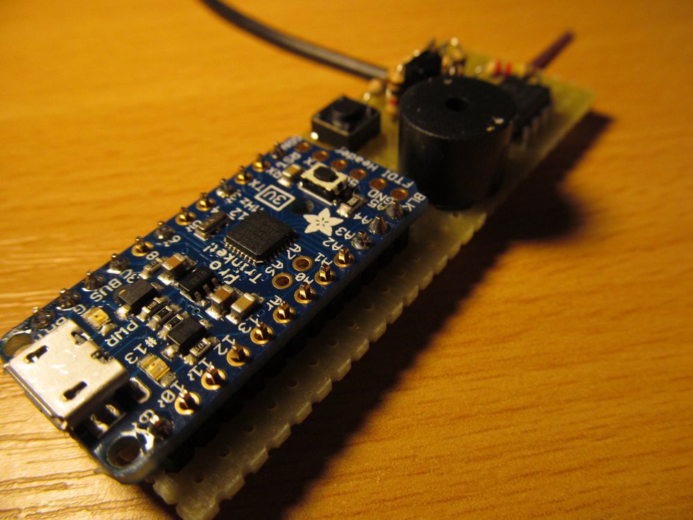
12/23/2014 at 22:13 • 0 commentsToday I put together the prototype. I used the same analog concept as discussed before. And this is how it looks:
![]()
I opted to use only two probes, opposed to full 4-wire connection. From first tests it looks good enough - I'm able to discriminate as much as few as milimeters of copper 0,3mm (12mil) wide track on PCB.
![]()
![]()
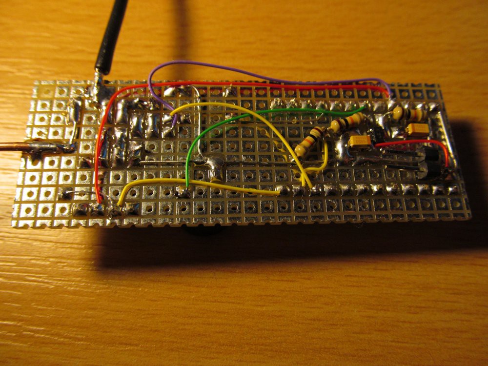
Closer look
And here is bottom side of the board:
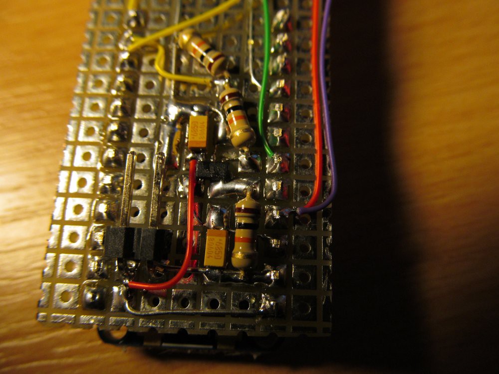
![]()
With detail of MCP73831 in SOIC package
![]()
Well, who doesn't feel to do this, can use adafruit LiIon backpak instead.
I wrote first quick and dirty firmware for it and it looks quite usable. After some cleanup, I'll set up github repository for it. But before it, I'm going to heat up 3D printer and design some package for this gadget.
-
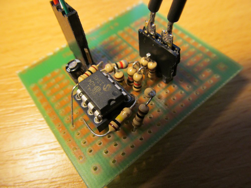
Input amplifier
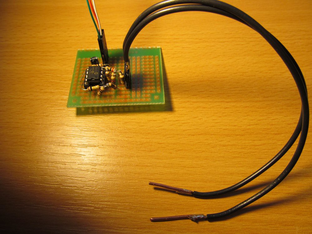
12/21/2014 at 10:38 • 0 commentsI protoboarded differential amplifier with opamp MCP6041 (I really love this opamp for low-power applications), with gain 100, resistors R1 = 82Ohm, R2 = 2Ohm, R3 = 2Ohm (see my previous project log) and put ordinary DMM on its output.
![]()
When input of amplifier was shorted, I got expected reading a few milivolts - input offset voltage multiplied by circuit gain - with open output I got full output voltage, slightly under 4V supply. So far so good.
Though the input has 4-wire connection to eliminate resistance of connactors and probes, I tried to make it simpler and used only two-wire probe, connected by 4-wire connection - eliminatiing the connector resistance, not probes.
![]()
I also prepared simple probes with copper ends.
Though not optimal setup, it works surprisingly good. When sliding the probes through copper track of PCB, the output voltage changed nicely with length and width of copper track - while DMM itself, switched to resistance measurement, showed just some random value around 1Ohm on the same tacks.
So far so good. I'm going to attach trinket pro and buzzer.
-
First thoughts
12/16/2014 at 14:28 • 0 commentsFor detecting where short circuits actually is, you can theoretically use DMM, but most of the DMMs have problems with resistances below 1Ohm (mostly limited by simple two-wire probes) and do have only optical indication of the value (=you must jump your eyes between PCB and DMM), so it is not that great tool for exact localization of the short circuit.
Having tool to distinguish between resistances in order of tens miliohms could enable me to find where the short circuit is. The tool doesn't have to have ability to display the exact value, only indication if the resistance goes down/up as I move electrodes closer to/further from the short circuit location. Sound indicator (buzzer) would be great for this, as I can fully concentrate my eyes on PCB, while beeping (low tone=low resistance; high tone=high resistance) would indicate the resistance.
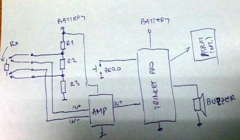
My first idea is something like this: three resistors (R1 mostly adjusts the measurement current, R2 limits the voltage on measured resistance; R3 produces slight voltage offset to allow differential amplifier to work correctly), differential amp itself (four resistors and opamp), trinket pro, buzzer, pushbutton (to allow "zero-ing" the "measurement") and optionally display.
![]()
By the way, I feel like four wire method will not be actaully needed, especially when probes will not be detachable, but I have to make some experiments with this.
Shorty - short circuit finder
Short circuit finder, especailly for PCB checking