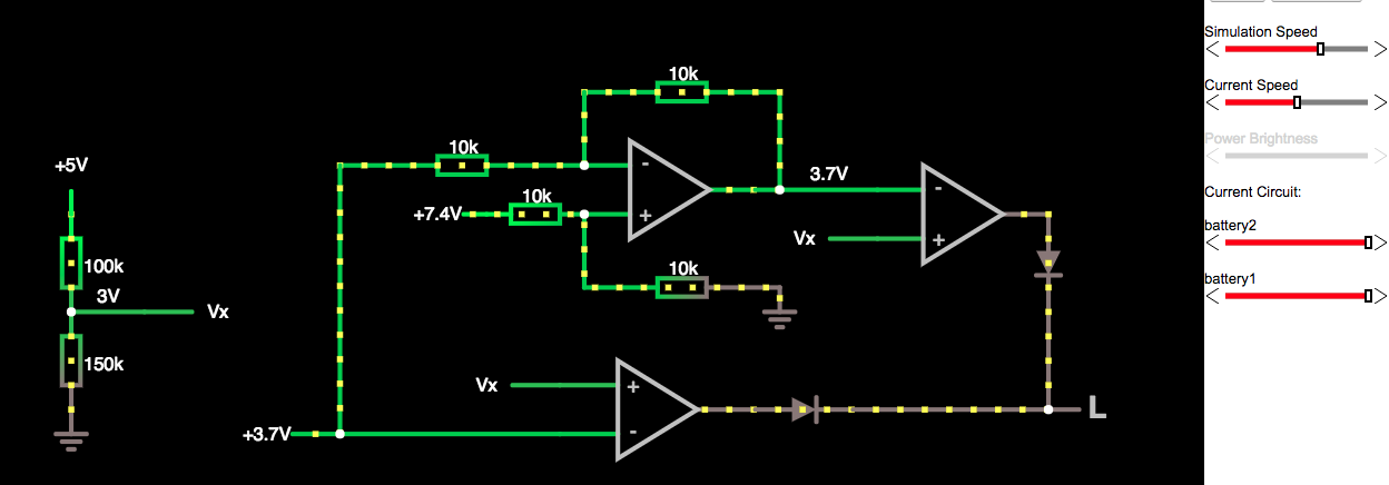
First of all, i want to translate my schematic - by hands - to the Circuit Simulator.

Link: https://goo.gl/LuN2R9
Component & parts:
- On the left we have a voltage divider, it produce the 3V output for the comparator.
- The triangles are the Op Amp:
- On the bottom and in the right up corner we has 2 Op Amp in comparator configuration.
- In the center, we have an Ap Amp in differential configuration.
- The 2 diodes in output at the comparators are there to avoid discharge current.
When one of the two battery fall below the Vx voltage - here 3V - the comparator output, connected to that battery, rise up.
If we connect the outputs of the diodes together at one of the Arduino's pin, we can advise the micro controller to jump in the deep sleep mode ( power off ) before damaging the batteries.
 Dave
Dave
Discussions
Become a Hackaday.io Member
Create an account to leave a comment. Already have an account? Log In.