ipaq3115
-
Teensy 3.6!
09/03/2016 at 19:13 • 5 comments![]()
Just saw Paul has a kickstarter out for his newest addition to the Teensy family. It looks awesome! Only a couple days left to get one https://www.kickstarter.com/projects/paulstoffregen/teensy-35-and-36. A real SDIO port for the sdcard and 4 times the RAM would make for a much speedier watch. Could possibly even handle one of the new 360x360 screens the latest and greatest smartwatches have been using... lots of possibilities.
-
Graphing battery voltage
01/12/2015 at 21:01 • 0 comments![]()
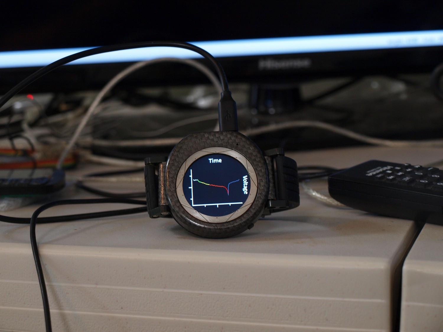
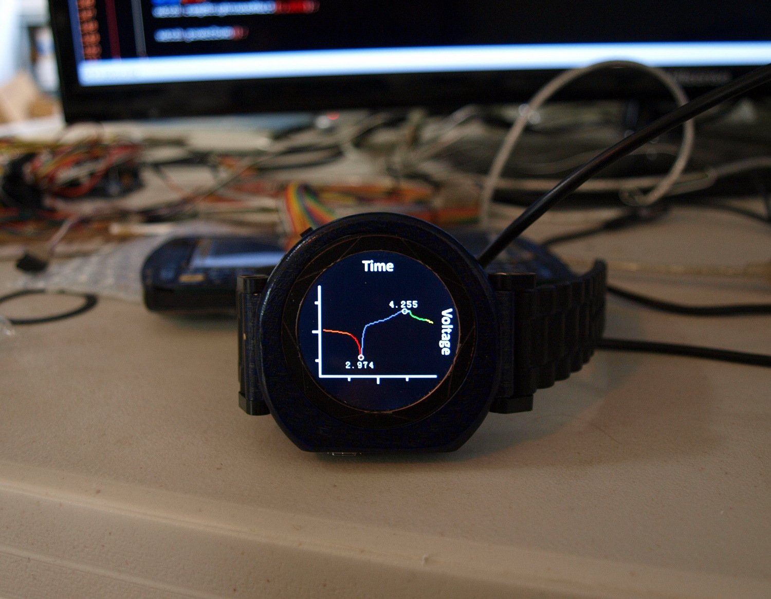
Did a full run down of the battery with the watch recording voltage. This is super easy to do because the BC127 does all of the battery management. Most of this just involved writing the library routines to poll the bluetooth and I just now got the recording to a file and graphing part working good. Next up is battery stats and building a lookup table to turn the voltage curve into a more linear 0 - 100% capacity kind of number.
EDIT: Put in some min/max voltage numbers and you can see the whole charge cycle.
![]()
-
LEDs!
01/03/2015 at 21:33 • 0 commentsAddressable leds are a lot cooler when you can control them from your wrist! Controlling things with a combination of the touch ring and accelerometer is a pretty nice interface. I can imagine setting the color of a whole room in my house by holding the touch ring and twisting my wrist until I got the color I wanted. This was pretty simple to code but you can find the watch side of things on my GitHub repository in the _Round_DemoAndTesting program.
-
Low Power Debugging
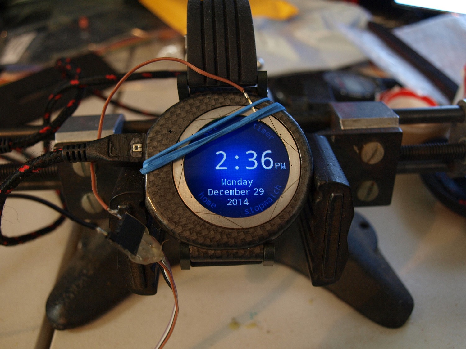
12/29/2014 at 22:08 • 0 comments![]()
Fun fact: Because of the capacitive touch hardware in the chip that the Teensy 3.1 uses, all of the Pi touch pads go directly to pins on the microcontroller. This means their functions can be reconfigured on the fly!
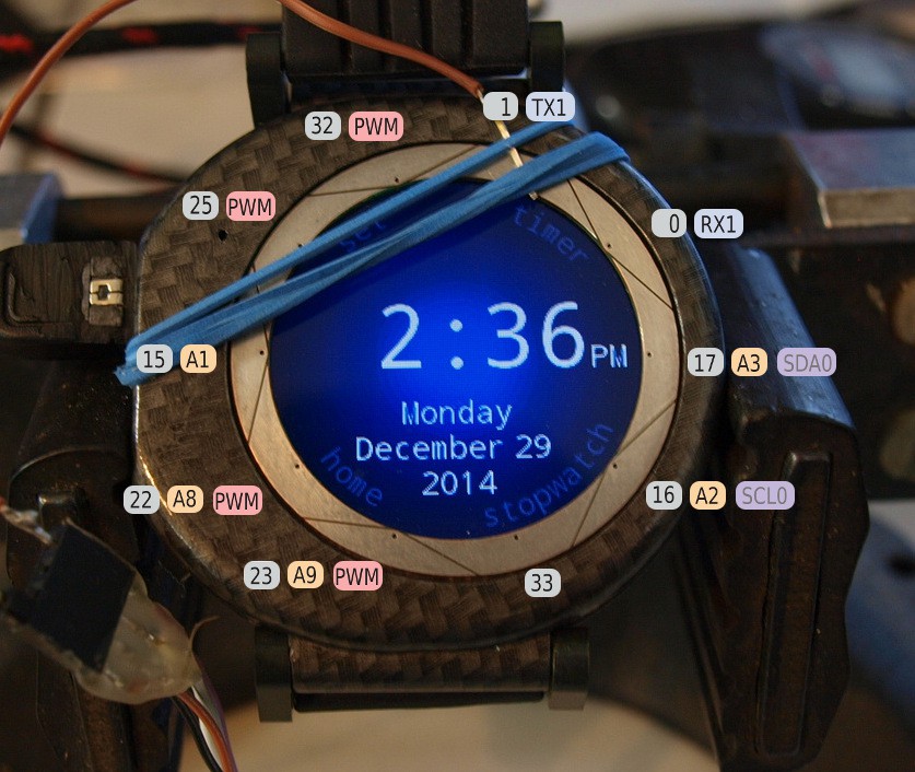
In case you didn't know, the Teensy 3.1 has some great low power capabilities. Unfortunately USB is no longer an option under 24MHz. That means that if we wanted to put out debug info while running at 2MHz (and if you are switching between two clock speeds, and plan to remain sane, you are definitely going to want to put out debug) the only option is a UART. Thankfully there happens to be a UART brought out on two of the touch pads! There's also 4 PWM capable pins, an i2c port, 5 ADC pins and of course they are all GPIO pins that you could use for bitbanging SPI or the like. Here's the pinout.
![]()
Of course the whole reason for this is getting the low power stuff working. My first attempt was just a timeout before it goes into 2MHz mode and dims the backlight. This worked fine until I tried adding in clock updates so that it could keep writing the screen even in low power mode. In the end I found a few places (mostly in the Time library) relying on millis() which in turn relies on the CPU clock. Once I fixed those and few other bugs in my code it's running beautifully at 2Mhz on the clock screen. All of that should be up on my GitHub now for anyone who is curious.
-
History - Part 2
12/24/2014 at 19:31 • 0 comments![]()
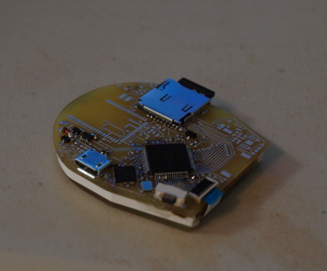
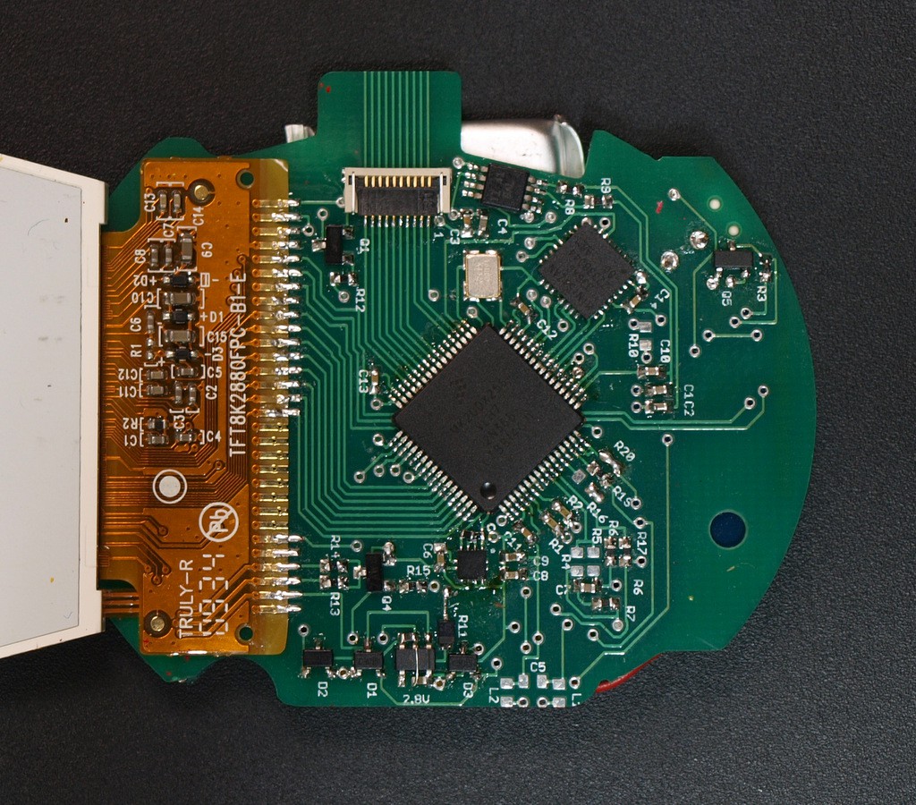
This board was the first real PCB we put together, needless to say it took quite a few jumpers and a blown Cortex chip before we had it all straightened out! This is pretty much just the bare board with the screen, touch ring and sdcard on it. If you look at our second PCB revision you'll see it populated with most of these parts.
![]()
![]()
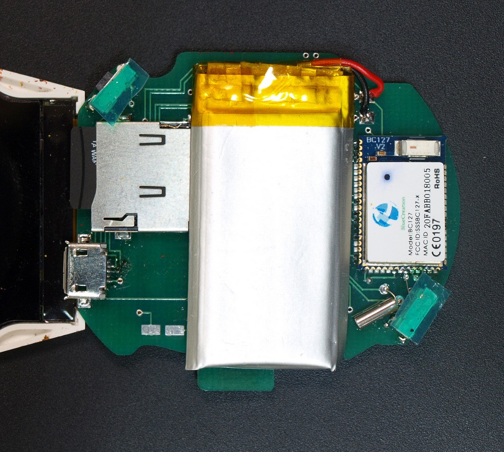
As you can see we also moved some of the taller components down to the back side of the PCB to reduce our stack size and still keep our 480mah battery right down on the board. You can even see the crystal for the RTC in the Cortex there. This is the first version that can actually tell time! This is also the version of the PCB that we have in the prototype currently.
Hardware Revisions
![]()
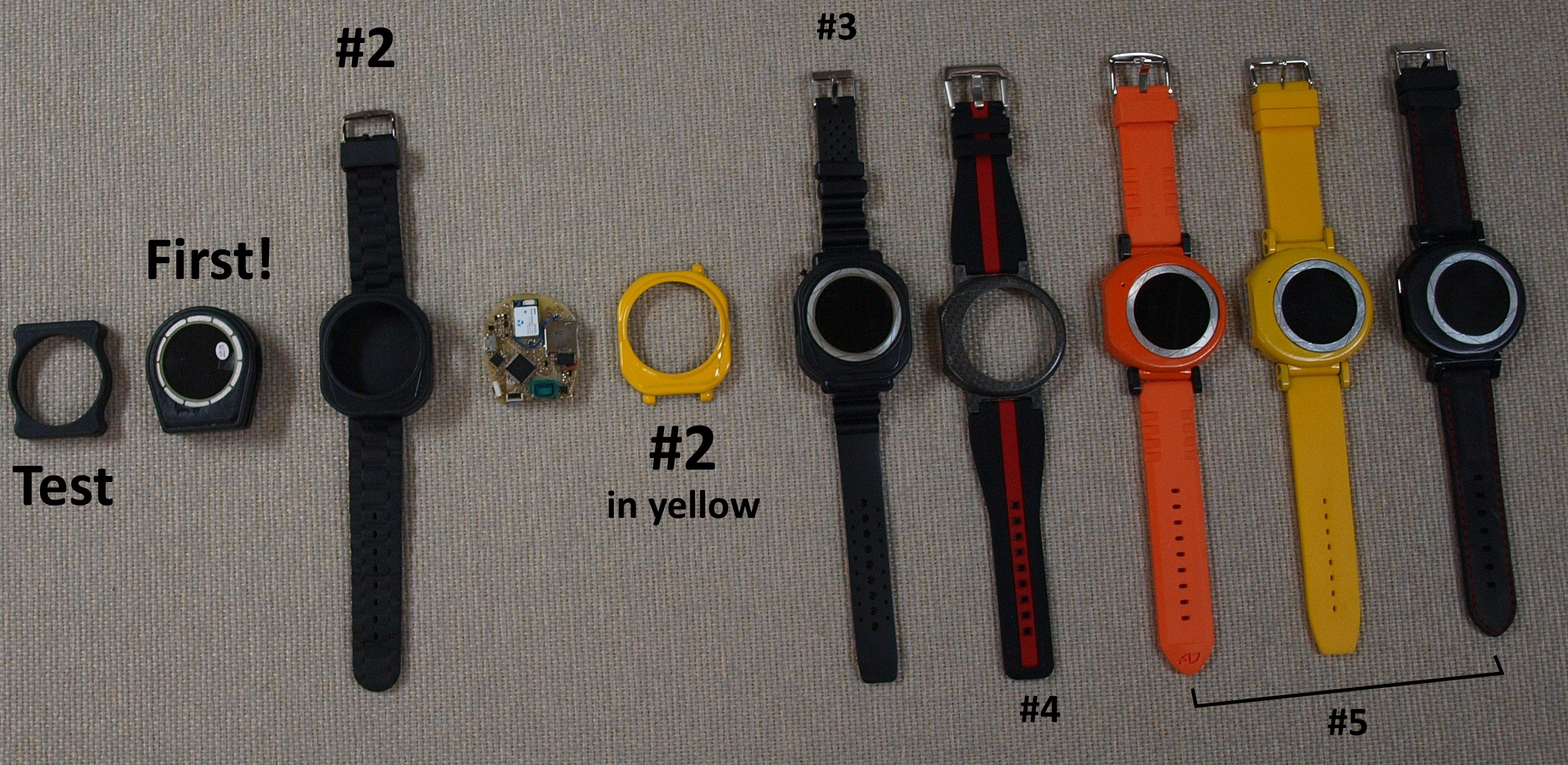
As you can see we've been through a couple iterations, and this doesn't count all of the designs we just threw out over the course of developing the case. Our really big 'aha' moment came when we rotated the screen 90 degrees to the right. We were able to make the case much rounder, and spread out the components enough to reduce the thickness quite a bit. The first case we were really able to fit all of the electronics in and get the watch band attached to was #3. Our last revision we also added the links for the band attachment which really helped increase it's wearability and let the band better conform to your wrist.
-
History
12/23/2014 at 04:54 • 0 commentsWell we are starting a bit behind so here's some history.
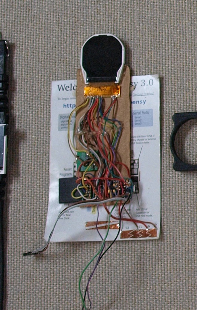
Who needs breadboards!?
![]()
This was the first real working example of the Pi Watch. You can see all of the elements here, the sdcard holder made from an old sd to microsd adapter, a bunch of sticky backed brass we cut up to resemble a slider, a connector that plugs into a develoment BC127 board and of course the Teensy 3.1 connected to the display. There also used to be a set of level shifters between the T3 and the display because the datasheet for the display said it needed to run at 2.8v and our T3 was running at 3.3v. The reason they aren't there now is because we were able to run the T3 down to 2.8v this means no buck boost converter when the battery is reaching the end of it's charge! (As I write this I'm also thinking that this could be the reason the Cortex was very much unhappy when we tried to overclock it to 168MHz at this voltage...)
![]()
The first real PCB!
To be continued... have to get up early and get to work on the faux carbon fiber watch tomorrow.
The Pi Watch
A watch with a Teensy 3.1 at it's heart. It's a Open Source development system that you can wear!