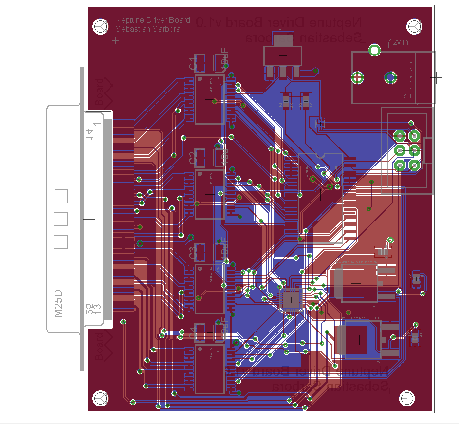
I finally got a board designs done and sent out to oshpark. I spent a bit of time working on the Driver board, which will control the motors, high power LED's, and servo's.
All of the outputs come out of a 25DB connector mounted on the edge of the PCB. This makes it a much easier and central location for attaching to the waterproof connectors.
A few other notable parts:
- 6 pin control connector, with high temp interrupt and I2C
- temp sensor to help with overheating
- Four 2 channel PWM motor controllers
- Two I2C GPIO expanders, one exclusively for controlling the logic of the motor controllers, one with PWM, for motor speed and servo control.
- 2 Mosfets for LED control
The Schematic:

The board:
 Bash Sarbora
Discussions
Become a Hackaday.io Member
Create an account to leave a comment. Already have an account? Log In.