 Tyler Sisk
The hardware for this project was designed to make the software much easier to write. The main goal of the device is to provide the 40Hz signal to the electrodes at a certain times in the morning specified by the user.
Hardware:
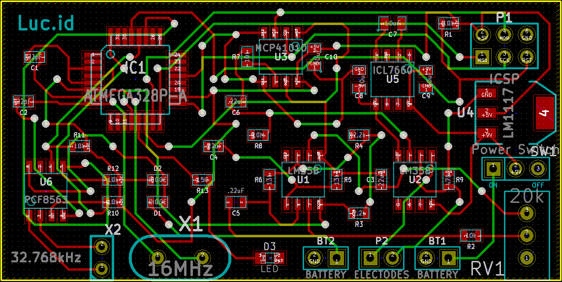
Microcontroller - Currently using the ATMEGA328p doing basic things such as reading the RTC turning on the oscillator, controlling the digital pot. Uses the external 16MHz crystal
Oscillator - There is quadrature oscillator using two op-apmps located on one of the lm358's. The oscillator is designed to generate a 40Hz sine wave which is then passed through the digital pot and eventually to the current regulator. The frequency generated is tuned by the 20k pot.
Digital Pot - used to control the amplitude of the signal. It allows the current through the electrodes to 'ramp up' slowly so that the wearer is not woken by a sudden application of current.
Current Regulator - regulates the current through the electrodes. I designed it to supply a current of 2mA when fed a 1 volt signal. This uses one op-amp located in the other lm358.
Real Time Clock - using the pcf8563 because it has alarm capabilities, which are used to wake the microcontroller from sleep. This allows the user to set a time for the device to wake up and send the current through the electrodes.
**Make sure to check out the GitHub page to get all of the files that I have been using for this project including:
- Schematic pdf and the actual .sch files
- Board files for KiCad
- Bill of Materials listing all parts with some links to Digikey parts
- All code I have been using
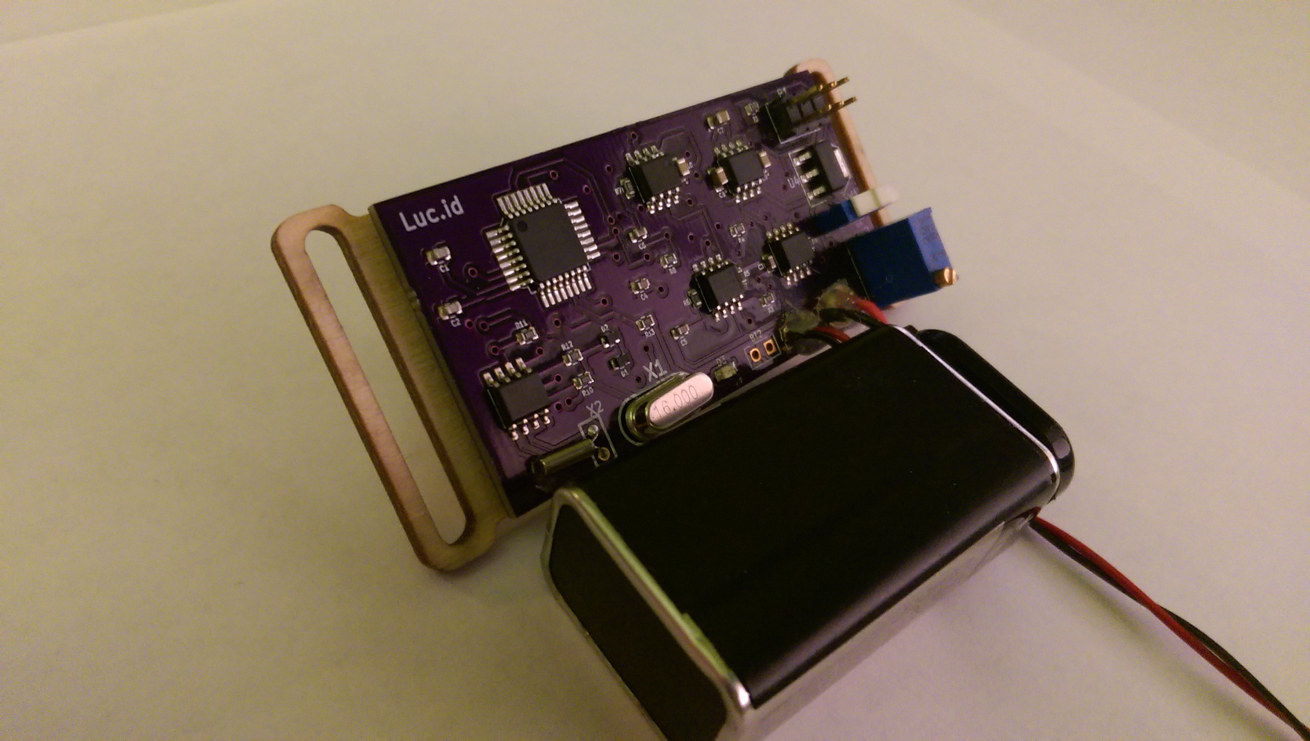
Here is a nice picture of the RevA board. I just fixed the only problem I found on the chip and am waiting on the boards to come in from Oshpark and then I will make the final RevA for testing.
Software:
I am using arduino in this project because there are already libraries available for the RTC and I am lazy. The board is programmed via the icsp header in the top right hand corner of the board where the top right hand pin is the ground pin. You will need a programmer such as a USBtinyISP from ebay, any avr programmer that can program using a 6pin isp port will work.
After the board was created I burned the arduino bootloader onto it in the arduino ide, then any code can be uploaded by going to file - upload using programmer. In tools, the board is Arduino Dueminlanove w/ Atmega328, and the programmer is whatever programmer you are using in my case the USBtinyISP.
Again all software will be available on the GitHub page that is linked on the left of the main project page. If you can't find it my name is breadboardbasics on GitHub and the repository is called Lucid.
Also in my opinion the current limiter was the hardest aspect of this project so far. I posted a thread on physicsforums about it. If you are interested my name on physicsforums is HHOboy. Here is a link: Forum Thread
Please let me know if you have any questions or feedback about this project. This is my first time using Hackaday and GitHub so I am still finding my way around. Thanks for looking!


I too wish this project would get another update. If not, it would be great if we could get the schematic to edit/finalize.