MasterOfNull
-
Hot-end, v9.... works.
03/12/2016 at 18:25 • 0 commentsThis will be a short update, as the next one will be... good.
Started over with my all metal design.
Changed a few angles and dimensions. The issues I had with v8, the plugging and jamming during cold starts, are gone and I was able to keep all the good stuff. All metal, less parts, easier to produce, very happy.
Correcting the rounded corners issue, which was a tool accuracy gcode setting, has revealed another issue. The test cube I've been printing now comes out with the top evenly shifted towards the back/right. I believe this means I'm loosing steps on my B axis during fast upward motion. When I go to print the next part, the head also slams into the bed if I don't re-home. I'll be tuning my drivers and tweaking my acceleration and max velocity settings today. I've never done this correctly and I've been living in the world of 'good enough'.
In other news, I got to try actual CYMKW printing after a trip to Coex resulted in 5 spools of suitable filament for testing. Got a pretty good looking full color spectrum, but the saturation level (and balance) of the filaments requires some significant tweaking. Getting a pure blue for example is off by ~50% from where it should be, and ends up looking dark and muted.
So, I drove back there yesterday and tried RYBKW on-site. The color saturation was much better, but so was the color saturation of the source filaments. Obviously I could produce a pure blue now.
I'm thinking it comes down to mainly the saturation and color balance of the source filaments. As I just grabbed the filaments they already had and it really wasn't designed for this, nothing I'm using is a real 'pure' color. My magenta is too white/red, my cyan is actually aqua and seems to have black in it. My yellow also contains a lot of white. My red and blue both contain black.
All these colors are designed to be visually appealing on their own. They are not designed to be accurate or balanced.
Ideally, the source filaments should be fully and evenly saturated, and not include black or white in the mix to the extent possible. This would probably not make for good looking filament on it's own, and would require a significant investment on the part of my filament supplier to correct. I'm going to solve this to the extent possible in software first, so I can have some quantifiable results. There would also need to be a market for it. Working on that..
-
Hot-end, version 8.... sucks.
03/05/2016 at 02:38 • 0 commentsBreaking the mixer shaft forced me to disassemble version 7. It had leaked around the screws that lost AL in the last assembly. The mixer seal was still in perfect shape with no evidence of leaking even while I was feeding it without it spinning. That's really good news.
Decided it was time to make another one.
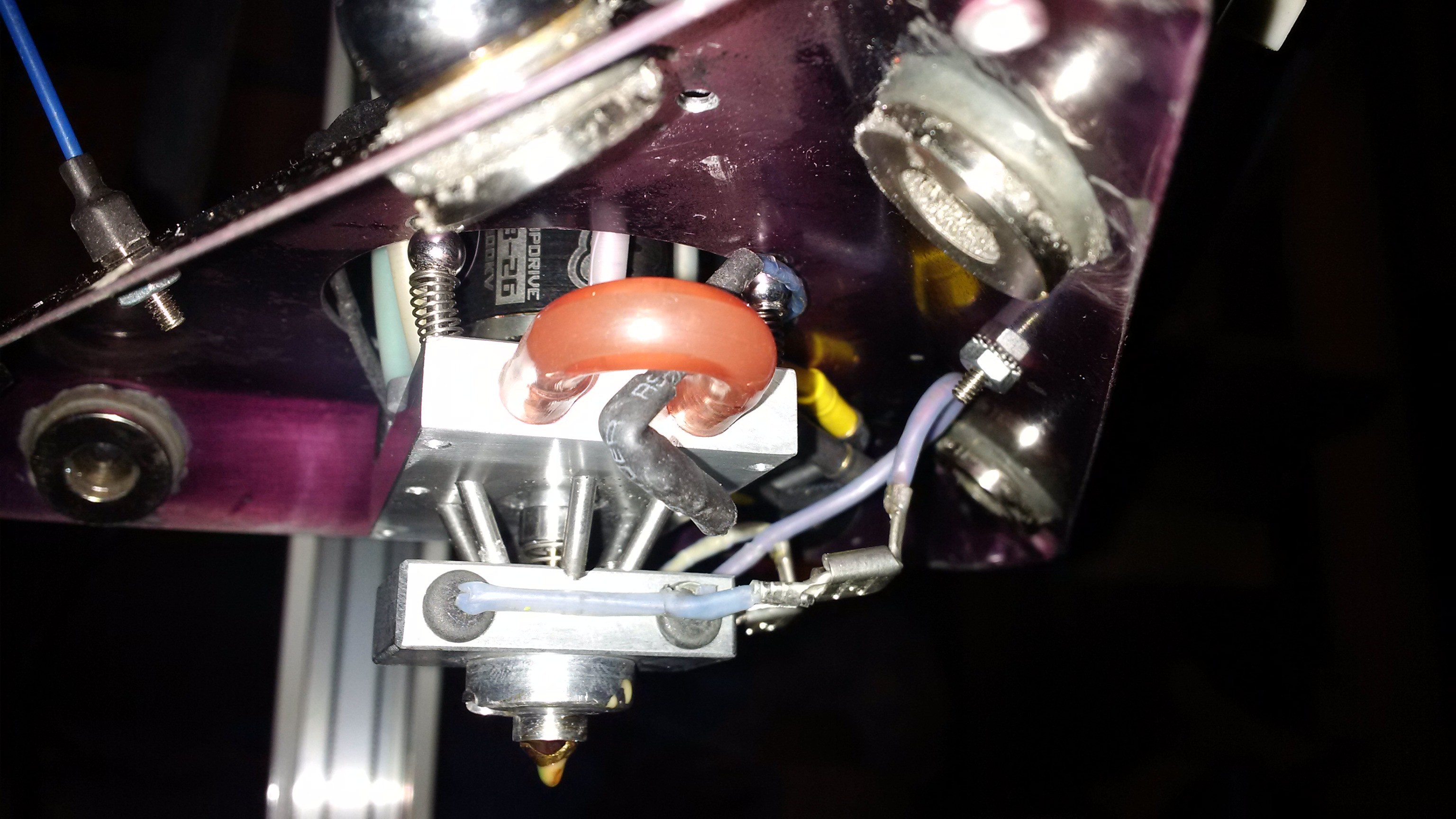
Designed and built an all metal version.
![]()
![]()
- Eliminated 14 parts.
- It's cheaper to make.
- The tolerances required are more lax.
- Reduced thermal losses.
- Mixer is half the size.
- Mixed volume is 1/4 what it was.
- You can take it apart without removing the resistors. :)
- You can align the mixer motor without taking it apart.
In the negative column, it required a press and building an assembly jig as much of it was press-fit together. The previous version you could put it together with a screwdriver and two allen wrenches.
It worked great the first day! Just ran some garbage white PLA I had through all 5 channels to clear out the machining remnants. Sealing was perfect. Feeding was fine. More torque required to push, but still manageable. I also decreased the size of the tubes feeding the mixer, and decreased my nozzle size, so it is hard to tell if increase in torque required was related to the 'no PTFE liner' bit or not. If I was building these with CNC, I would probably change one variable at a time. :) That day is coming..
I ran it for a couple hours with no issues.
Came back out today to do a color test. Three of the five feed tubes were jammed. Two were jammed badly enough to require removing the bowden tubes to clear them. One jammed again even after cleaning.
I think the issue is my tube size for my all-metal design. All I could find in small diameter stainless tubing locally was ~2.1mm ID. That leaves a good gap around my filament for the 'piston' to creep back up the tube into the cold area, as I also didn't provide an interior taper in the hot-end area. My feed tubes were also not polished. I was just hoping for the best, but expecting the worst. The worst happened.
The same thing basically happened with my PTFE liners which were ~2.0mm ID. There it didn't matter at all though. The PTFE gives a little and the cold start obstruction just pushes into the hot area and clears without you ever knowing it was there.
A friend of mine with Amazon Prime ordered some correctly sized tubing for me so shipping wasn't more than the part. (Thank you Ezra)
I get to try again in 2 days.
-
Hello heated bed, goodbye mixer
03/02/2016 at 04:31 • 0 commentsConnected to the printer it so I could remove the filaments stacked on top to get at the guts. The software was still running, and had been running for the last 4 days. That is a good thing. Guess I don't have any memory leaks.
When I last disconnected, I was feeding filament to figure out why my one stepper was not pushing and hit the e-stop button to shut it down. What... you don't have an e-stop button?
So when I toggled the e-stop, it started feeding, which powered my mixer. As the hot-end was stone cold, with the mixer embedded in solid plastic, snap went the shaft. I hate it when I'm right. Adding the code to prevent this has moved up the list.
The good news is my heated bed works, well. Perhaps a little too well. I am fairly certain that the battery I used for testing was not delivering the required current. It was a flooded lead acid battery of sufficient size, and it did read 12.6v at the start, but I did not test the output voltage under load.
I held the leads to my power supply output to see if it would just shut down under the load. It had no issues supplying the current, with everything else powered. I continued to hold the leads there, and in about a minute my power supply had slowly turned into a jet engine.
A few minutes later the massive solid stone heated bed was at 70C, and my 8 gauge supply wires were slightly warm. If my leads are heating, I'm fairly certain my T-220 case style mosfet would pop under that kind of load. I'll add a couple more so they can share it.. Now I wonder where I'm going to get a thermal fuse rated at > 40A? I will not be running that, unattended.
I had put another round of furnace cement on the bottom, encapsulating some steel washers I had ground to level it out. The stone varied in thickness (on the back) by almost 2mm. I should have probably measured that earlier. So... I continued heating it up to 100C so I could cure the new cement.
With an IR thermometer, I measured the surface temp at various points. The center was the warmest, with the very edges down by about 10C. At 100C I'm probably getting convection cooling. The vast majority of the build surface varied by less than 2C. I'm calling a 2 percent deviation a success.
-
Heated bed, almost
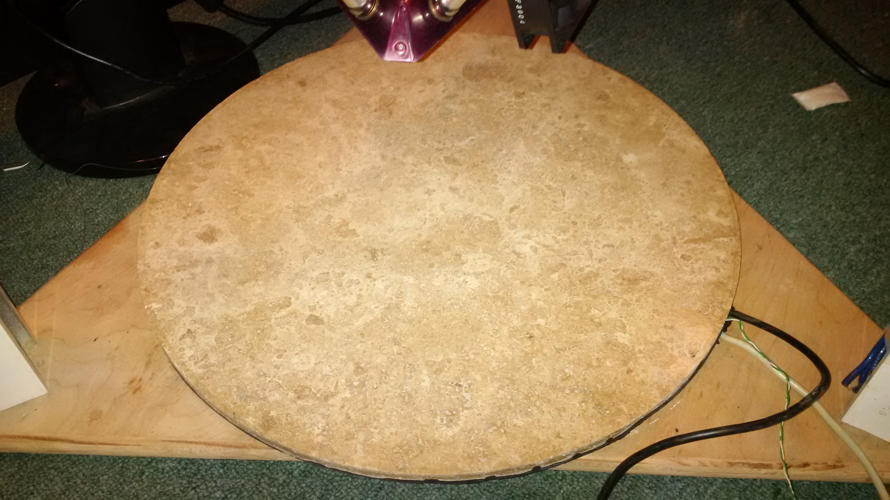
03/01/2016 at 06:01 • 0 commentsI built a new 240w/480w, 450mm diameter heated bed from a stone floor tile, a network cable, and some furnace cement for < $20.
![]()
I gave it its own project as it hasn't burned up yet..
Minor rewiring and more furnace cement are still needed to permanently switch it to 480W as my initial resistance calculations were off. It doesn't make enough heat to be useful at 240W.
My server power supply and the bed power mosfet can handle it, but other stuff will need some changes. When I built it, I guessed I would need a < 360W bed and wiring/fuses/heat sinks were built to handle that. At that output, I also may need to drive my power mosfet harder. If it gets hot (or explodes), I'll need to add an amplifier in front of it. I'm decently above 'on', but well below 'max' for the gate voltage of that mosfet.
I also currently have zero disconnects rated for 40A, and I want it to be removable, so I'll have to figure that out.
-
Homogeneous ABS + PLA
02/27/2016 at 19:09 • 0 commentsTook it to the makerspace 2 days ago.
I made it too large... it barely fits in my car. I think a 400mm cubed print volume was a bit ambitious for a prototype.
After about 1.5 hours of manually re-calibrating it from banging it about and adjusting the wrong values, I got some prints.
The new seal is working perfectly with no leakage for ~12 hours of running as of now.
The mixer runs about half the speed it did un-loaded. The mixer speed slider multiplier range was adjusted accordingly.
I took the print head up to 250C for the testing with no ill effects.
Mixing works, and is perfect.
Four of the five filament drives worked. Two needed current tweaking to push. One is running hot at ~50C even with liquid cooling (I think the current adjust, isn't adjusting so my 1.4A stepper is being driven at 2.2A). One sounds like it has a blown mosfet, but still works well enough to push.
One won't grab filament anymore and needs looking at.
We only had a very small amount of black PLA, so on a whim I loaded black ABS (from a newly opened spool, so yes... it was definitely ABS).
It made perfectly blended grey extrusion, was strong, bonded to either ABS/PLA, and I have a makerspace full of witnesses. :)
Yes, I know they are chemically incompatible. Yes, I know that it shouldn't work... but it does...
Temp, set at 220 - worked, but mixer speed audibly decreased when feeding the ABS.
Temp set at 235 - worked.
It bonded well to itself and the bed (eventually), and to straight PLA/ABS as long as the mixed material was in between.
It would not bond to my bed, until the bed was heated with a heat gun and sprayed with hairspray.
It oozed, probably from running the PLA well over-temp.
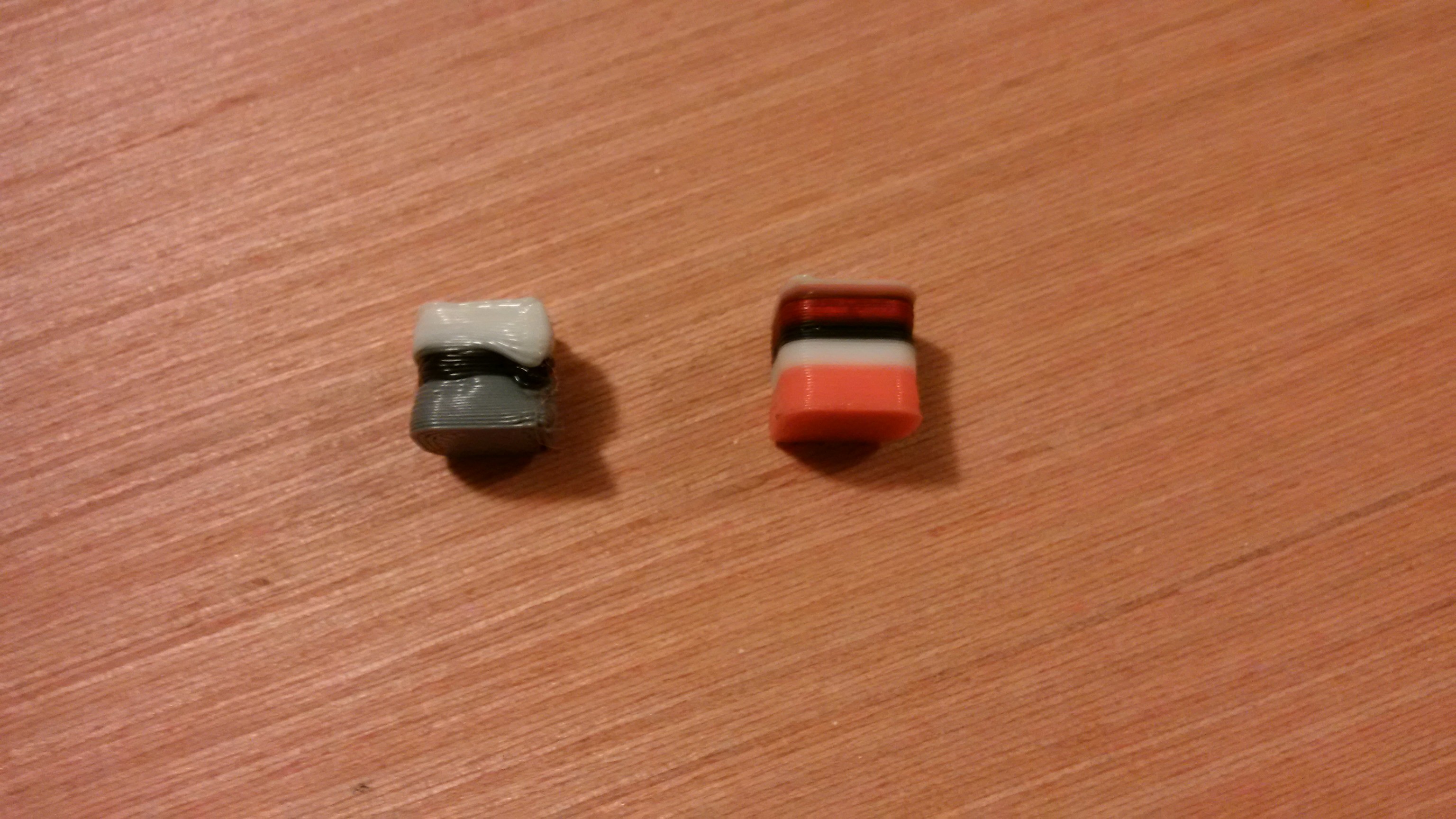
All the prints are ugly, but for other reasons.. :)
![]()
I didn't have a fan hooked up, so the first ones 'melted', probably because I was printing a really small test object at 60mm/s. Slic3r wanted to turn the fan on... it just didn't exist.
The print on the left, the grey is black ABS + white PLA at 30%/70%, then straight ABS, then straight PLA.
When I did rig up a fan, the PWM drive signal was absent from the mosfet (floating input, so guessing not hooked up). When I hooked it up to just always be on, the hotend (with no shielding, directly in the path of a full speed 2.5in server fan) could not get above 210C even with 80w of power. I have live, uncovered connections under there so rigging up some tin was not tried.
I manually turned on the fan during the print on the right, so it started at temperature and fell slowly enough to get one done. The pink is red + white PLA, then white PLA, then black ABS, then red PLA, then as the last layer printed I switched it back to white.
I had some software issues with arc blending/path smoothing (the CNC roots of Machinekit) so all my mid-path sharp corners are round. I discovered it was adjustable via gcode, so I think I have that sorted.
Bonding to the bed was tricky to impossible. After all, it's just a fake marble ceramic floor tile. It worked *much* better after heating it with the heat gun. Making it a real heated bed is happening today.
-
New ESC firmware
02/25/2016 at 17:54 • 0 commentsI was still having problems with getting a linear, low RPM response from the BLDC ESC.
Re-flashed the simonk firmware on the ESC. I reduced the stop pulse width to 100us and disabled auto-calibration.
I spent far more time figuring out how to use my new no-name programmer than anything else...
Settings I used are in tgy/tgy.asm in the github repo.
This gives me a much larger range of pulse widths I can send it now.
The valid PWM range (at 400Hz update rate) for a happy ESC on startup is now 0.025 to 0.037, it starts spinning at <5% above that, and has a pretty much linear response for the range I need.
Good enough.
-
Not laggy ECS's
02/24/2016 at 04:23 • 0 commentsThis is what it should do.
Mixer spins in lockstep with current extrusion rate, which is calculated from print head velocity.
I've slowed the mixer speed here so you can see it spin and it has time to stop between lines.
Not printing anything here. Just going through the motions.
-
New ESC and BLDC motor
02/23/2016 at 21:58 • 0 commentsESC and motor got here right on time yesterday morning. Hobbyking is awesome.
Assembled everything last night and powered it up. Everything fit on pretty much the first try and no_smoke.exe appears to be functioning.
![]()
![]()
My wiring inside the stepper carriage is getting embarrassing. I think perhaps if there is ever an M2 version, it should use I2C to interface everything on a little dedicated pcb.
Altered the floating stepper carrier to just attach to the rail carriages instead of using a line to the back side of the drive belt after I snapped two of the 1.7mm nylon lines in a homing mishap. It works pretty much the same and it's simpler, albeit noisier and more load on my carriages, bearings, etc. It will work for now.
I have not implemented I2C communication to the ESC yet in software, so I wired it up using the PWM channel.
Changed the beaglebone to use direct Ethernet instead of going over the emulated USB Ethernet. Some issues disappeared, and everything is faster. I think they were client side issues actually, but fixed is fixed.
My plan to use a defunct router as a wifi bridge was thwarted as neither of my junk wireless routers are flashable with anything useful. Using the USB port on the beaglebone for high traffic things like networking causes issues so I'm hesitant to plug in a wifi adapter.
-
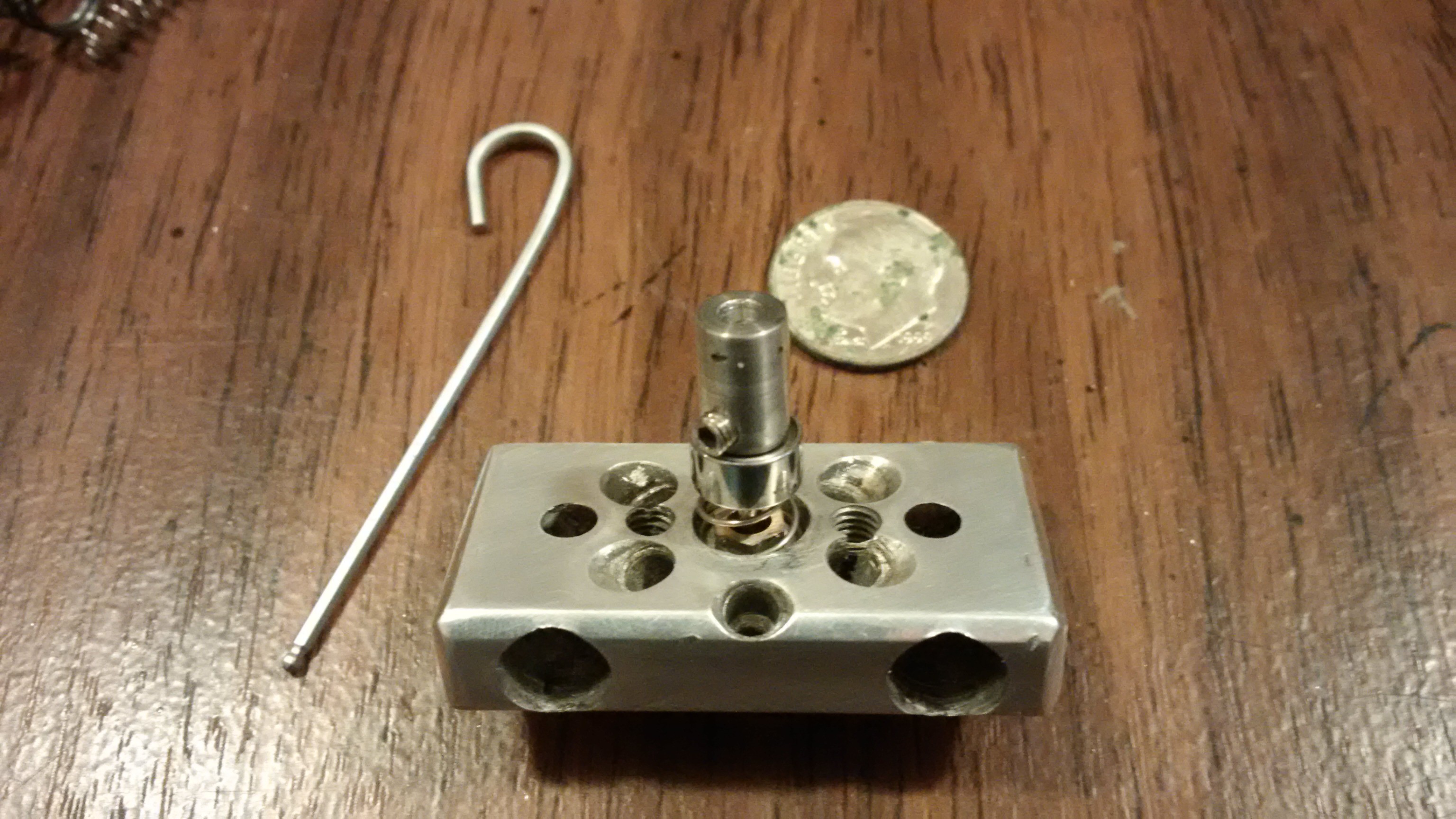
Mixer seal, take 25.
02/22/2016 at 02:00 • 0 commentsI don't know that is is take 25, but there has been a whole lot of them.
I've got a really good feeling about this one!
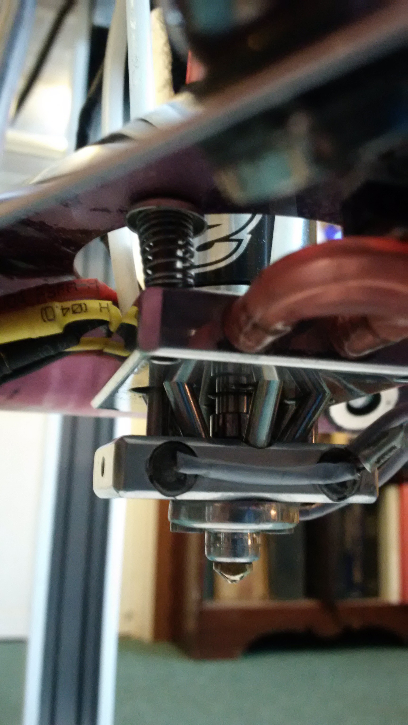
It's tough, the seal portion is self aligning, and I was able to get some pretty good tolerances (with iteration).
This one pulls on the mixer shaft with spring tension not transmitted through the impeller drive motor like some of the previous versions, so no more spending hours modifying motors and aligning them. It will be flexibly coupled to the quad motor with a pin/slot drive, and is tightly coupled to the impeller with a set screw.
![]()
I drove it 'dry' with my drill press at 3000 rpm with no lubricant for a couple minutes and it didn't self destruct or eat the seal. That's a lot better than some designs I've come up with. :)
The stainless steel impeller drive shaft size was reduced from 2mm to 1.15mm as I needed to increase the sealing surface area. On initial testing, the spring tension needed to self align was too high for the smaller surface area seal and instead of aligning, the seal ate itself. I do have some reservations about the smaller size shaft. An accidental cold startup of the mixer drive motor could result in a snapped shaft now. This is a real possibility as there is a bug in the software which causes the mixer to spin while homing after printing. I'm looking at decoupling the drive signal until at operating temperature the next time I'm in 'software developer' mode.
The bearing I scavenged from a large, high output, PC fan so it should withstand the axial loading for a good long time.
The seal in this version is glass fiber reinforced PTFE encased in brass, which was pre-compressed while at the upper temperature limit for the PTFE. (actually, I just cooked it with a lighter and pulled on the shaft) Why? The first time I heated each virgin seal, they would creep significantly and my mixer would end up being recessed by about 0.4mm. There it would stay for the most part, so to move it back to where it should be, I made it adjustable. The adjustment screw was in the way for this version, and you couldn't adjust it without taking the whole thing apart anyway, so it went by-by. The glass fiber reinforcement also makes the PTFE a lot stiffer, at the expense of increased wear which has yet to be quantified.
The new impeller for this version has a brass sealing ring which, despite my best efforts at fixing it on the shaft with extreme temperature differentials, popped off while I was trimming the impeller shaft to size. After a couple of attempts at machining an all stainless version, I gave up and put the brass one back on. It doesn't spin on the shaft without plastic in the chamber, but it might with...
The new ESC and a slightly beefier BLDC motor will be here soon. The previous motor had plenty of power, but I'm thinking that the larger motor should respond more linearly at low RPM. The old motor had a 3.1mm shaft, while the new one has a 3.0mm shaft so I haven't been able to do the final assembly or any real tests. I'm patiently waiting as my motor makes its way here from Arkansas.
One significant issue has presented itself. I did not have sufficient clearance between my PTFE feed tube passages and the bolt passages which retained the nozzle. While I was disassembling it after the last run, I allowed it to cool too much and some PLA which had made it's way onto the bolts took some of the AL with it. That's 6061 T6 aluminum which was just relocated by plastic. I cleaned the bolts and tapped out the ports again. I still have enough force to seal the nozzle, but it may leak now and the only fix will be to machine a whole new part. This was another time consuming side effect of being low on thermal compound, which also seems to work pretty well as 'anti-seize'. The bearings in my drill press are now making an intermittent 'replace me now' screeching sound, but as I've been abusing it with lateral loads for a decade, I can't complain really. I'm just going to run it like it is, until it leaks badly enough that I can't. Moral of the story? Don't cheap out on thermal compound.
-
Laggy RC ESC's
02/17/2016 at 00:10 • 0 commentsGot around to finishing the software to drive the RC style speed controller.
It lags... terribly... even in it's 'fast' mode. It seems to be averaging the input signals before generating things. So on the start of a line, it spins up late. On short lines, it doesn't spin up at all.
It also obviously switches it's MOSFETs in the audible range making for a pretty annoying printer.
I got excited when I started looking around for alternate firmware. Lots of work has been done for flashing crappy ESC's to perform better. I figured out which ESC I had and checked for a better firmware for it. Alas it has a SiLabs chip, and BLHeli doesn't support it. I'm basically out of luck.
My attention turned to the quad motor. It has 12 poles. My initial thought was to rewire it to be a bipolar stepper and drive it with a stepstick. Well, it also has 14 magnets, so it needs the three phase drive to keep things spinning. That's a dead end as well.
Hobbyking had a decent 20A ESC already flashed with the SimonK firmware. It supports 1khz update rates, has OneShot125 support for zero lag, and has an I2C header I could use as an alternative to PWM encoding. At $10 shipped from the US, I'm investing in one.
Arcus-3D-M1 - Full Color Filament Printer
Active mixing, fused filament fabrication 3D printer.