 deʃhipu
-
1Step 1
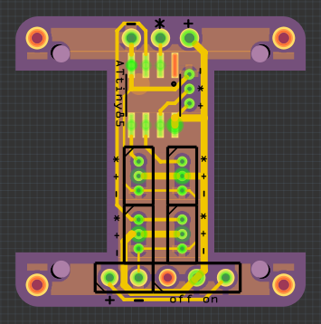
First, you will need a PCB. There is a Fritzing file in the repository, which you can use to generate the gerbers and order it, and here is an OSHPark order you can use: https://oshpark.com/shared_projects/qjZ6fhAS
![]()
-
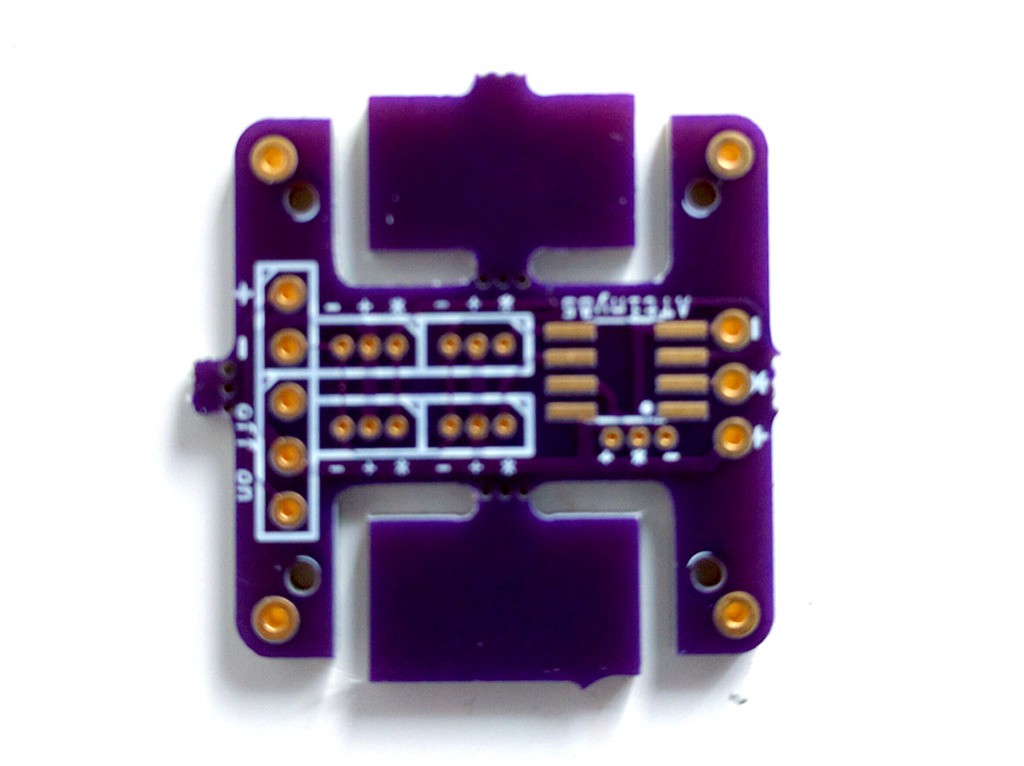
2Step 2
Once the PCBs arrive, you have to cut all the excess pieces, and polish the resulting irregularities. Depending on the servos you have, you might also need to file the PCB a bit to make them fit well. My servos fit exactly right, with some force, but you never know.
![]()
-
3Step 3
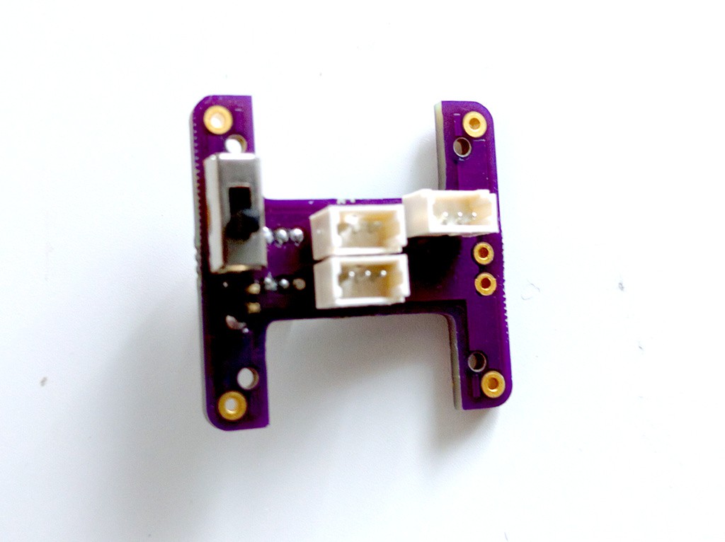
Assemble the PCB -- solder the switch, the power socket, the servo sockets, the chip. Make sure to put two of the servo sockets on one side, and two on the other side -- so that you don't have to move wires through the PCB.
![]()
-
4Step 4
Before you attach the servos, program the chip using a programming clip. You will need to remove and disconnect the servos each time you are reprogramming it.
-
5Step 5
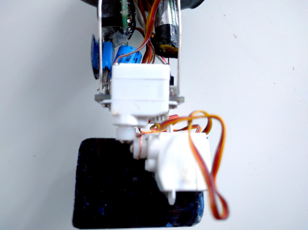
Assemble the legs. To make knees, take two servo horns, heat them with a lighter, and press them together -- they will fuse. Make sure you make something like this:
![]()
-
6Step 6
The feet are cut out from a piece of plastic and simply glued to the leg servos.
-
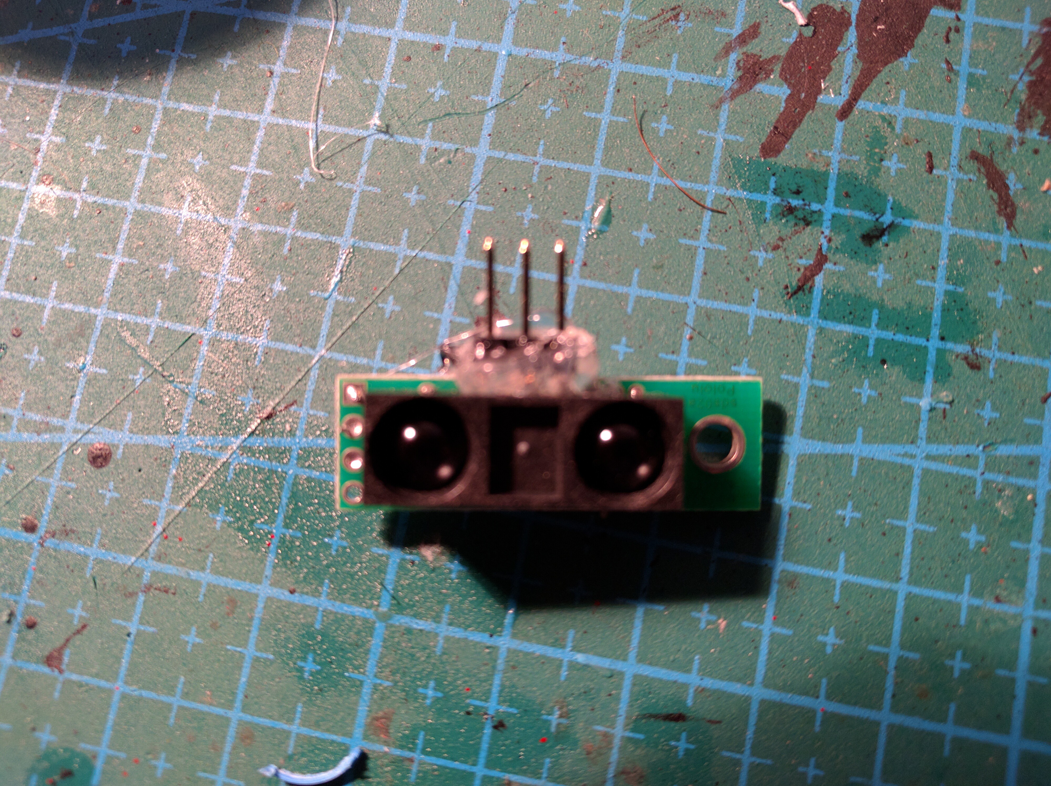
7Step 7
For the distance sensor, use hot-glue to add a 3-pin header to the bottom:
![]()
And connect those pins with short wires to the sensor's contacts.
-
8Step 8
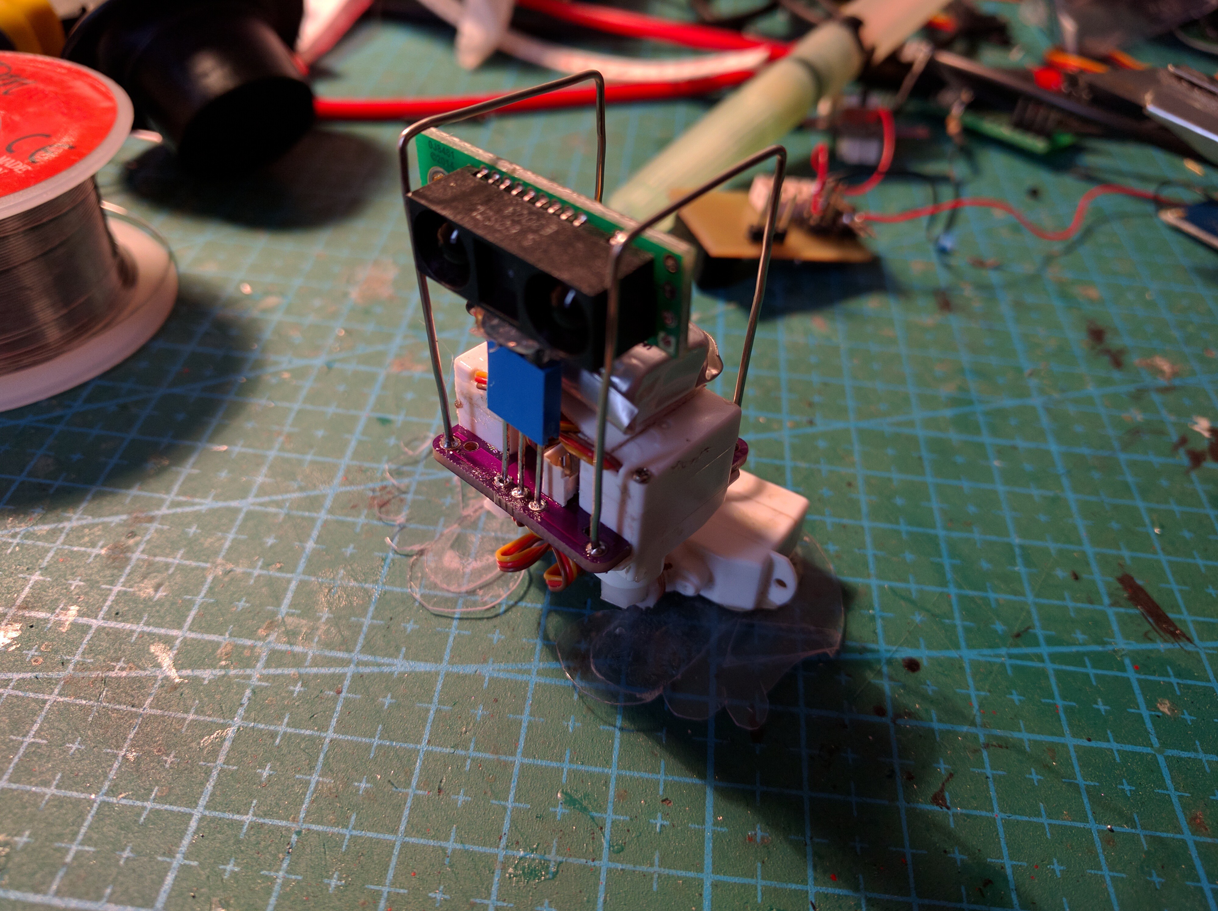
Then use a stacking header to attach the sensor to the PCB:
![]()
-
9Step 9
For the body frame, bend some paper clips and solder them into the holes in the corners of the PCB:
![]()
-
10Step 10
You can add a hat, a mustache, some wire hands, perhaps a pipe or a monocle, etc. The battery is attached to the frame with some two-sided tape.

Discussions
Become a Hackaday.io Member
Create an account to leave a comment. Already have an account? Log In.