-
conclusion and loss
03/24/2015 at 14:54 • 0 commentsAs a proof of concept it worked. Even though the optic was somewhat unresponsive (because it didn't fit compleedly planar). Biggest backdraw was that I misplaced the wheel (too much in the front, couldn't reach is with the thumb).
Sadly I can't provide pix from that for "fail of the week", because I lent the thing to a friend, who claimed it fitting for him and wanted to use it. Old as I am I can't remember who it was...
So maybe I do a version 2 some time.
-
case fitting
03/24/2015 at 14:50 • 0 commentsNext was cutting the side facing hole for the wheel:
Mainly by a dremel style tool and some marking before, but ended up just bigger than I liked.
And I hat to cut some parts of the metal (see above) and some material in the top case part to get it fitting.
strain relief for the cable done by a cable tie (original cable had it molded directly onto the cable, the USB one was done with some in molded clips):
-
The scroll wheel (part2: new position)
03/24/2015 at 13:38 • 0 commentsTo fix the wheel in it's new position I needed a method to hold the wheel axle in position. One side is just a hole in the PCB (tehre are large areas only ossupied by the ground layer, so no harm, if a little hole is missing (position was marked before):
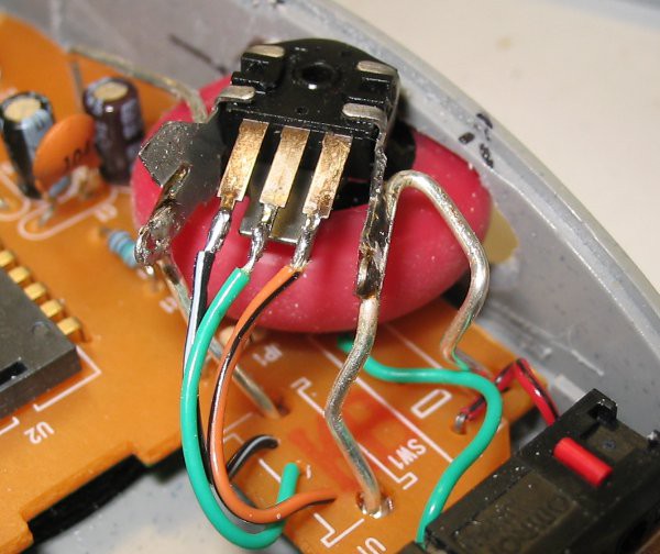
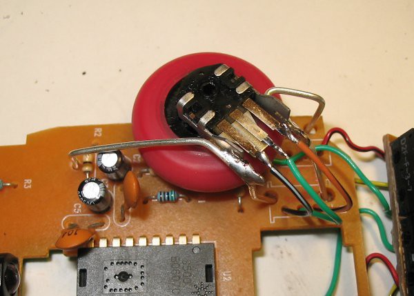
The other side is fixed by using the original decoder part, which I fixed in position with 1mm copper wire (silver coated). soldered in the previous holes of the ground pins and in new holes I drilled into the ground layer (and removed some of the coating):
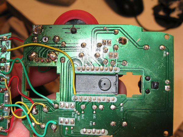
Contacts are bridged with some wires. A short test proved everything electrically functinal. -
The scroll wheel (Part1 prepare the axle)
01/22/2015 at 12:48 • 0 commentsWell thats the difficult one.
To understand how the wheel/button combination works I recomment to look t this in-dedatil dercription of a teardown:
http://eehomepage.com/report.php?report=20080214
(figure 11/12 are very helpfull).
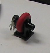
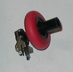
So having the button already re-wired to the middle of the SGI ones (see previous log), I had to find a way to put the scrollwheel somewhere else and I'd allways like the ides to have it faced sidewards (for me as right-handed person to the left). The orignal axle of the wheel is quite long, at least much to long to fit vertical inside the mouse:
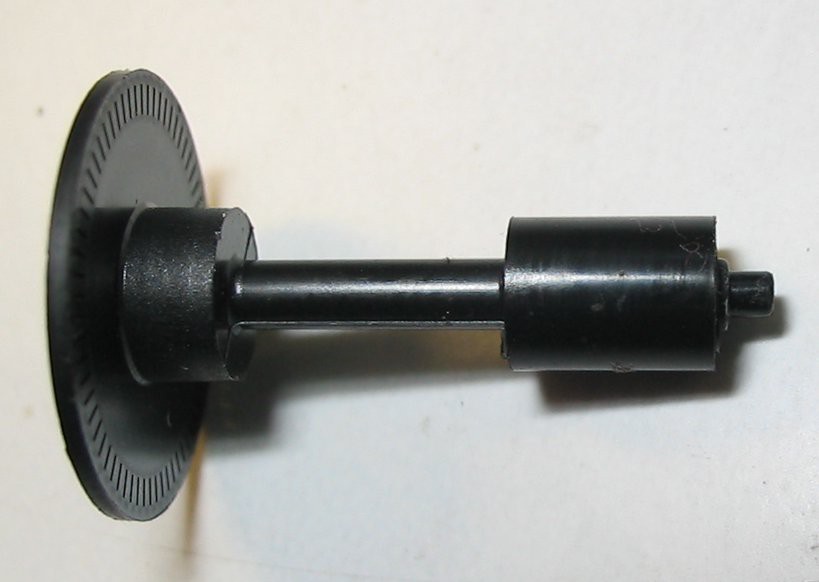
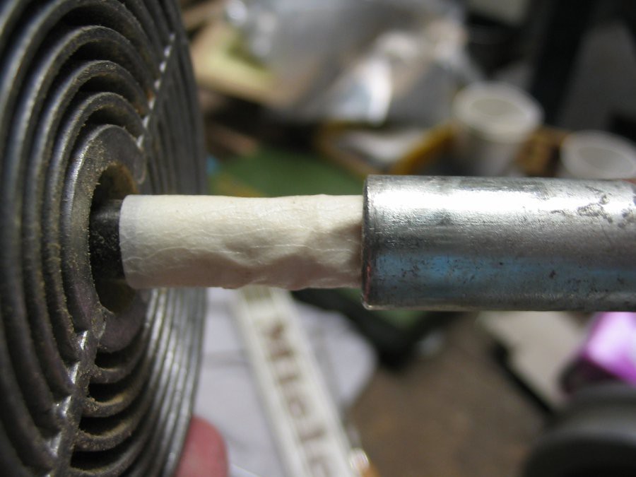
So here is some fitting to be done. While I could use the left side withe the decoder to holde one side of the axle I had to find a new support for the right side, which could be an easy hole in the original PCB, because there was only a big ground area in the place, where the axle should go. BUT surely not one with that big diameter, so I started to build a new axle (turning down the orignal wouldn't work 'cause it's hollow one). Fortunatelly the axle of the ball mouse had the same outer diameter as the inner diabeter of the scrollwheel axle, but the other side oof the scrollwheel axle was to long also. Here is howI solved that:
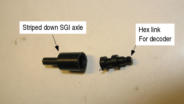
Getting the needet parts: 1. the hexagonal part of the original axle:
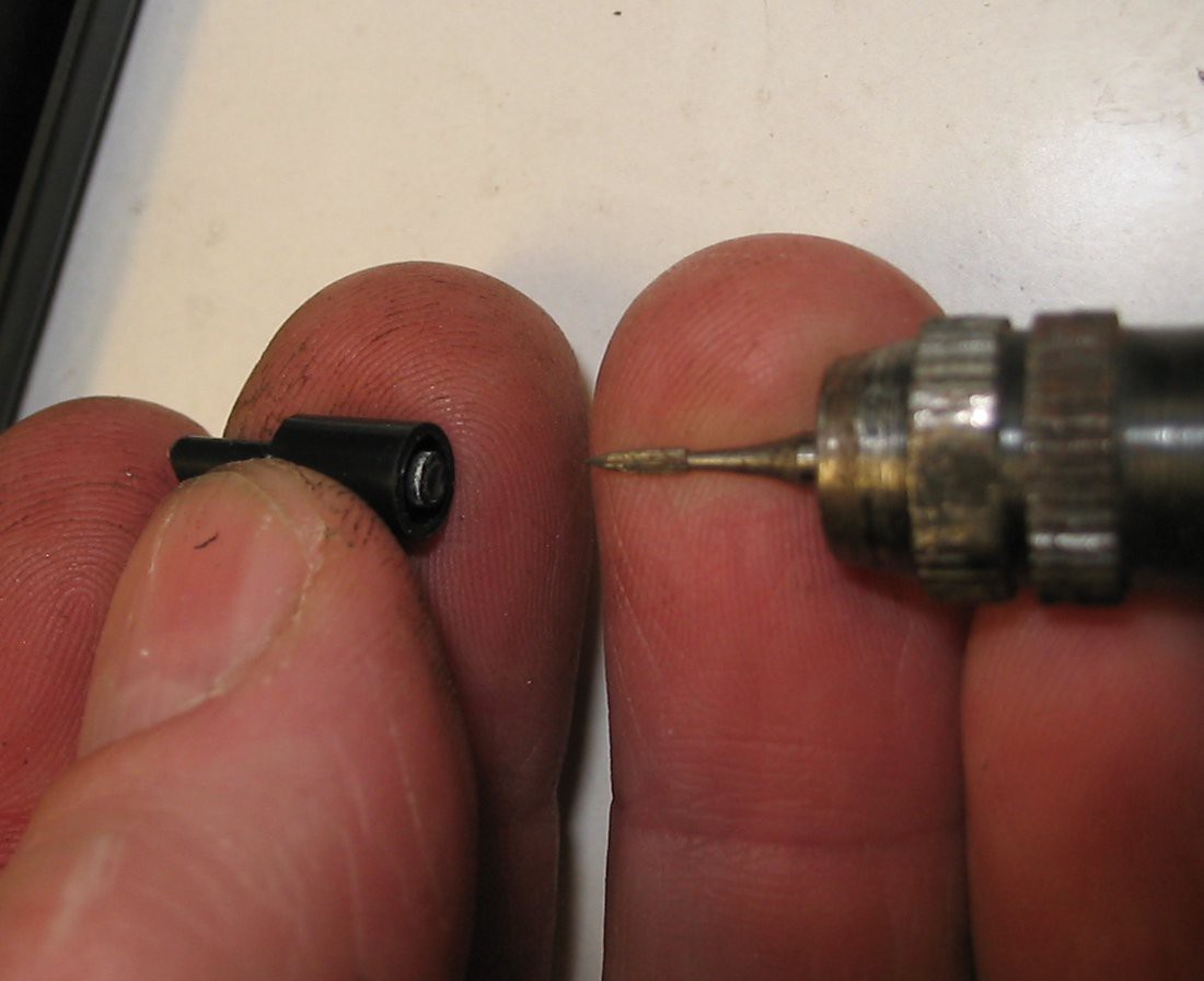
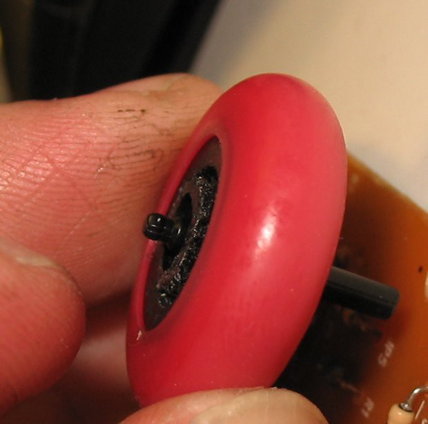
I drilled from the hollow side as long as the left part (with the hex profile) came appart (red rubber part removed for this step). Next step was to bring the SGI axle in shape:from this I cut away the left side and dremeled away the inner part:
Which left me with this 2 parts,
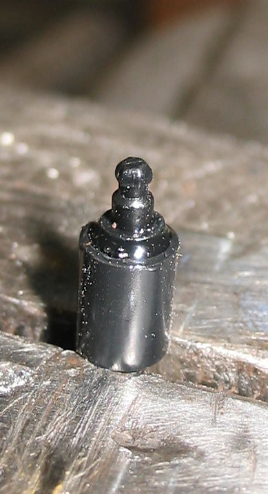
which I glued together (right part fits into left part):
This parts happen to fit perfect into the hollow part of the wheel (after the hollow shaft sticking out was removed)
-
case mod for optical PCB
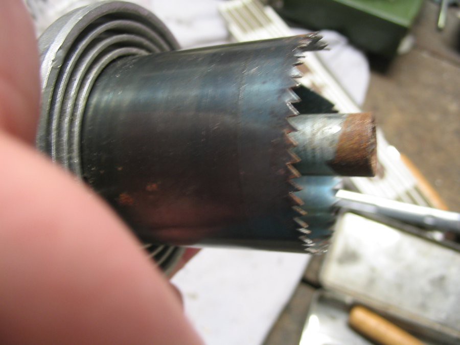
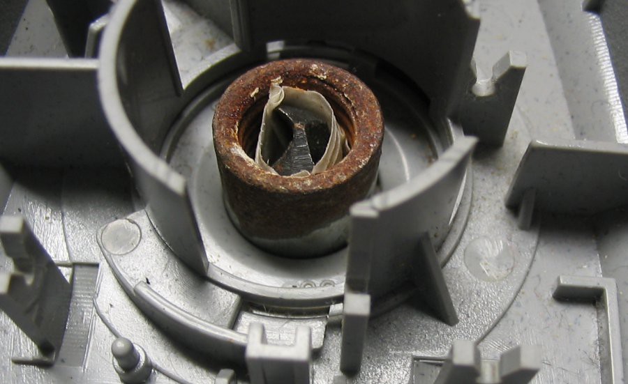
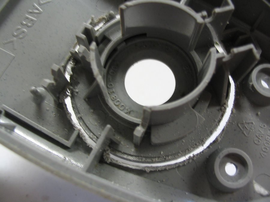
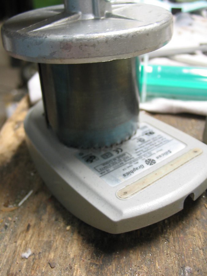
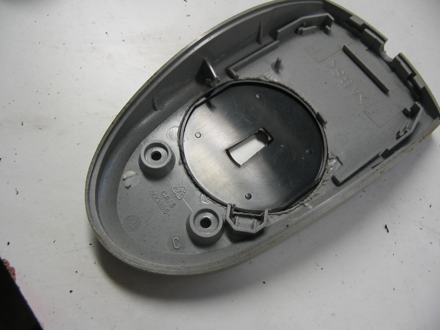
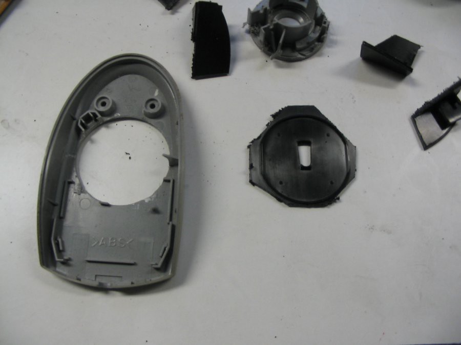
01/07/2015 at 13:10 • 0 commentsBecause the case part holding the lenses of the optical mouse had a nice circular design, I went for cutting a fitting hole into the bottom of the SGI mouse. The standard hole saw have a drill sticking out in front of the saw, which isn't helpfull if the part already has a bigger-than-the-drill hole, ehich is tha case for a ball type mouse. So I needed to fix that by modifing the saw, by putting a threaded sleeve arount the drill (some tape to cover the tolerances):
Then carefull drill until the bottom part is completly cut through:
The rest is work with pliers and file.
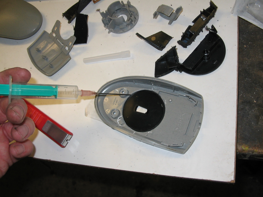
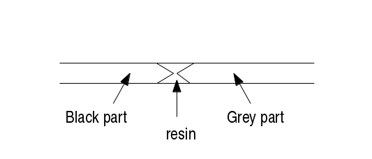
After everything was fitting, I made chamfers on top and bottom oft both parts, applied tape unterneath and glued it in with 10-min-Epoxy, using a syringe.
So even, if the resin won't stick good enought to the other plastic parts everything staies in place, because ot the form. It is only needed to applied the resin on one side, it will flow into the bottom gap fast enough before curing.
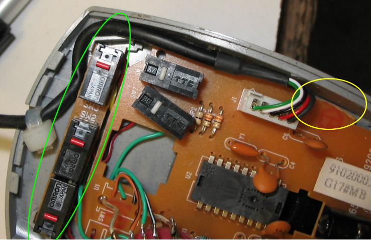
And here is a picture of the new board inside the old case (some adjustments to the board like in the yellow marking). And in front of that the piece of the old board carring the three orig buttons fitting in the holding notches of the case:
-
Disassamble and 3-button test
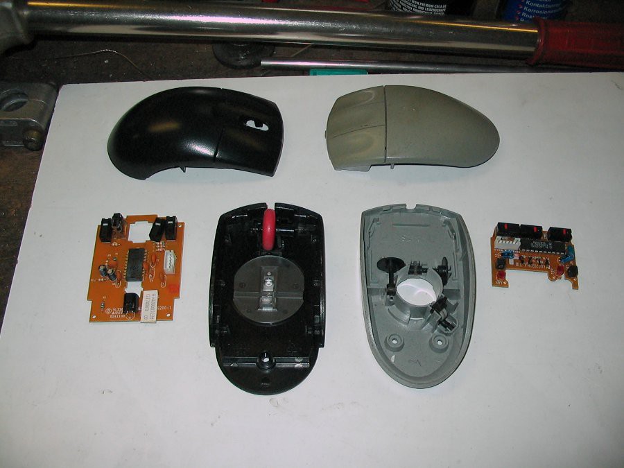
01/06/2015 at 14:00 • 0 commentsSo disassamble the two (cables not in picture):
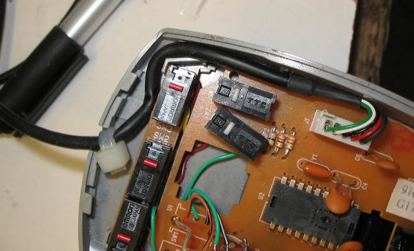
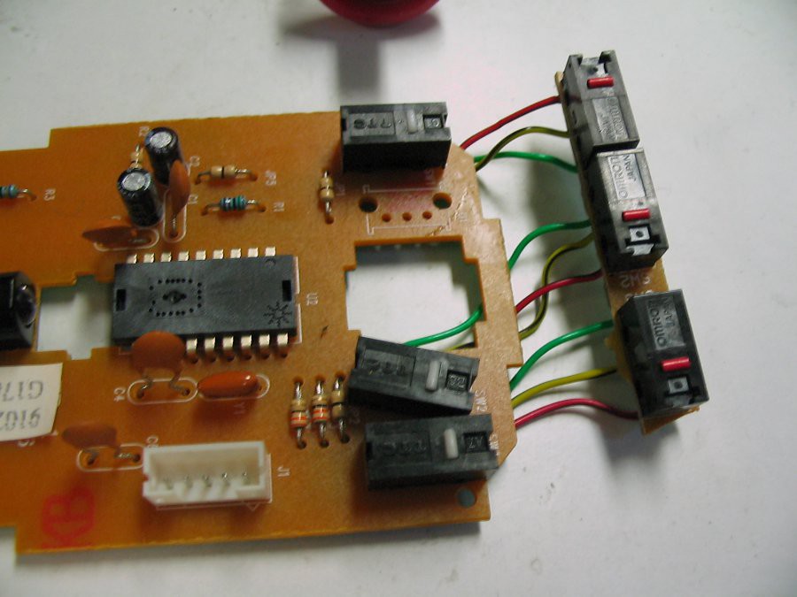
Quite differend design, but nevermind. So I want all internal parts from (black) USB mouse into the grey housing, the PCB part with the buttons should stay in place, therefore I used the original ones by cutting of the front part of that PCB and soldered them im parallel to the other buttons:
Yes, perhaps 2 wires each buttons would have done the trick also, but to be sure I wired them all. After that I did a short test and all buttons worked fine.
3-buttonmouse with seperate wheel
convertion of an old SGI ps/2-mouse to a 3 button USB mouse with a separat non-clickable-scrollwheel
 mclien
