12v Motor Driver
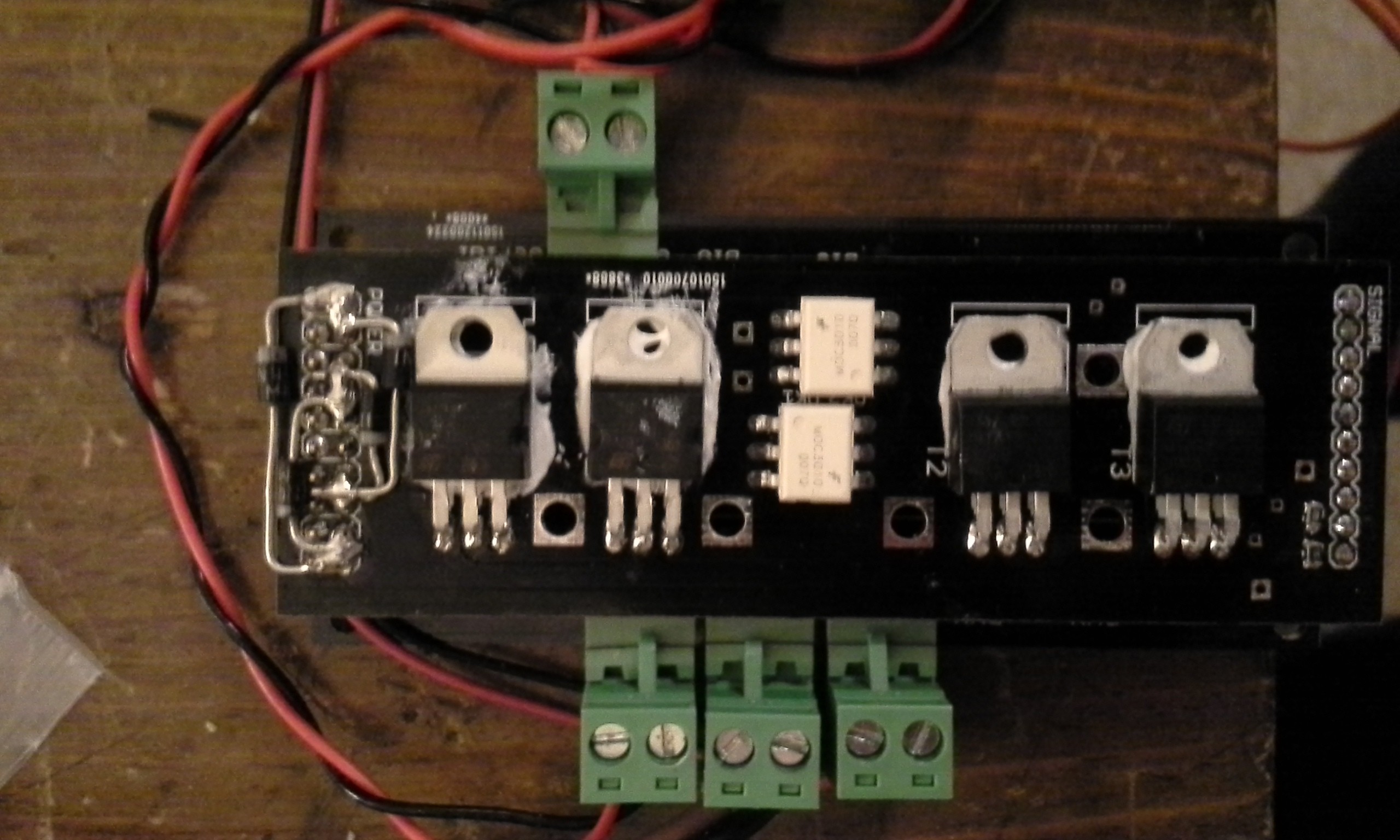
This board is to drive a 12v 5A motor using a microcontroller.
This board is to drive a 12v 5A motor using a microcontroller.
To make the experience fit your profile, pick a username and tell us what interests you.
We found and based on your interests.
I updated the BOM to reflect our use, currently we have to have six dedicated and three auxilary, making 9 total motor controllers coming in at just over $100 (not including shipping for the boards and parts). I think that this is pretty good because the closest equivalent circuit that I can think of is using four solid state relays per motor which would cost significantly more, and there would still be the same hurdles to overcome. Even with two solid state relays and the transistors it would have been more expensive.
This seems to have done the trick.
For the CRC8 I adapted the python code to the arduino/stellaris (same thing) but the link was interesting too.
Using the analog pins was a horrible idea. Got reliable communications just the same.
Yesterday, I thought that I had all of the kinks worked out. I had three boards working off of one arduino and everything seemed to be going well, but then the problems started again.
I am pretty sure that the problem that I am having is the timing for the serial communication. Sometimes the string will get messed up, and I had come up with several ways to make sure that I got a good data stream, but it was at the cost of update time. Ensuring that I got good data put considerable lag in the system. So for some applications the serial comms will work fine, but for this it won't. As of yesterday I thought I was beat, but there may be one more option.
The stellaris launchpad that is communicating with the arduino seems to be getting the data and getting it correctly every time, so what I am going to do is use it to pwm some pins on the stellaris launchpad and hook those pins to the analog pins on the arduino.
What I am hoping to accomplish is that the arduino only has to poll it's analog inputs and then produce a pwm on the appropriate pin. One consideration is that because the update will be faster and cleaner I will have to create a longer delay before changing the motor speed so that I don't keep popping the transistors.
More to follow...
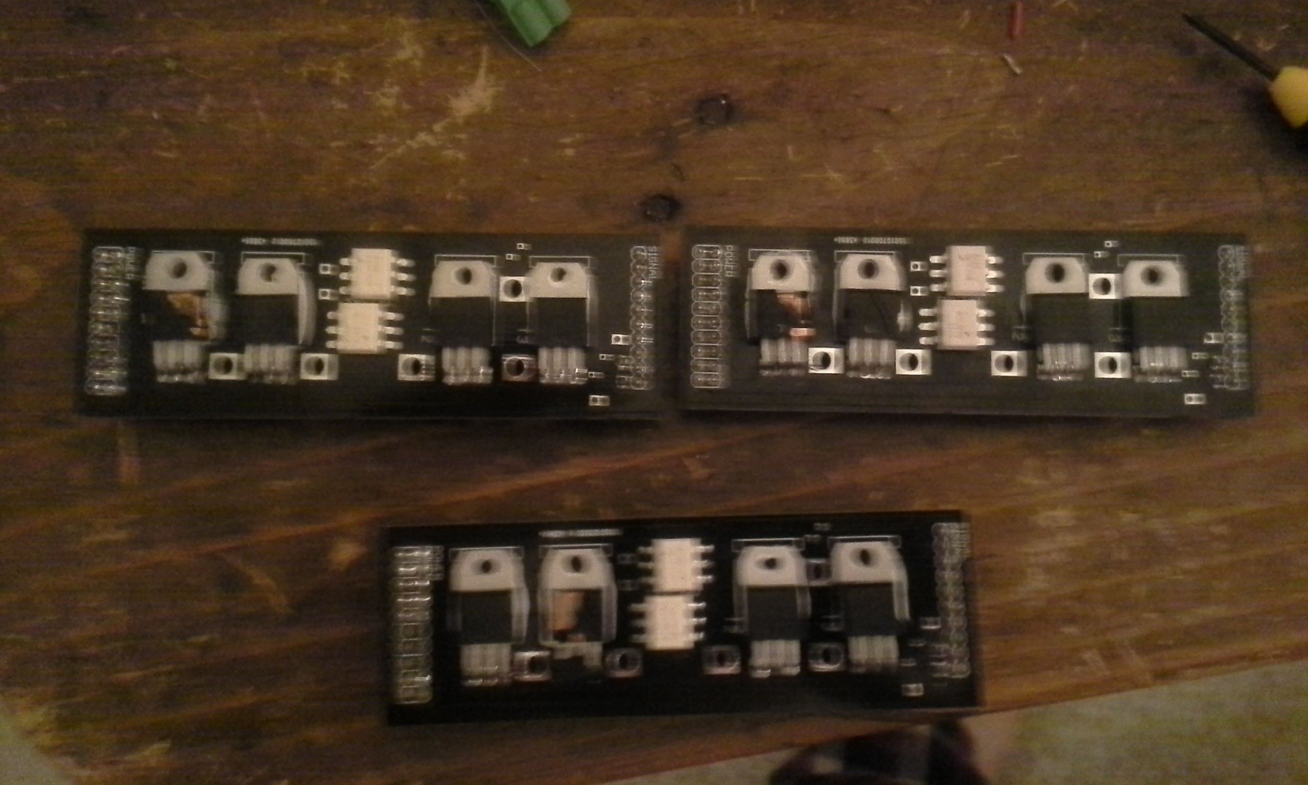
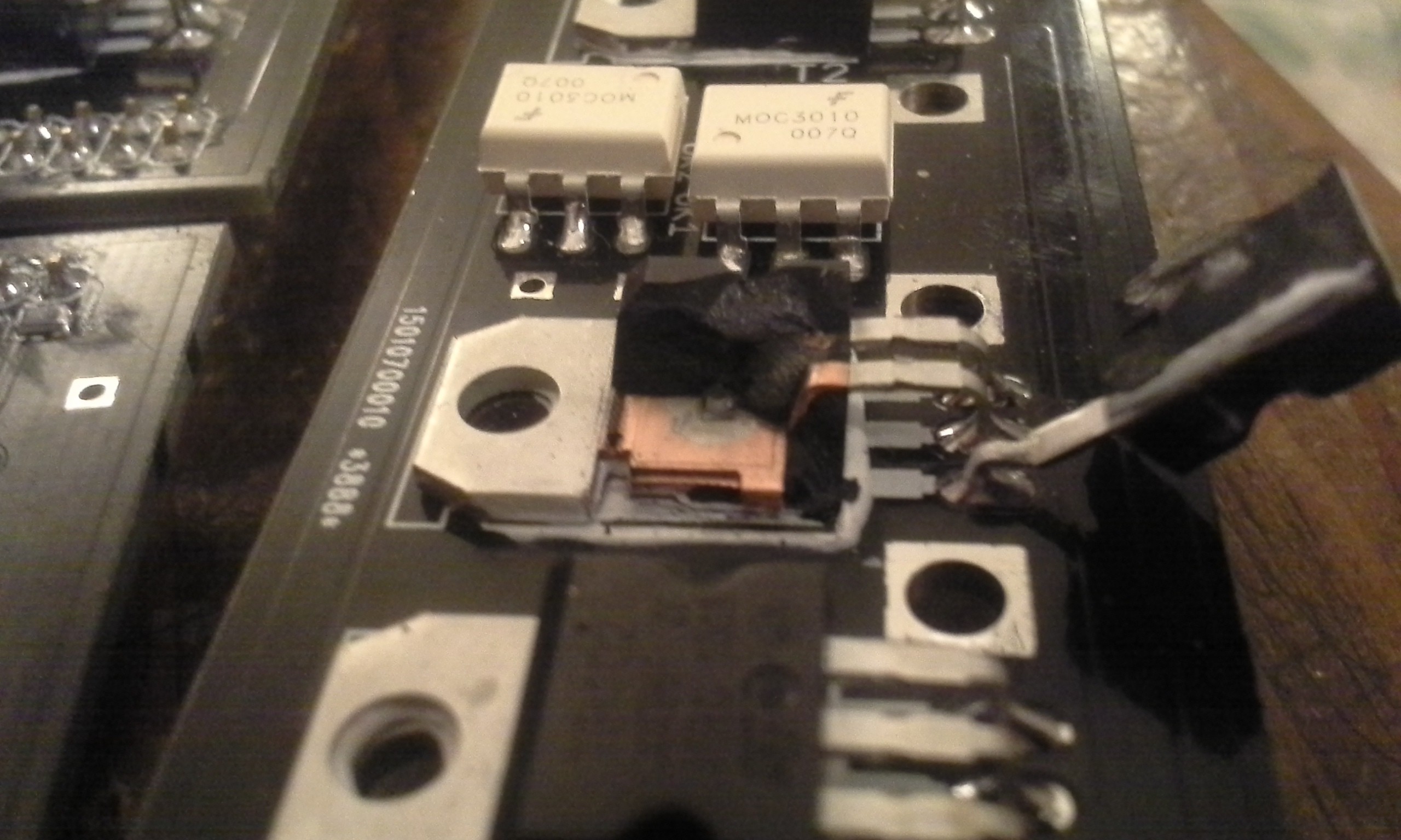
I blew up 5 tip102's and 3 arduino's trying to figure out where I went wrong. The problem was that I did not have a delay before changing the rate of pwn to the transistor. The problem is fixed and 90ms was as low as I dared to go. Unless you want to remove the package of a transistor very quickly I would not recommend using the code on github. I will update it in the next couple of days as it now seems to be working.
I used the autorouter tool in eaglecad for the control board, and for this it seemed to work ok. I had tried it on a more complicated board and there were horrible results ( in my uneducated opinion). I think this is the extent of the autorouter capabilities.
I tied the power from the lm317 to vcc instead of raw. I corrected it by clipping the pin off of the header for the arduino and jumping a wire from the vcc hole to the raw pin.
I also corrected the drawing, so there are no versions of the drawing with the mistake.
It may also be advantageous to add a jumper to the board for addressing so that only one program is needed for the arduino's.
It is also good to know that the pins on the stellaris launchpad are tolerant of ~8v.
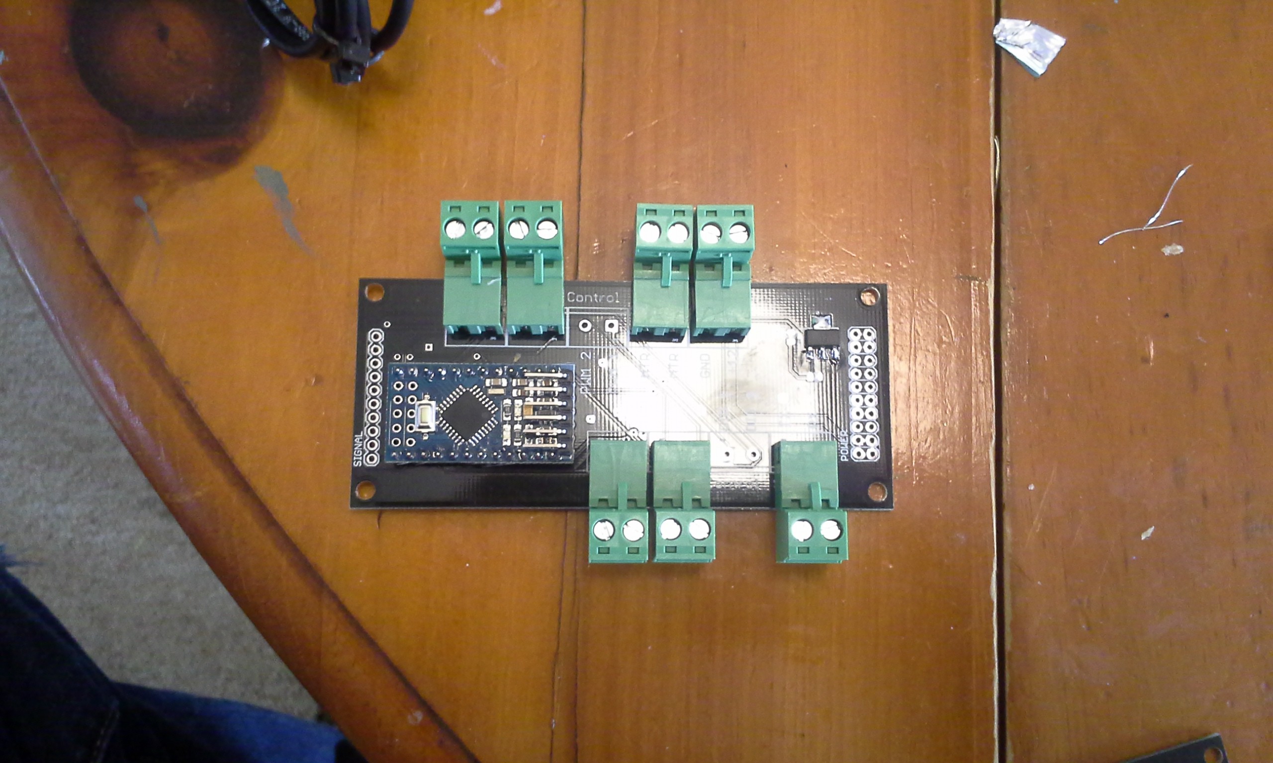
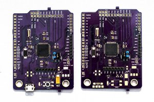
Control boards arrived.
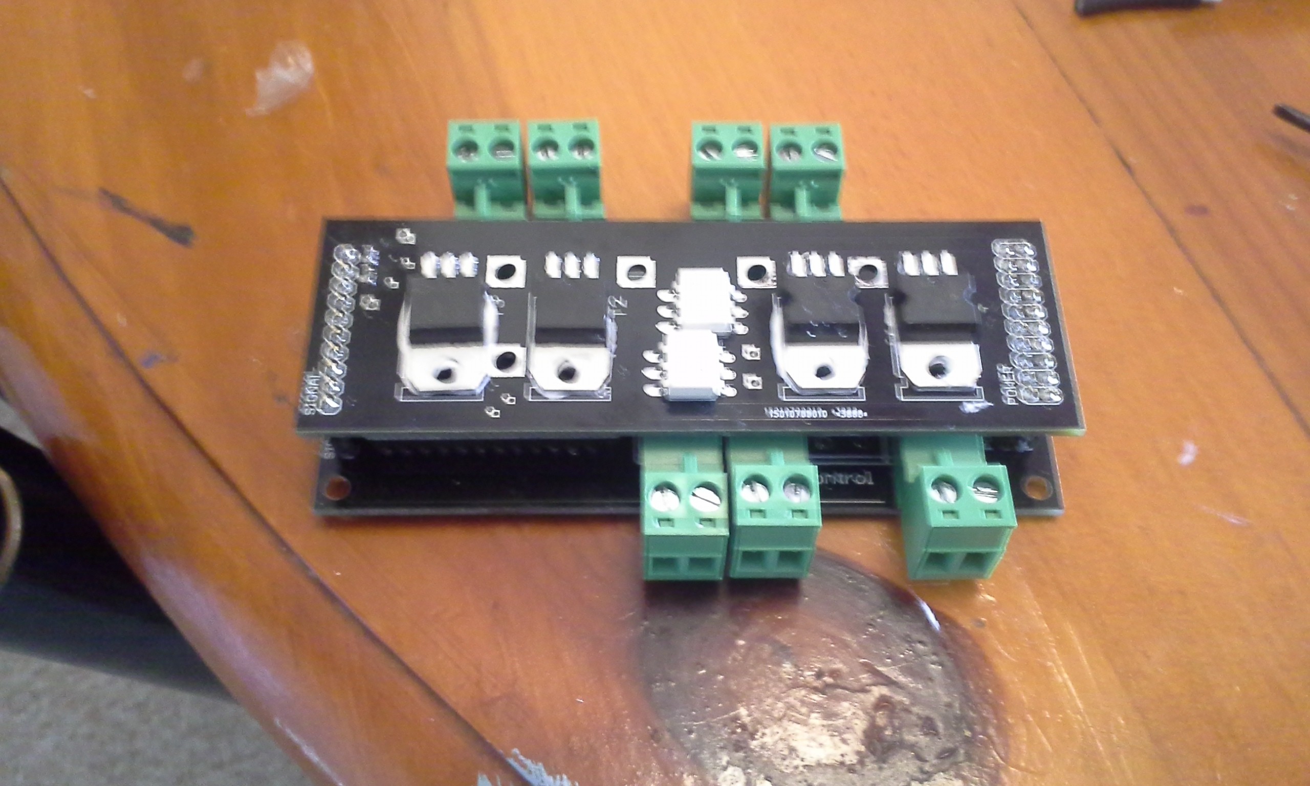
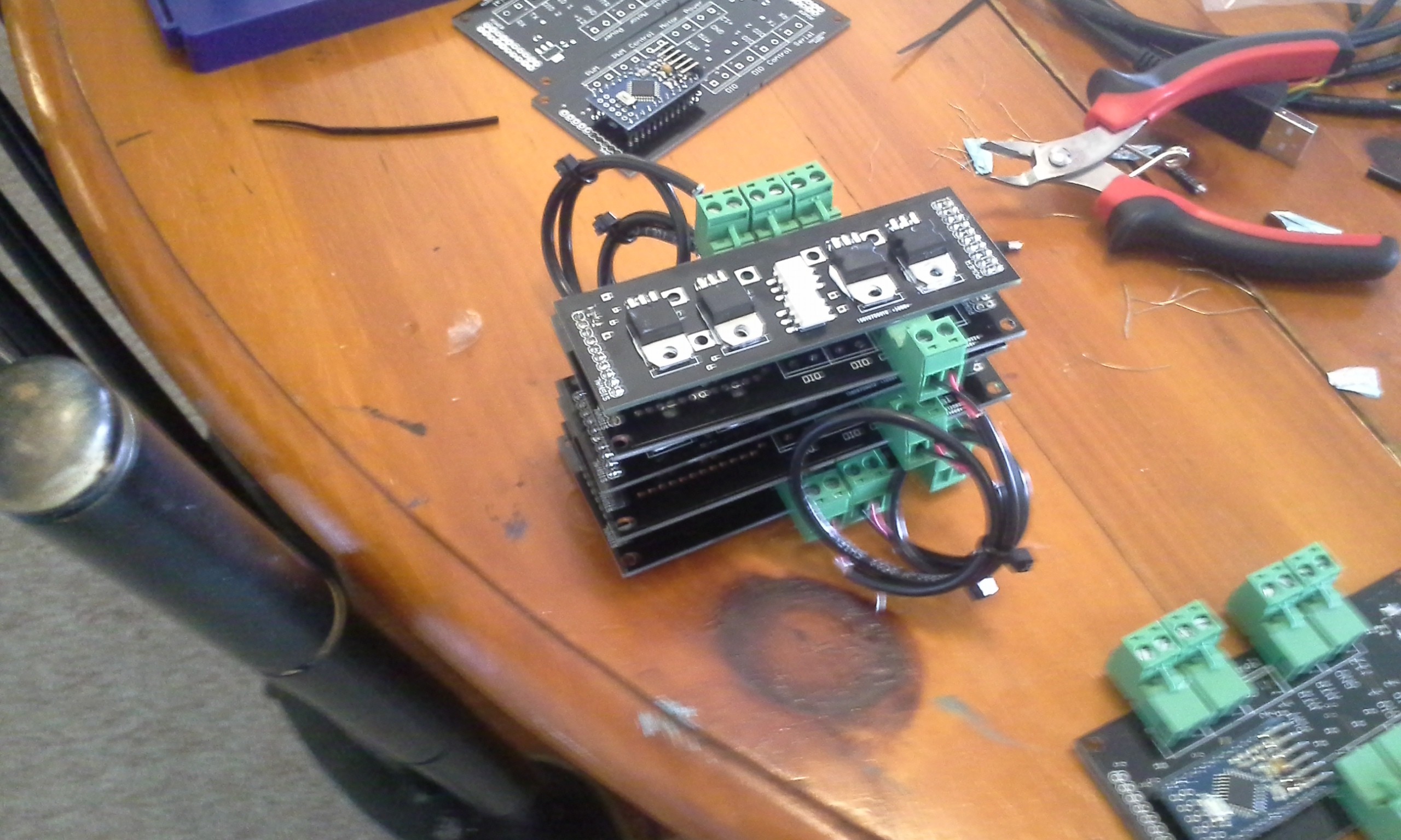
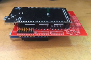
Stack of three. The control boards are populated with an arduino, but the 'slave' boards are not.
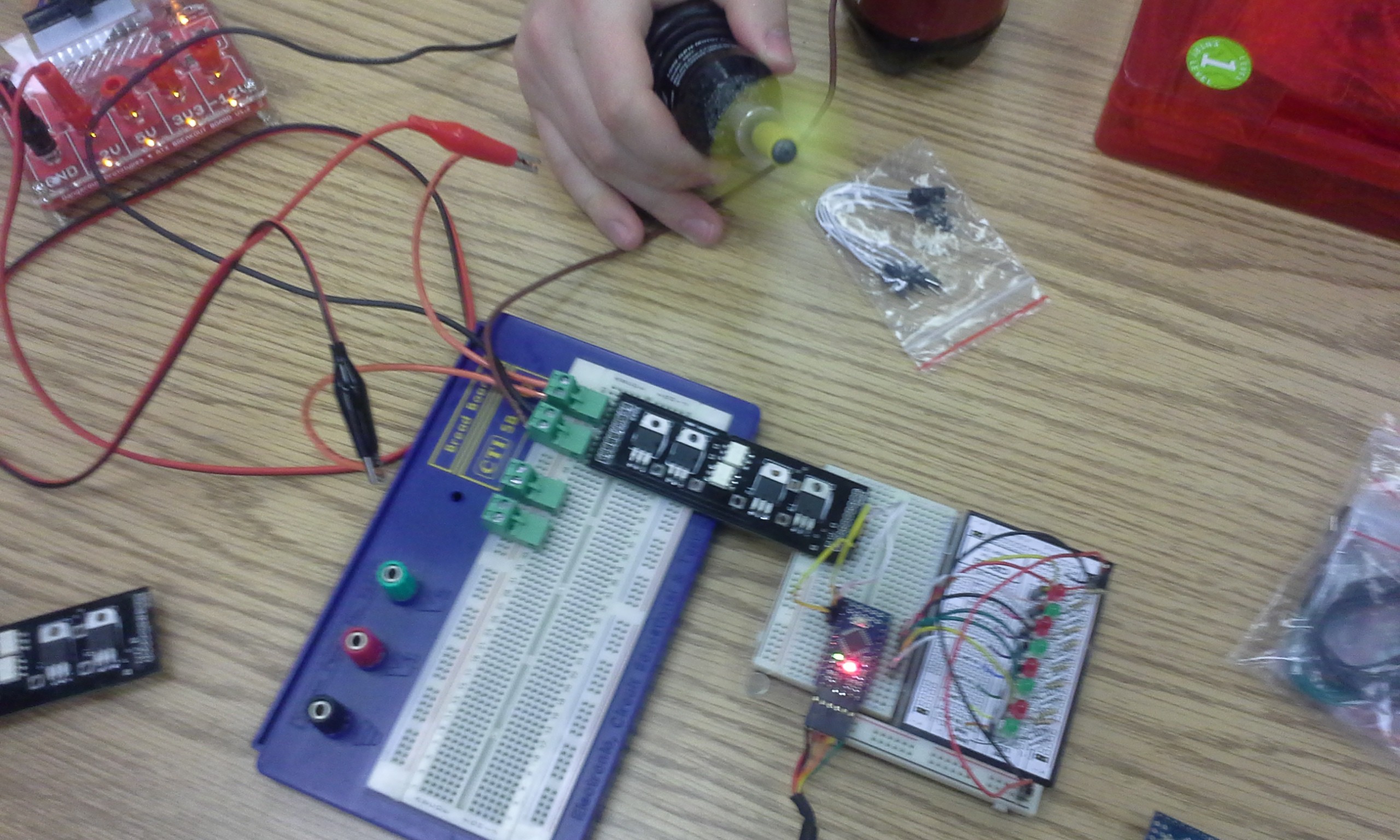
It worked better than I thought, without the heatsink. Building and running them without until I find a reason not to.
Create an account to leave a comment. Already have an account? Log In.
The TIP102 and TIP120 are both darlington transistors. Here's what i meant by 'taking avantage of the opto couples isolation' -

The resistors that go from the bases to the power rails are there to make sure the transistor turns completely off quickly. This is helps overcome the problem created with the base to emitter capacitance (Cbe) of bipolar transistors. This reduces the time to turn off and therefore the bandgap. The complementary pair to TIP102 is TIP106. The resistors are determined by Vcc, I (max), and hfe (min) of the transistors. The same can be done with FET's but complementary FET's are harder to find and more expensive. FET's are the solution for very high currents. A similar thing can be done with TRIAC's. But TRIAC's conduct in both directions and that is unnecessary for a H Bridge.
Thanks for posting that! I will breadboard it as soon as I get a chance, and make a cad drawing for later use. It looks like it would solve the problem I am having with the motor revving up when I bring the power to ground to shut the triac off, and I would be able to use two less pins.
PS: I have drawn the circuit with opto-triac drivers insted of opto-couples. Although opto-triac drivers would work, I did intend to have normal opto-couples in the diagram. I probably slipped up because I just finished a circuit baord with MOC3021 opto-triac drivers and BT137's.
I wondered about it, but wasn't worried because I have a bunch of moc3010's from this build and would have just tried them anyway.
I don't see any fly-back diodes on the transistors or Triacs. Since the motor is an inductive load it's easy to get 100s of volts when the transistors turn off. This can easily push the transistor into avalanche breakdown, or trigger the triac.
I have a few power diodes. That will be the first thing I try. Thanks!
Figure & here
http://www.bristolwatch.com/ele/h_bridge.htm has a opto-coupled (MOS)FET H bridge. This is the common way to do this. There is more usfull info on this site as well.
I can't seem to find a pic to send for a TRIAC H bridge, probably because it is not the common way to do it. I use TRIAC's this way but in a half bridge where you don't need to worry about band gap.
Originally I had breadborded a triac H-bridge, but it didn't work. I didn't spend any time playing with it, but I think that the problem was that I needed to add some diodes. None the less, the transistor is the weak point right now. I hope to find a solution to that, and later I will revisit the triac H-bridge.
I can see the current input traces for the TIP120's
If you want isolation then you have a number of options. I wouldn't use TIP120's with an opto-couple because they will be very slow to turn off and even more so if you add more gain with an opto-couple (current transfer ratio). The TIP120 is a darlington transistor with a DC current gain (hFE) of 1000 that is made for linear regulation so it is slow. Transistors have a property that acts like a capacitor between base and emitter (cBE). In a darlington this unwanted property is amplified by the second transistor making it slow to respond but that is fine with a linear circuit. It is not good for PWM or non-linear drive (digital).
You could use complimentary FET's or just stick with four BT136's. BT136 have a low gate drive requirement so most opto-couples will be fine just check the math from the datasheet. I often use 4N35's because they're common.
If you take advantage of the fact that the opto-couples isolate then you would only need two opto-couples for the four BT136's or complementary FET's in a H bridge and still be able to band gap.
I will google to see if I can find a link to a schematic of a H bridge that has 'off bias' on the control gates.
Also, I know the drawing says TIP120, but I am using a TIP102. I was too lazy to recreate the part in the library as they are schematically equivalent. Thanks for the info though. If you have any insight into working with the TIP102 I am all ears, or if you know of a replacement part that can handle the abuse I am dishing out that would be great.
I may also just be creating a dead short because the transistor is not turning the triac off and when I fire the other triac... pop. I may put some pnp transistors on the power side. Cut it off the same time I remove the gate from the triac and then drive it low. Don't know if it will work or if I will just be making my headache bigger, but it will be fun.
This reminds me of my favorite fortune cookie...
Good judgment comes from experience, experience comes from bad judgment.
Also see -
http://www.picbasic.co.uk/forum/showthread.php?t=10564
If you want to drive several motors.
Thanks for the link. That is interesting, but for this application I think that what I have here is the way to go for right now. There is a strong possibility that some of the parts may get wet, and I am hoping to limit failure unless something catastrophic happens. I also don't have much experience with pic, but from what I have done it takes a lot longer to program and to change the program and this is a situation where I want to be able to make changes as rapidly as possible and be able to develop a working baseline that is easy to step into and figure out what is going on for someone that is totally new to the project. I hope that future revisions are cheaper and more efficient, but I will leave these changes to others.
With a BT137 then you can do away with the optocouples unless you specifically need the isolation. You can drive it from the uC with just a series resistor.
And ahh yes - band gap - you need time for the TRAC to turn off and for the back EMF from the inductive motor to subside - or pop lol.
Some reverse biased diodes will help kill the back EMF faster by dumping it to the power rails otherwise it can keep ringing for some time. If you have a scope available then try the diodes and you will see how much difference it makes.
The other triac's would definitely be worth testing, I only have a high level understanding of the part and don't have much experience with different tirac's, but isolation may be the way to go. I think that it would have been a good idea to isolate the transistors as well. Maybe 4 of these would have been a good idea ( http://www.mouser.com/ProductDetail/Vishay-Semiconductors/K817P6/?qs=sGAEpiMZZMteimceiIVCB6uJB2r5Coumb%252b%2fZymX8n%252bU%3d ).
But I also considered this a part that would fail and I wanted to keep the number of components to a minimum so that it would be easy to troubleshoot and rework.
Become a member to follow this project and never miss any updates
 nerd.king
Nice work, keep it up