fl@C@
fl@C@-
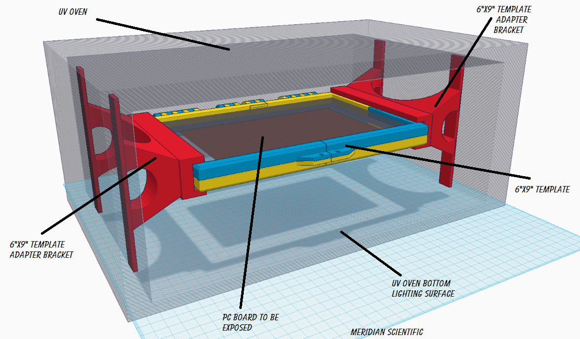
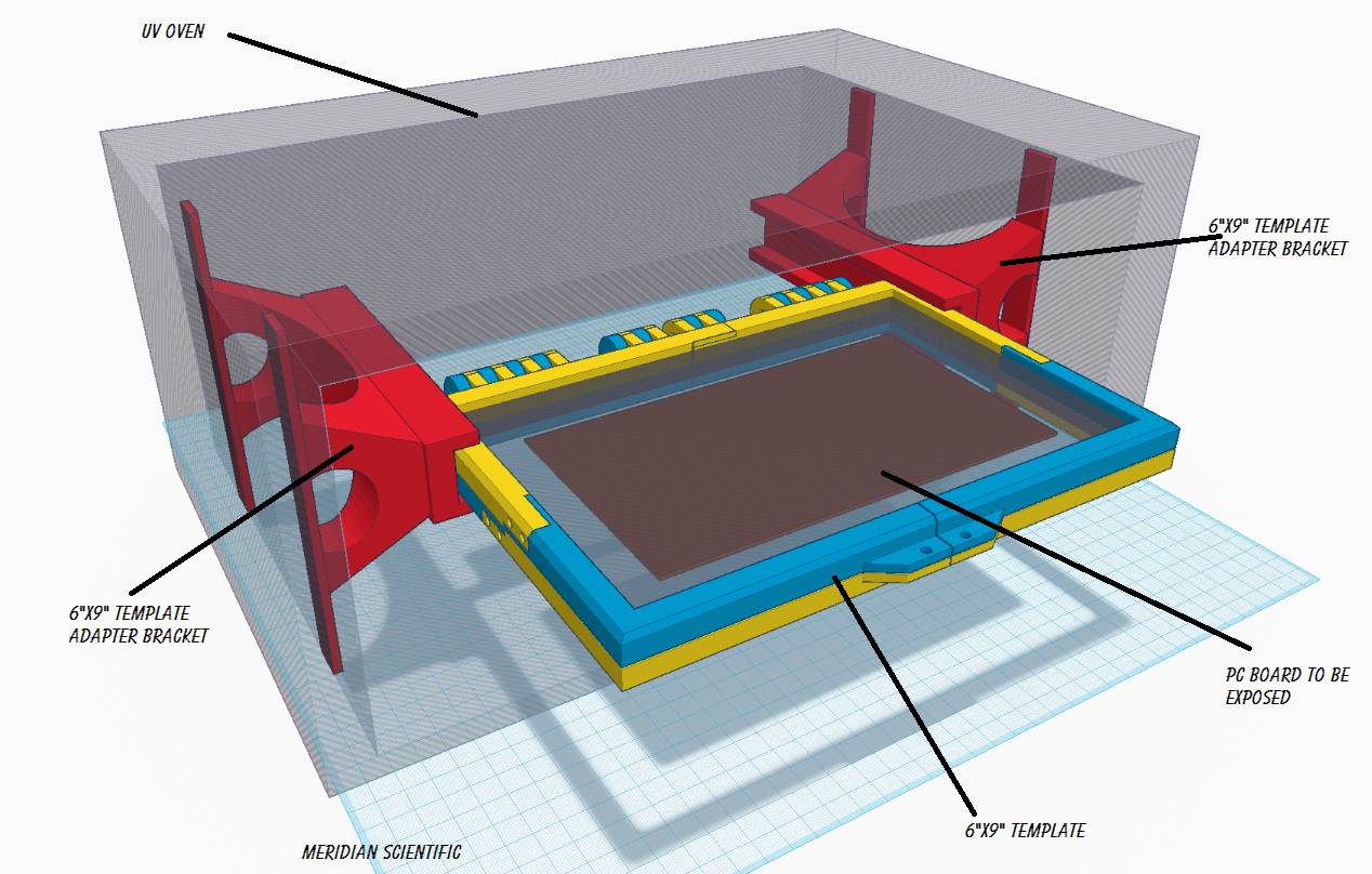
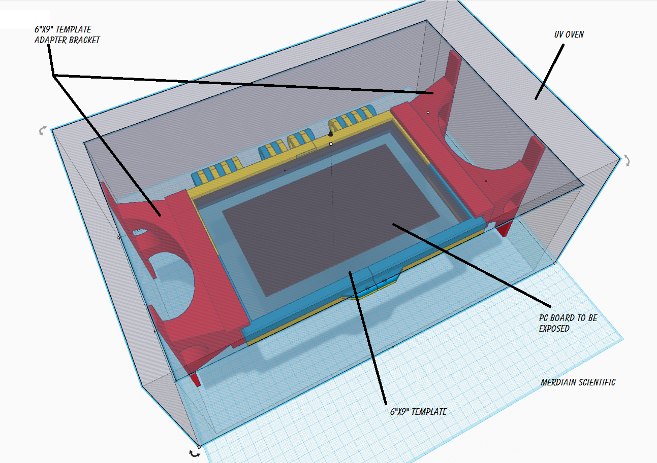
Almost ready to go with the templates!
04/25/2015 at 05:55 • 0 commentsHere's some renderings of the brackets to hold the templates from the Tonerless PCB Templates for UV Exposure project...!!
I think it's coming along great...
![]()
![]()
![]()
![]()
-
Done..
04/13/2015 at 03:53 • 0 commentsSo, I'll post some schematics and the source code asap... It's been done for a few weeks now, but I've been so busy on the other projects I haven't had time to document this one yet... Keep an eye out!
-
Almost done..
03/18/2015 at 20:01 • 0 commentsOk.. So, I'm almost done with this thing... Sorry if I haven't kept as detailed a log of the build as I did with ramanPi... but there really aren't enough hours...
When it is done fully.. I will post instructions, pictures, schematics, and everything...
This project has been more of a means to an end for me than something I really wanted to polish off and make super nice... I didn't have the time to spend on it to do that.. But it is functional and gets the job done..and leaves a lot of room for improvement..which I will probably do in the future.......
I ended up skipping the touch screen because the US Post Office cannot seem to do their job to save a squirrel... I swear half of my eBay purchases are sold off the back of a truck somewhere across the street from the post office...
Anyway, I settled on a pretty cool solution anyway... and I'll post some shots of it when I get them uploaded... It's an 8 digit/8 key 7 segment display board (from eBay of course)... Works great.. since I settled on using an arduino here.................there actually was a pretty good library for it... kinda fun to play with actually...
The interface is a menu with a clock, countdown timer, duration settings, brightness for all four banks individually, start delay, alarm setting, auto shutoff when done..... will have fan control, and possibly some wifi or ethernet stuff since I'm lazy and would like to monitor it from my desk without walking across my lab... ;)
I'll warn too that my source code is sloppy since I didn't spend the time to clean it up or anything.. but it works..so there ya go...
If there's more interest in this project, I might make more effort and get everything cleaned up and everything....
Here's some pictures....
![]()
![]()
![]()
![]()
-
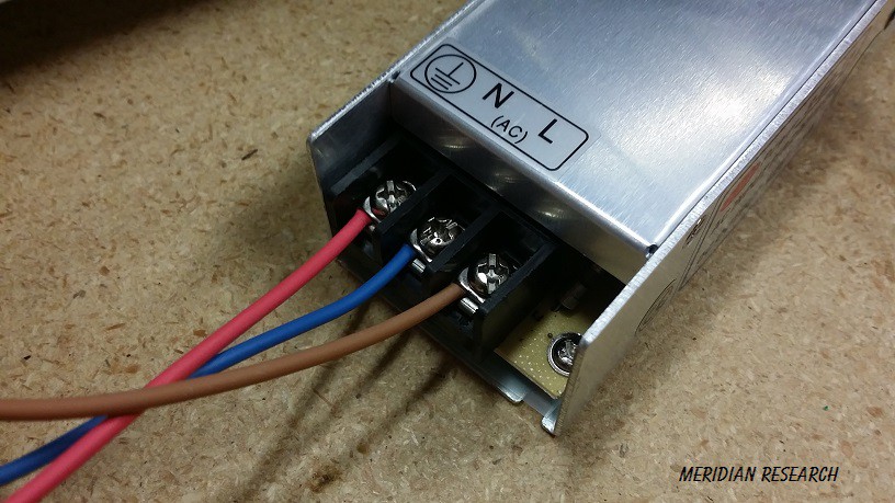
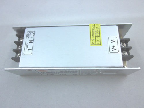
Power supply
03/12/2015 at 12:00 • 0 commentsI decided to go with a 12v 5amp supply... From my tests, the most the entire system with 300 LEDs all on at one, it draws about 2.5amps.. This power supply from eBay (of course) was only $10... I don't really care for wall warts or inline power supplies so this should do nicely and allow for future expansion if I need...
![]()
-
Progress
03/12/2015 at 09:52 • 0 commentsWell, I have all the LED strips cut into 12" lengths... and stuck 5mm apart on top and bottom of the inside... They're offset on the X to provide a fuller coverage since the LEDs are spaced oddly on the strips..
The strips are divided into four banks... and interleaved two on top and two on bottom.. These are connected to the four channels on the mosfet board and controlled by the arduino... I just typed that... <sigh>.. Anyway, the microcontroller will be connected to the touch screen TFT when it gets here from China.....I ordered it march 4th... so it should be here before June.. :) There's really not much to it other than the power supply... I'll be feeding the LEDs with a 12v 5amp power supply.. and the micro will probably be run from a regulator...I tend to like to LM2825-5.0 but, I don't imagine a lot of people share that...so I'll probably use something more mainstream.. I'll also probably be designing a board for this which will include the micro and everything... Keep watching... :D
-
Some pics
03/09/2015 at 13:00 • 0 commentsSo, here are some pictures of where it stands at the moment.....
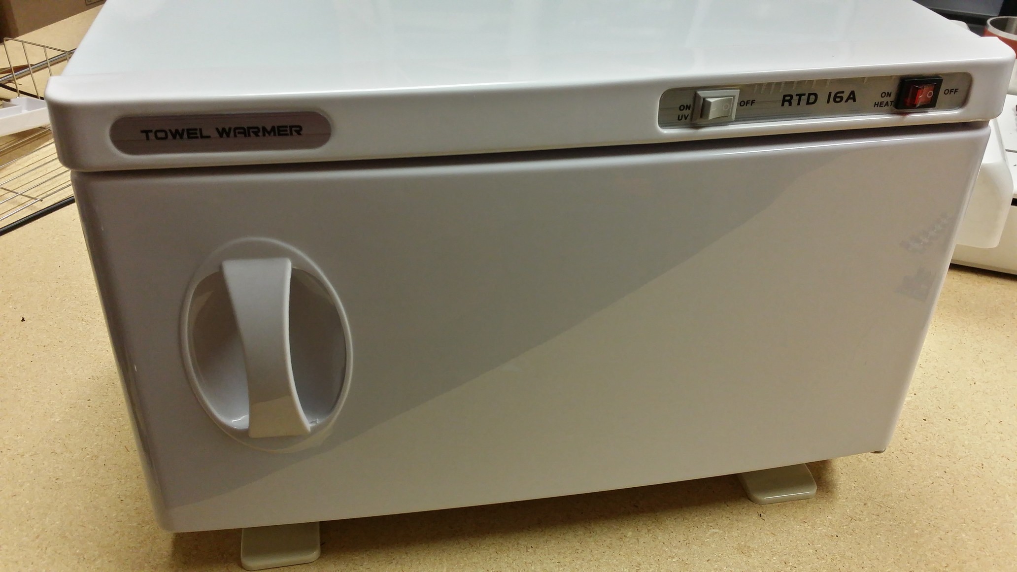
New..... From the front...
![]()
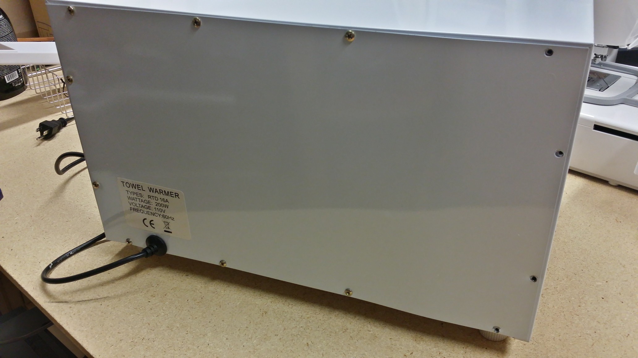
New from the back...
![]()
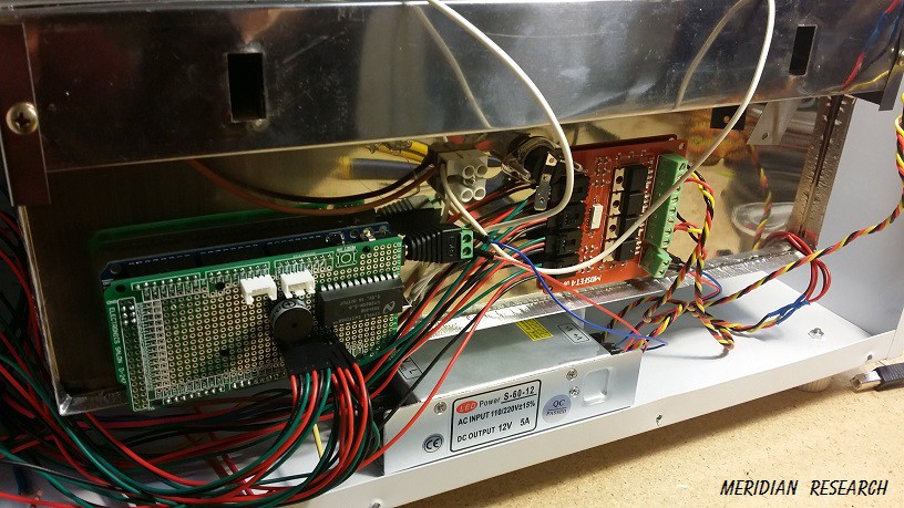
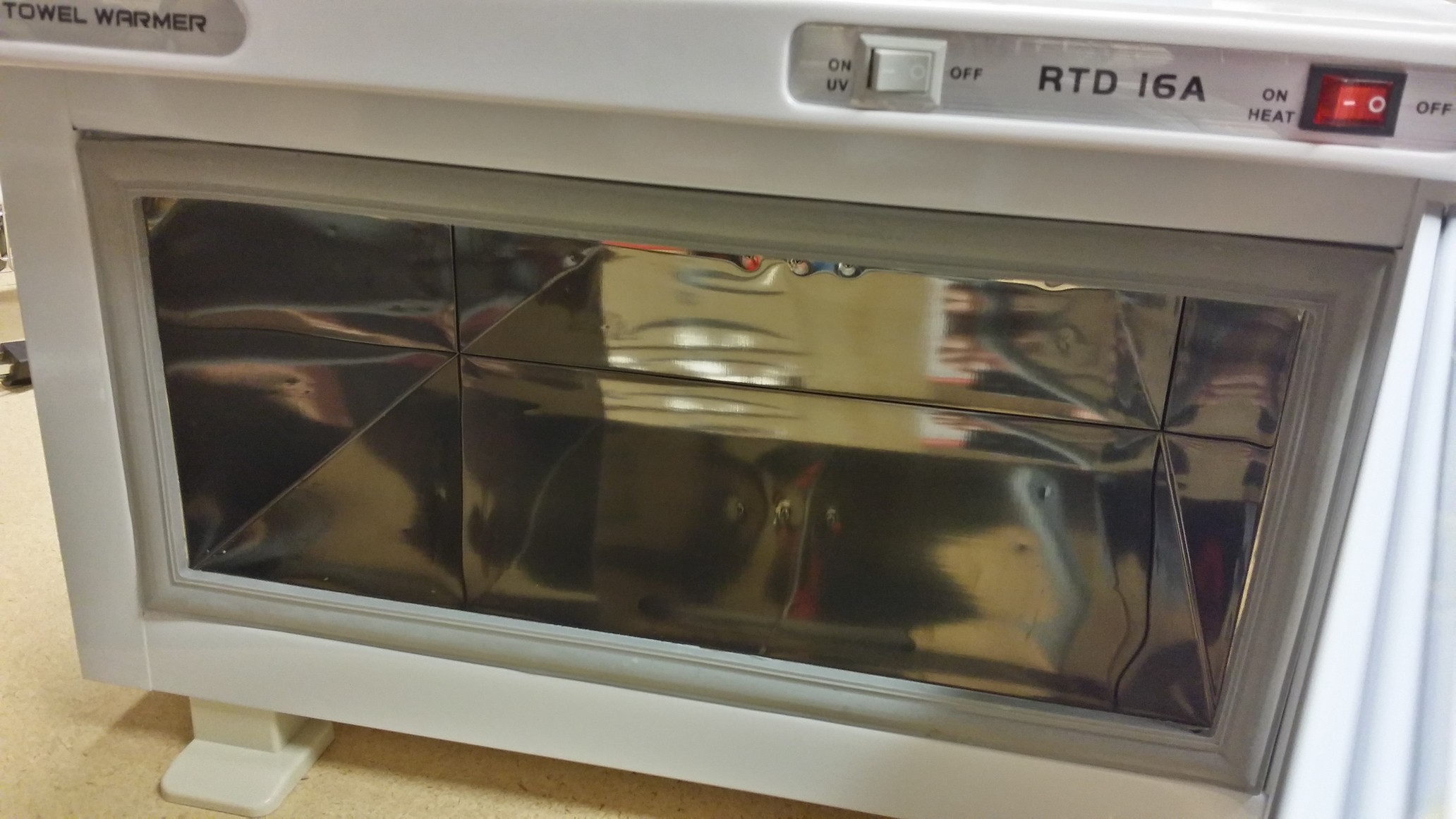
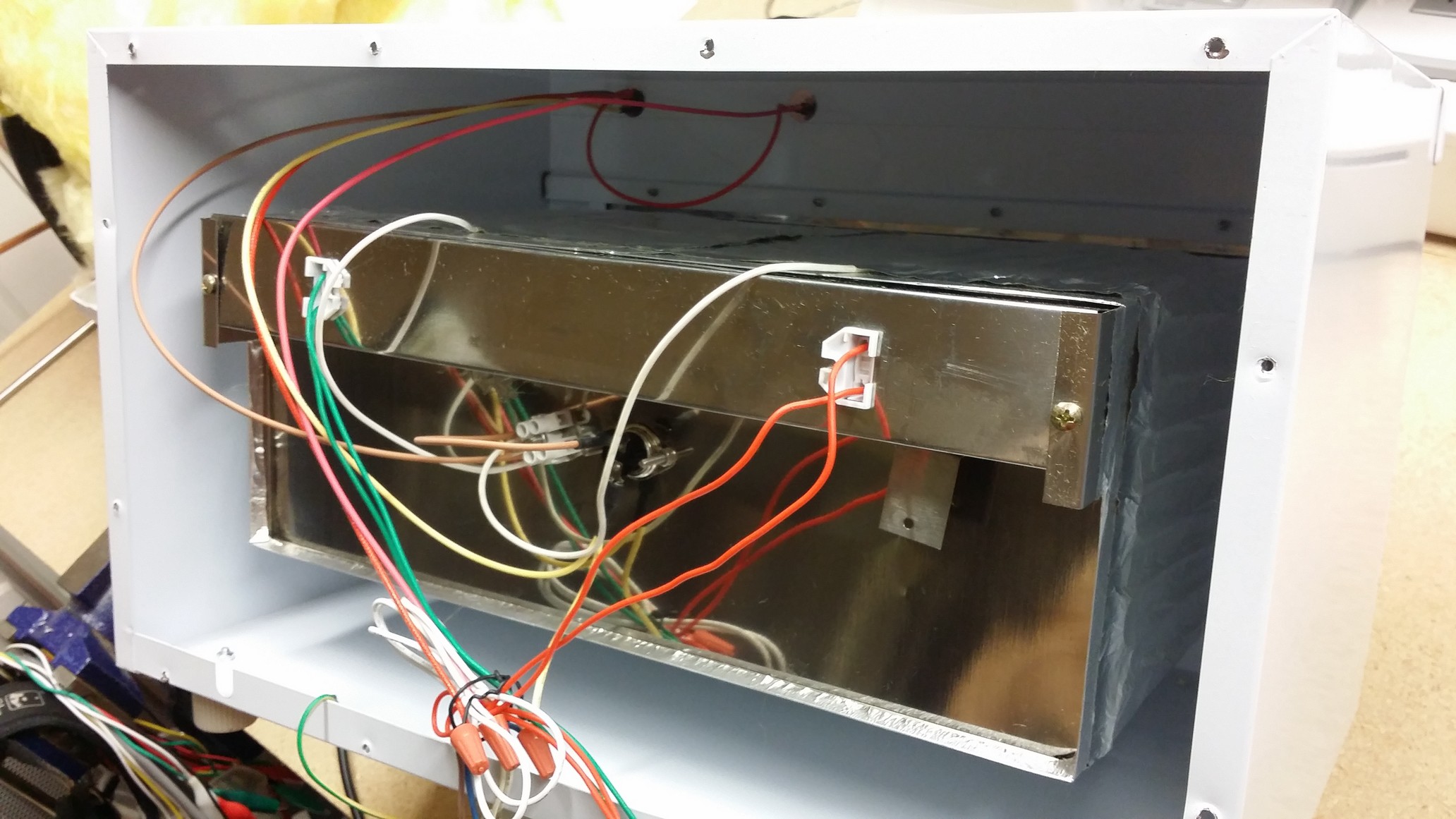
New from the inside....
![]()
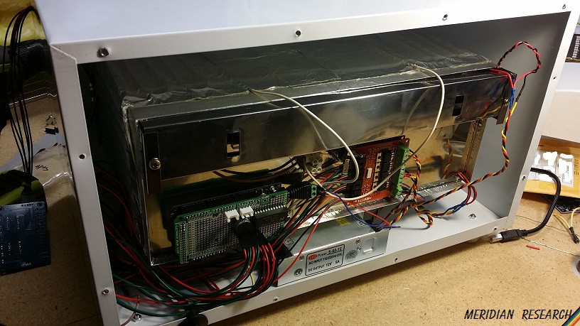
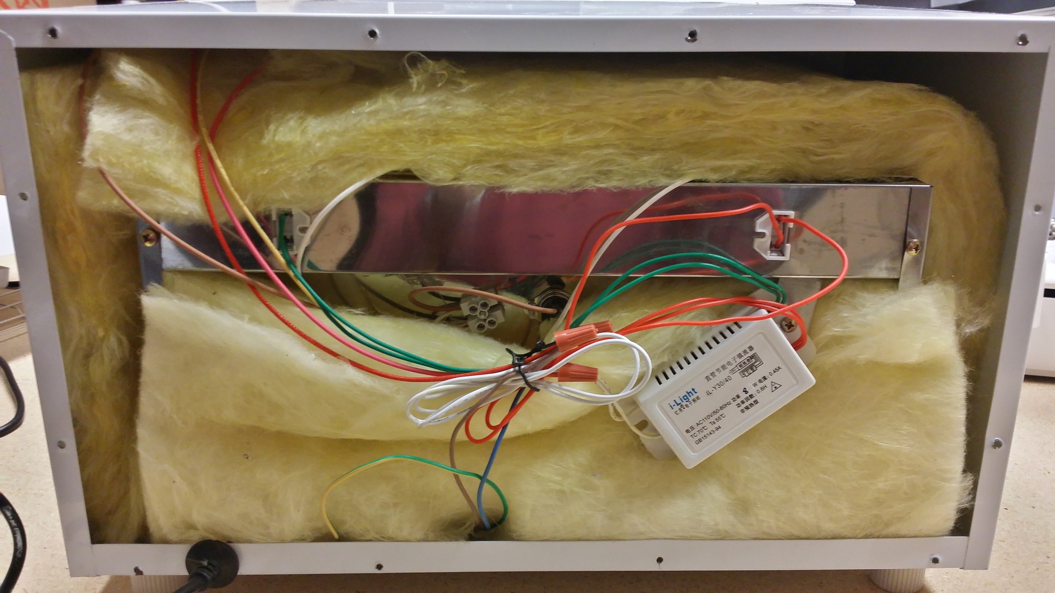
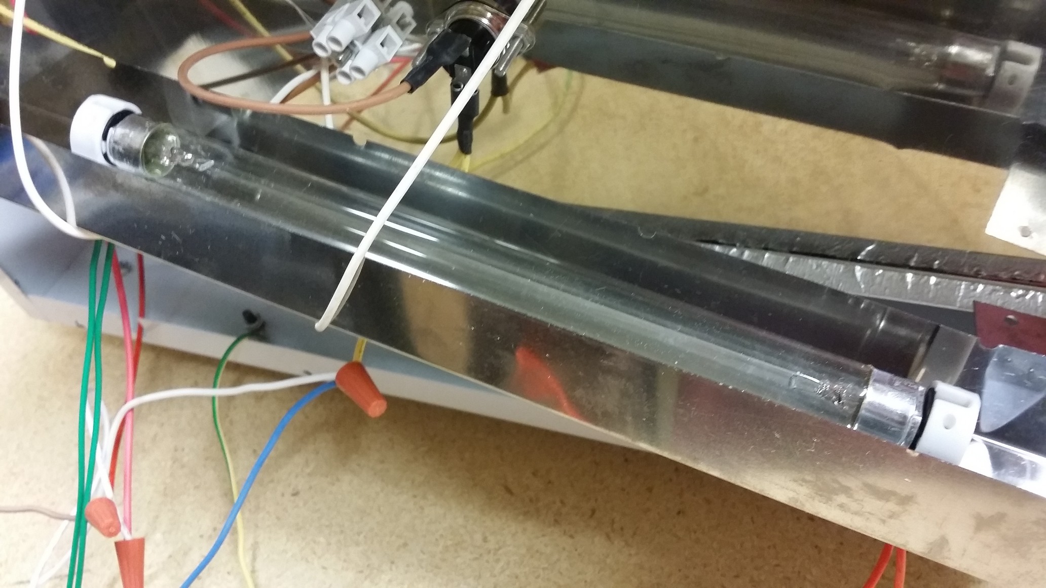
The back removed.... what a mess...
![]()
The UV fluorescent tube... I was originally planning on using multiple tubes, but decided against it since they are so clumsy....hard to work with, control, replace, and so on... LEDs are much more appealing...
![]()
The insulation after being removed... Yuck..
![]()
The wiring mess that just gets ripped out... I don't see a need for the heater.....
![]()
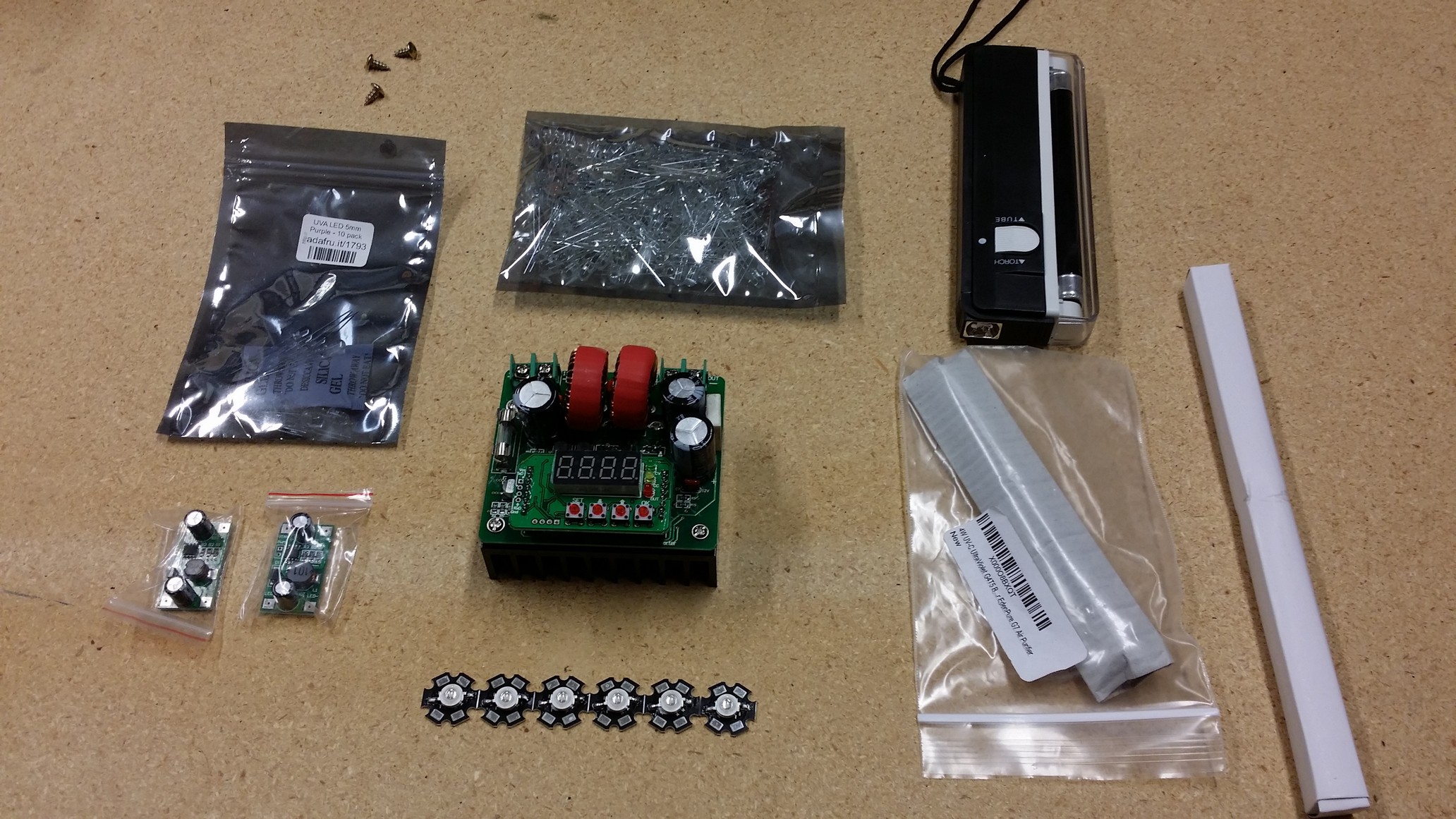
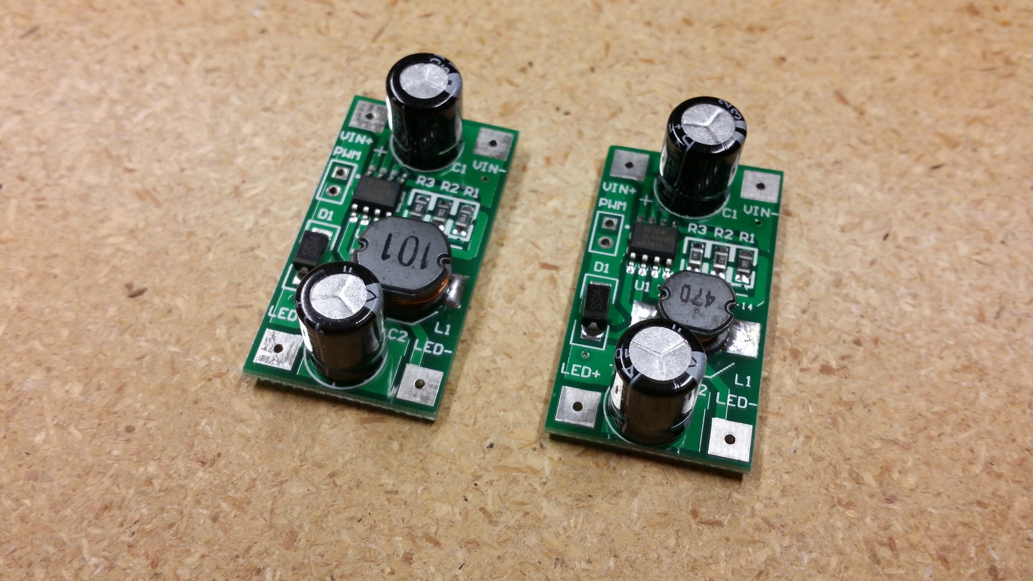
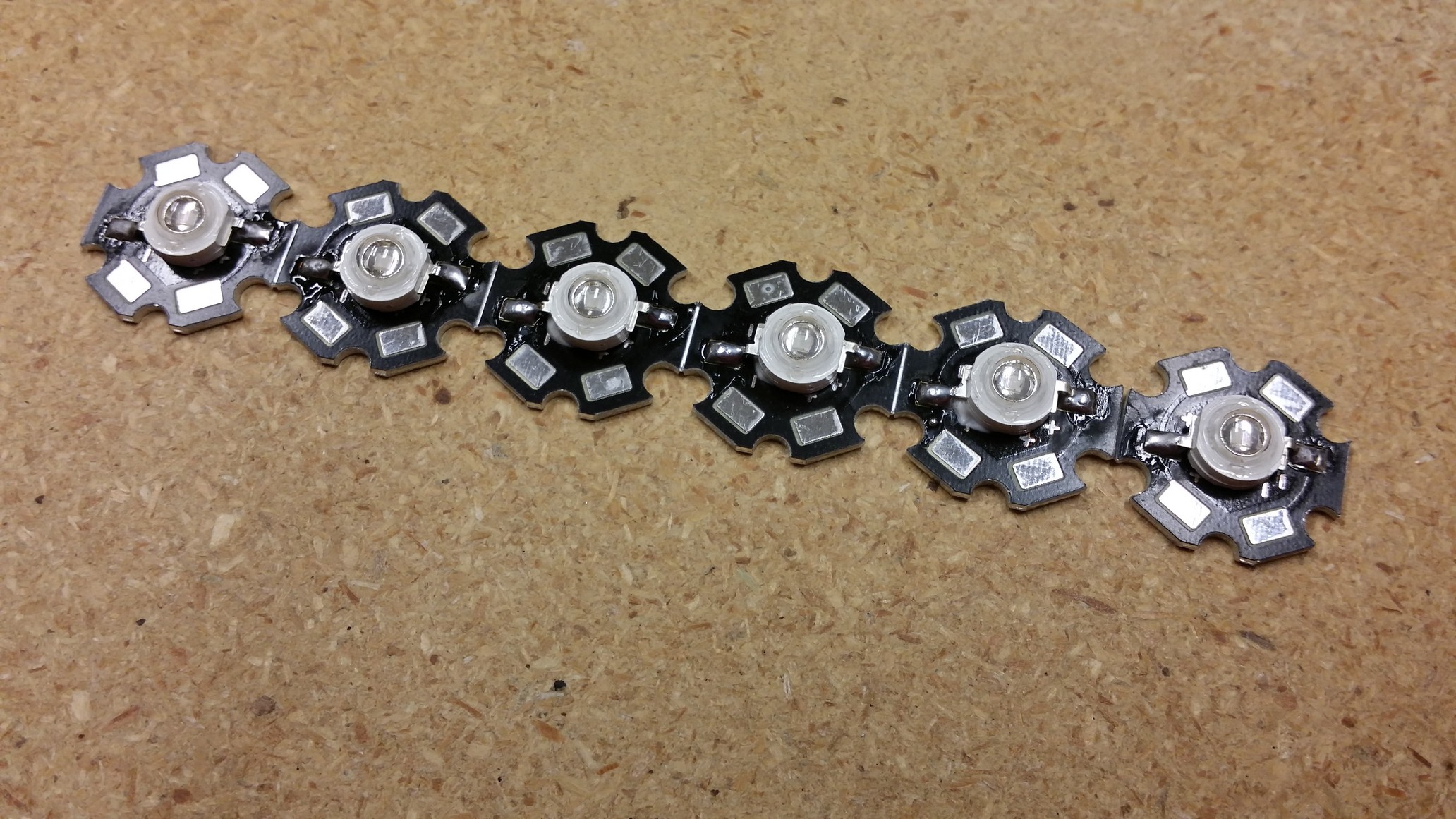
The first round of parts I planned on using to control the 3watt leds... (and note a bag of 200 5mm uv leds as well as the uv tubes)
![]()
![]()
![]()
![]()
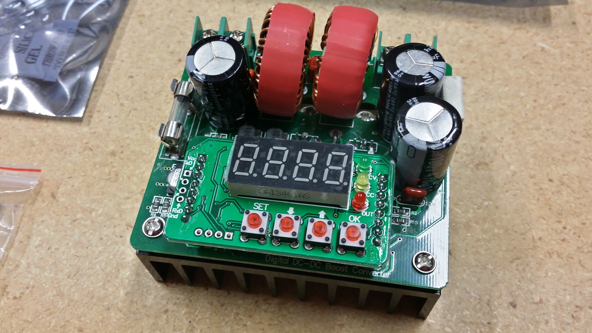
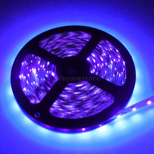
So, after the frustration with that boost converter and the 3watt leds... Here's what I'm waiting on from china at the moment...
Two reels of 300ea UV LED tape... $27.80 for 600 LEDs... 12volt 395nm 16.4ft each...
![]()
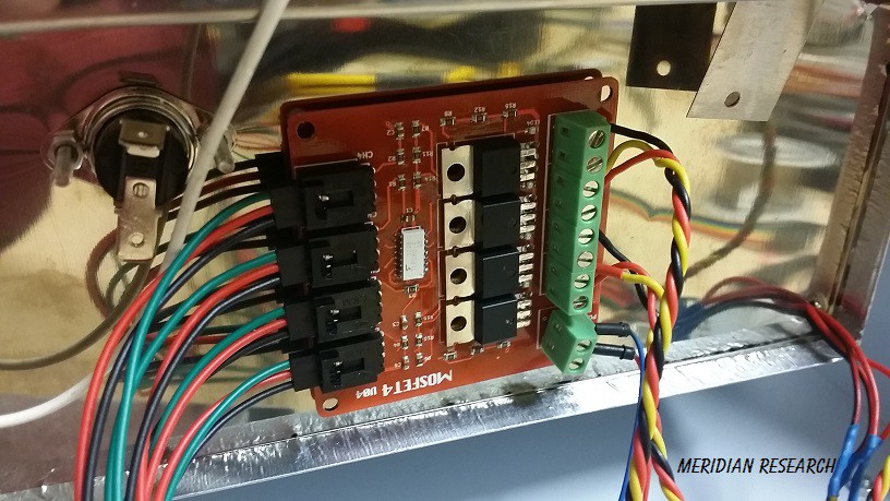
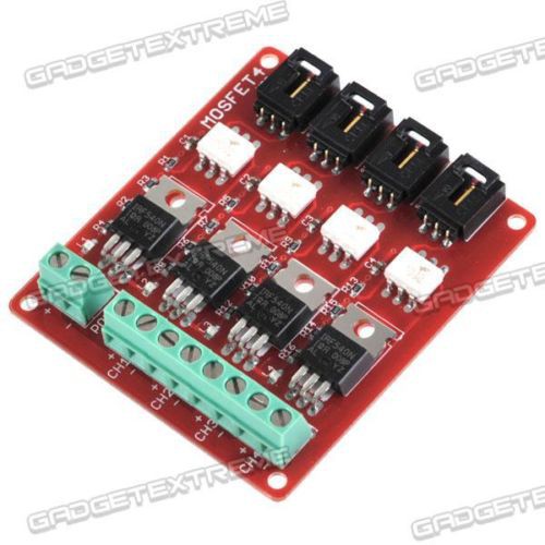
4 channel mosfet board... (I am lazy thank you.. Maybe I'll design a new one when I get this closer to being finished.)
$11.28 uses IRF5540s and is optoisolated... meh..
![]()
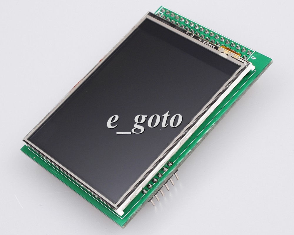
And a display... I wanted a nice touch display for mine.. It's not that expensive at $8 and makes for a way better look and ease of use, etc...
![]()
When this stuff gets here I'll get right to work.. in the mean time, I've been wasting my time with two other displays that I didn't end up liking... and well...everything else I have going on.. :)
-
Update
03/09/2015 at 10:16 • 0 commentsSo, I haven't been updating this (or my other) project(s) on a daily basis for a while.. I'm going to make an effort to do that... I don't think I will include logs for every single effort I make and every success and failure...instead, I think I'll keep a log (maybe weekly) of how it's going... and update the project to reflect where it stands.. And in the end, the project page will show a method to produce your own.. I just can't do all the work and update daily... I'd be typing all the time and not working.. :)
So, I will say...I have tried a couple methods for the UV Oven so far and don't like the first two efforts I made... First I tried some 3watt 365nm UV LEDs, buck converters all driven by a nice boost converter that fell short of my expectations... Ultimately it had a serial port that made it seem like you could control it from a MCU, but when I got it and tried playing around with it....the serial protocol has literally ZERO documentation.... I don't have time to weed it out and hack it out... I tried hooking a protocol analyzer up and saw that it transmits some pretty understandable stuff when it powers up, but again....no time...
Onto trial two... I skipped the 3watt LEDs mainly because they didn't live up to my expectations in brightness and coverage consistency.... so I moved on to try 200 5mm UV LEDs... Nope... too much work again creating the PCBs and so on to get them arranged properly, etc...
So, my new effort is directed at UV LED tape... I bought a spool of 300 or so UV LEDs on a few meters of flexible PCB tape similar to what you'd see WS2812s connected up to.. I'm going to try arranging them so there is nice coverage over the internal surface and maintaining as much of the reflective stainless steel inside as possible....I'm still waiting for them to arrive, hopefully this week...
I went back and forth a hundred times on which processor to use for this project.... I hate arduino's.. But I have a few laying around because they came with various things I've bought and replaced them... and this project doesn't have huge requirements for an MCU.... and everyone has access to them...so I guess I'll start off with one.. I tried an UNO first because it's cheap and easy....turns out that it doesn't actually have enough memory for what I want to do...Next up: 2560... Seems to be holding up ok... It'll be driving a display, keypad, the leds on a four channel msofet board, and possibly the power supply and a few relays.. The display and interface are what's going to take most of the processing power.. :)
So, I'll start posting some pictures when I get the LEDs, etc.. Keep an eye out!
DIY UV Exposure 'oven' for PCB etching and masks
Converting a towel warmer to a UV exposure 'oven' for making PCBs