Close
0%
0%

Metron

A digital microscope with machine intelligence.

Similar projects worth following
An old HP 7225A plotter from the trash, a cheap USB microscope, and a lot of odds and ends combined to make a powerful tool for engineering and reverse engineering printed circuit boards. Main goal is acquiring high resolution 3D scans of circuit boards via vision algorithms that exploit depth-from-focus.

Metrology is the science of measurement. The word comes from "metron" and "logos".

Purpose

Metron is a tool for automatically obtaining useful information from printed circuit boards, like:

  • High magnification live video with precise control of viewpoint.
  • Super-resolution scanned images.
  • Multidimensional super-resolution scanned images (multiple viewpoints from every location)

Such information is directly useful for manual inspection and reverse-engineering, but when combined with software that incorporates recently developed powerful computer vision and machine learning algorithms it can allow for nearly magical exploration of unknown electrical systems.

3D Models of PCBs

Taking advantage of two neat computer vision techniques called multiview reconstruction and depth-from-focus, Metron should be able to generate high resolution 3D scans of printed circuit boards. My hope is that these scans will be of sufficient resolution to distinguish the smallest of surface mount parts, pins of chips, vias, and the height difference between traces and bare board.

Extract Netlists

Once a high resolution 3D scan of a PCB is obtained it can be processed to extract useful information about the circuit structure of the PCB. Parts, pads, vias, and traces can be automatically segmented using a combination of visual and structural feature recognition. Some parts can be identified by reading their part numbers or matching them to known parts in a database. With all of the information put together candidate netlists for the circuit on the PCB can be generated and scored.

Semi-automatic Reverse Engineering

After as much information as possible has been extracted from the scans and run through machine intelligence the result will likely be very poor. Missing information caused by traces under parts, multilayer boards, mis-identified parts, scan errors, and many other factors will almost guarantee that the guessed netlists are very incorrect.

But an interactive system has some hope of reaching useful results. After the first run of processing a human can use the initial machine guesses to guide further analysis. For example, if the netlist is corrupted by traces being obscured under parts then the engineer can remove the parts and rescan those areas. With the new information better guesses can be generated and new analysis can be done. In that sort of feedback loop the errors in the shared human-machine understanding the target circuit can be quickly whittled down to zero.

  • Python <=> Plotter

    Owen Trueblood01/08/2015 at 20:21 0 comments

    Analysis

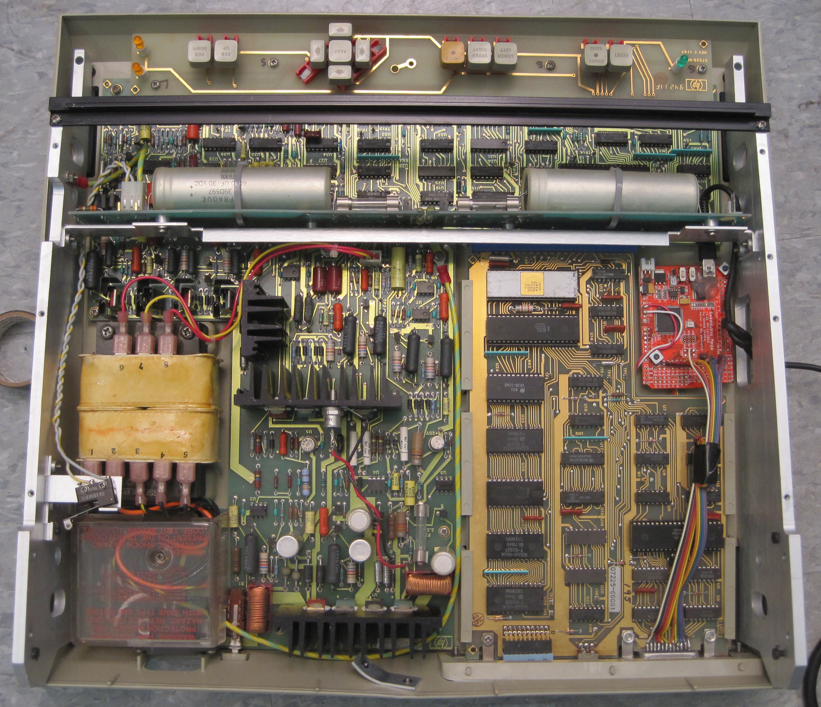
    Before making any modifications I took some time to understand how the plotter works. It is a nicely designed old machine that would have run you more than $1000 if you had bought it when it was new - in the 70s. There is a bunch of 7400 series logic on two of the four big PCBs to run the show. In the lower left is all of the power management. Most of the system uses 5 volts, but the vertically oriented board uses a higher voltage.

    The logic near the buttons handles the driving and positioning of the two stepper motors that move the pen head and drives the solenoid that lowers the pen. The buttons get their own board without any logic. It connects to the "motherboard" using a spring contact connector. The pretty removable card (17601A "personality" card) in the lower right is where most of the intelligence is located. The white chip is an F8 family CPUdesigned by Fairchild and manufactured by Mostek. The other chips include a memory interface, an EPROM, some 7400 series logic, and an interesting "general purpose interface adapter" chip (MC68488) that exposes IEEE-488 compatible communications via an M6800 compatible interface.

    The vertically oriented board with the two giant capacitors (1F at 30 volts each) is pretty interesting and unique. It is used to generate a static charge on the plotter's surface so that paper is electrostatically pulled flat. It is a really cool feature that I have no need for in Metron. Maybe I can figure out how to extract it for use in another project. Unfortunately the board combines that circuitry with the plotter head connectors, so I cannot just pull it out.

    Modification for Control

    After looking up information about the plotter and its circuitry online I knew that in its original use it would have been controlled by a computer with an IEEE-488 compatible bus. There are other easier ways to control the plotter (like RS-232), selected by swapping out the "personality card", but unfortunately I got a plotter with an IEEE-488 card. Thankfully, after a tiny bit of Google searching I found the neat agipibi project by Github user tibal. It lets an Arduino Mega serve as a translator between a PC and an IEEE-488 compatible bus (GPIB).

    Luckily I had a Seeeduino Mega kicking around in my parts bin from an old project. And serendipitously it fit perfectly into an space inside the plotter next to the interface card (space left for ventilation, it seems). All I had to do was solder a bunch of wires between the GPIB connector and the Arduino, find 5V and ground, bolt the Arduino down, and route a USB cable out of the ventilation screen in the side of the plotter.

    It took a little tweaking of the Python code to get a connection up because electrical noise causes the Arduino to reset several times before a successful connection is made, but after that everything worked as advertised. I can now send HP Graphics Language (HPGL) commands to the plotter and see it do my bidding.

View project log

Enjoy this project?

Share

Discussions

PointyOintment wrote 01/09/2015 at 00:18 point

I'm really excited about this project because a) it's awesome, and b) I've had an idea for a while of a machine to automatically disassemble PCBAs to salvage the parts. (The general idea I have so far is two opposable delta arms each equipped with a desoldering iron, tweezers, suction nozzle, jamming gripper, etc., with a controllable PCB vise in between.) I was thinking of possibly having it take data of some sort as it disassembles to enable reverse engineering, so I think my machine and yours would complement each other very well. They could even pass the board back and forth, removing parts and rescanning, like you said with a human.

Also, just a small thing: I think you're maybe a bit optimistic to hope to distinguish the height of the traces from the height of the board using depth-from-focus, because there's not much to focus on except the edges of the traces. But I'm not an expert on it, so if you can do that, that would be amazing.

  Are you sure? yes | no

Owen Trueblood wrote 01/09/2015 at 18:30 point

a) Thanks

b) A machine like that would be useful. Maybe the iron / tweezers / suction nozzle could be replaced by hot air? But I love the idea of using a jamming gripper. I have wanted to make one of them to play with ever since I saw the concept demonstrated a few years ago. It would be fun to try to shrink one down enough to grasp SMDs and other really small bits.

Instead of passing the board back and forth, I'm sure that all of the functionality could be integrated into one machine. The tool heads on the delta arms could carry cameras, or they could be automatically swapped with cameras. The thought of how that would look makes me want to build my first delta arm.

Such a machine would be useful, but I'm not sure if the difficulty / payoff ratio makes sense. PCBs can be disassembled easily by hand with the right tools. An automatic machine would make it more pleasant, but would be really expensive and unlikely to be robust. I think that the analysis side has a worthwhile difficulty / payoff ratio because figuring out what a circuit does is nearly infeasible for any nontrivial circuit (and there are a lot of those in our everyday lives, and they are usually where the interesting stuff happens).

On distinguishing traces with DFF, you are definitely correct that I am being optimistic. It is unlikely that the optics on my crappy USB microscope are of high enough quality, and my z-stage capable of fine-enough motion, for the height of traces to be resolved. But I know that it is possible in principle: (the company that made this picture, Halcon, does much of what I want to accomplish, and more).
  Are you sure? yes | no

Similar Projects

Does this project spark your interest?

Become a member to follow this project and never miss any updates