Joshua Vasquez
-
The Obligatory Side-by-Side
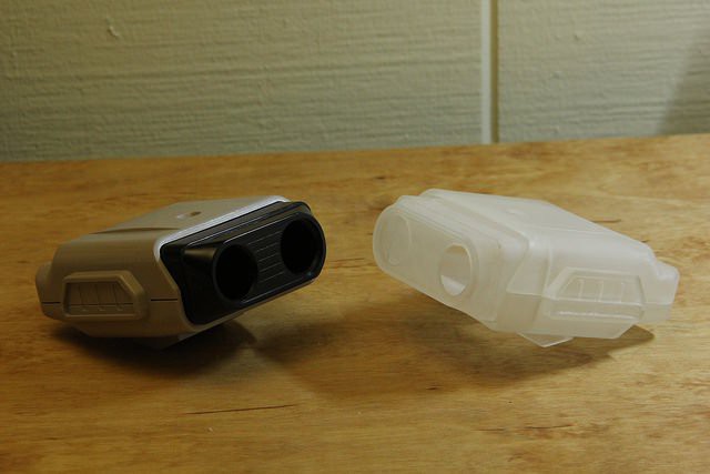
03/05/2015 at 08:37 • 0 commentsWorking with just calipers, I did my best to guess the sizes of the fillets. Overall, it turned out pretty well! R.O.B's new head is 3 parts printed on a Form 1+. I have to admit that I really like the workflow that the printer can offer. Most of the parts were printed while I was asleep :)
![]()
Overall Form 1+ prints do tend to distort both from there own weight and from the "peeling step" as each layer is being printed. Luckily, the parts aren't fully cured when printed, so I can ensure that they'll fit together before curing them completely. I'm still learning the tricks of the printer, but I'm impressed by how quickly I've been able to get results.
-
R.O.B. Recapitated
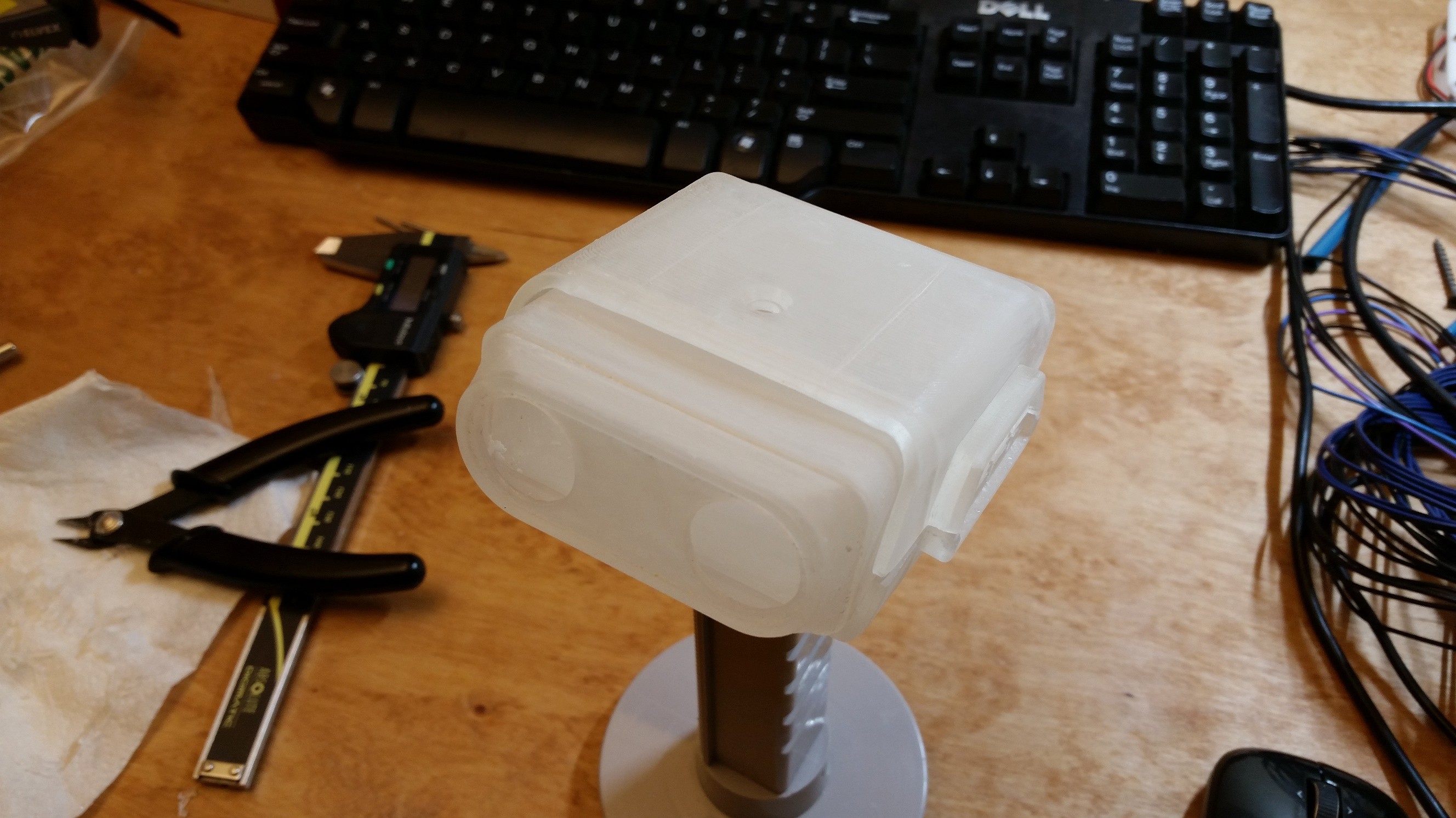
03/01/2015 at 02:19 • 0 comments3D Printing is very much a craft that I have yet to master. Here's my first shot at printing the head model (3 pieces) and wet-sanding it lightly with 320 grit. Oddly enough, the new version actually fits cleanly onto the old neck from the model I've borrowed.
![]()
-
CAD Progress Part I
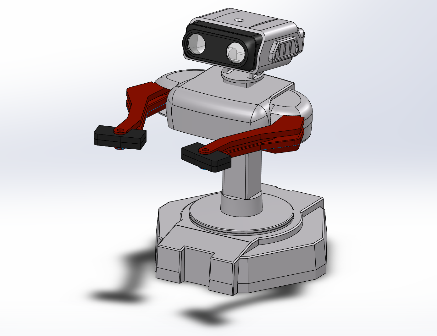
01/24/2015 at 08:29 • 0 commentsProgress so far has been a firm lesson in surface modeling (as opposed to modeling with solids) in Solidworks.
I'm currently debating on fabrication techniques for the shell. So far, I'm looking to either 3D print the shell itself with a resin-based printer or 3D print molds from which I can cast a fiberglass replica.
I haven't run any calculations yet to figure out whether or not the 3D printed material will have sufficient strength to take a few bumps from driving it around. If not, I might consider a DIY attempt at electroplating to increase tensile strength since most of the parts are thin-walled.
A fiberglass composite casting would be more-than sufficient to take a brief beating, but I'll lose the convenience of adding internal features to the inside since I'm only casting the outer surface.
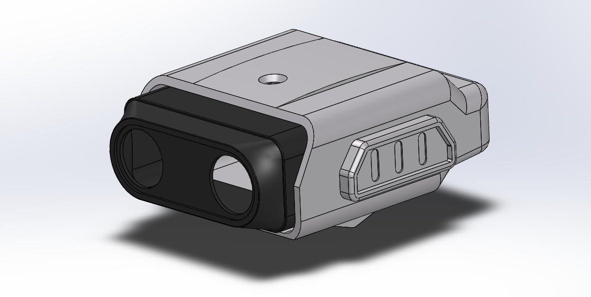
Random thoughts aside, here's a quick peek at where he's at so far:
![]()
(R.O.B. sold in Japan arrived boxed with a slightly different color scheme)
-
CAD Modeling Techniques
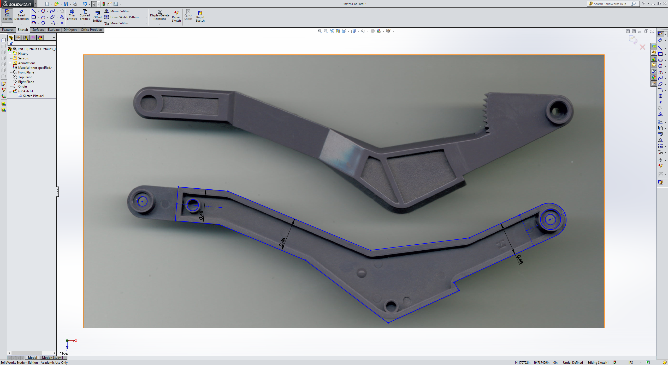
01/14/2015 at 07:18 • 0 commentsThis technique isn't anything new, but it definitely has a place in capturing R.O.B. from his original pieces. With a scanner handy, I took copy of the inside of R.O.B.'s left arm and imported the image into Solidworks. From here (or with any vector program, like Inkscape) I can capture some of the relative distances between features and scale to a known dimension. There are some caveats to this technique: for example, the scanner really only reveals distances for features at a constant height away from the scanner. For this reason, capturing flat features is my primary use for this technique. Furthermore, I wouldn't use this technique for 0.001" accuracy, but in this case, it's good enough.
![]()
If you have a CNC (or manual) milling machine nearby, you have the option of a similar (and far more accurate) technique than this one here: you can simply clamp your part into the vice and index all of your features by moving the mill head to each feature with a tool like an edge-finder.
-
Head Shell 1st Pass
01/10/2015 at 19:58 • 0 commentsHere's a first pass of the head. Right now, I'm aiming to break down the original model into its characteristic features. Most of these features are easy to extract, like the fillets that round the edges of the overall shape. The tricky part is nailing down the order in which these fillets were put into the original model. For the most part, the fillet dimensions appear to be fractional values from the imperial scale (i.e: 1/8th, 5/16th, etc.). So far, all fillets look acceptable and characteristic of the original except for one set of fillets in the lower corner. The only way to tell the difference, though, is to do a side-by-side comparison of the original model. Otherwise, the overall features look very acceptable.
Since I'm only using calipers, I don't expect my estimates of angles to be spot on. That said, if I do happen to pick up the right tool to measure angles and fillet radii, I can readjust them later, provided that I include them all in the CAD.
Lastly, I'm only modeling the outside of R.O.B. with tight tolerances and detailed measurements. Since I'm investigating how much space I can squeeze out of his interior, I'll leave out the channels and ribs on the inside of the model unless I need them later.
![]()
Until then, cheers!
-
CAD Prologue
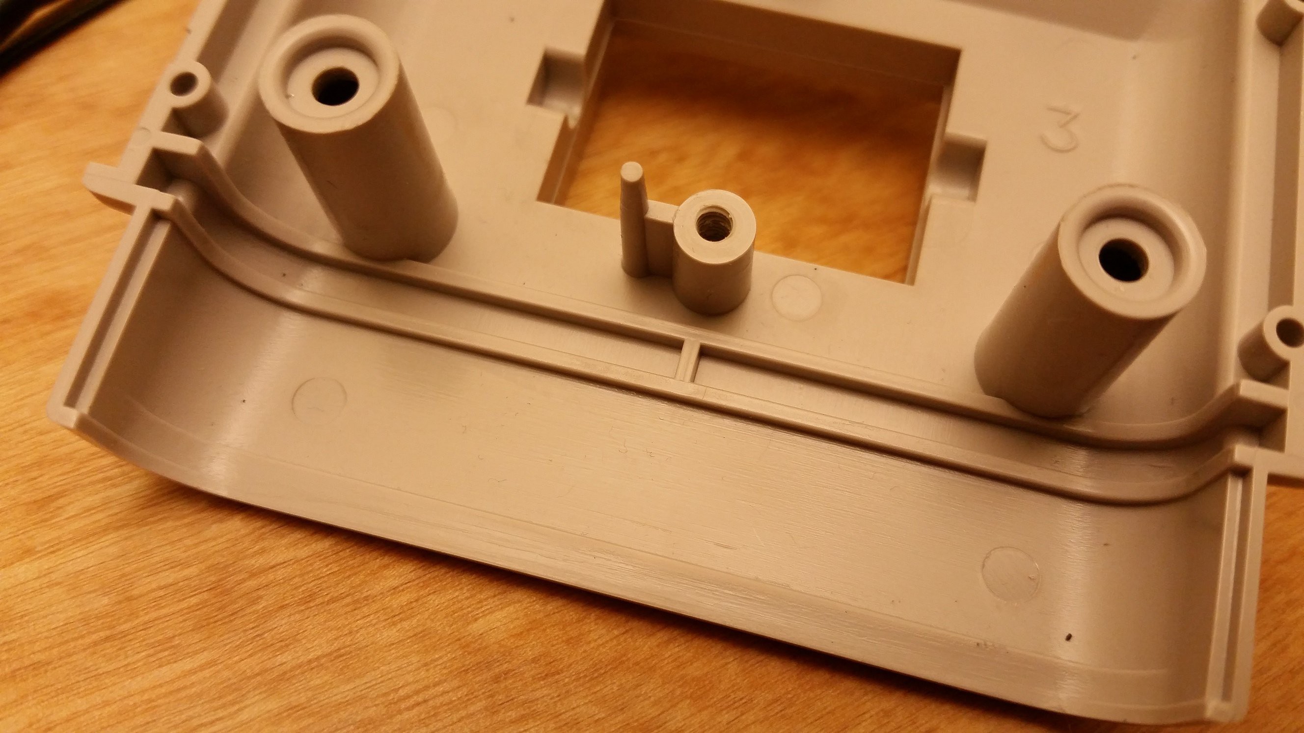
01/10/2015 at 08:46 • 0 commentsTo start leap forward from 1985, I'm assembling a CAD model. I'll sacrifice a couple minute features, but I'll do my best to nail the overall dimensions. As I start the CAD, I've already noticed a few odd features:
- Nintendo hails from Japan, but many of the dimensions (3.00[in], 0.3125[in], etc.) are imperial. (Could the R.O.B. model designer be American?)
- Outside, R.O.B. looks clean and polished, but on the inside of the shell, I can see some interesting grooves and patterns on the ABS. I suspect that the original R.O.B. model, from which all copies were formed, was carved from either wood or clay since these patterns seem to have taken on the impression of a block of wood or sculpted clay. Judging by the outer shell, R.O.B. may have first been vacuum-formed from a solid template block (wood or clay?), after which a mold could have been made from these vacuum-formed pieces. I don't have the manufacturing skills to be certain, though.
![]()