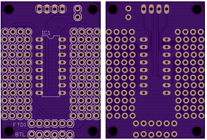
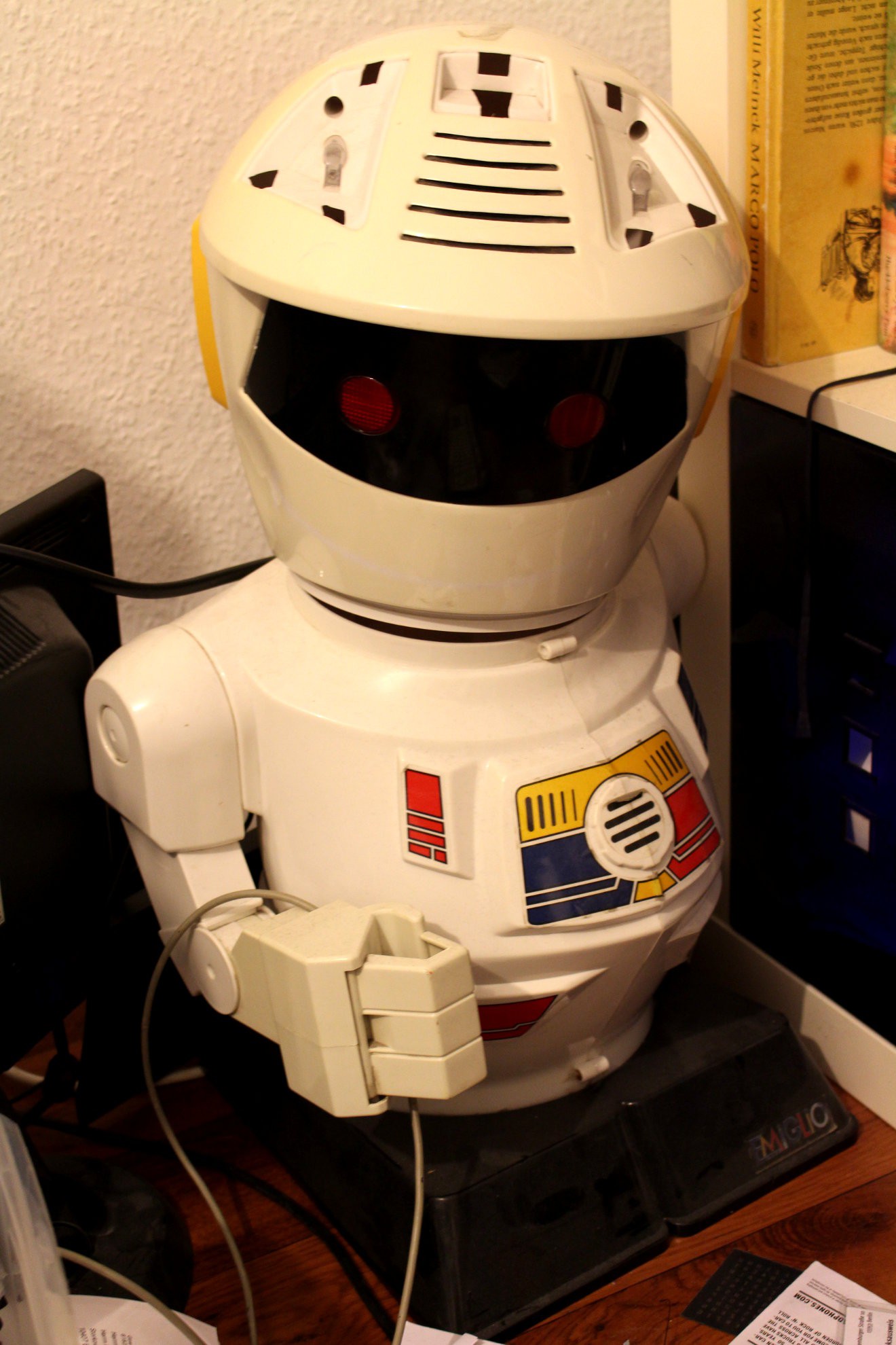
I started soldering the motor controller board for R8 today, and realized that I'm totally spoiled by designing and ordering boards from OSHPark. There are 2 other robotic projects I consider working on, that would also need a motor control at some point - the magical number 3 (boards) of ordering at OSHPark. There is the already infamous BB-8 / R0-T8, the rolling bot from the new star wars installment "Episode VII" for that I've ordered a 20cm plastic ball, matching the size of a 12cm dish. I can't believe that already know its both names. The third robot in need of a controller would be Emiglio, a not so little robot I scored on eBay. One gearbox is broken and pretty much all the electronics where not reusable.
There are probably some open source robotic platforms I could try out, that work with arduinos, but I always end up doing my own stuff. I should at least push all my code, pcbs and 3D parts online. The shield I designed has the GVS feature that should allow for some easy servo installation and should be plug and play to the serial bluetooth dongle I bought at eBay. This makes it possible for some Android apps to control it.
I hope I manage to power R8 by one of four 2750mAh LiPo cells I harvested from a broken macbook with a boost converter to 5V, but I have to measure the current of the motors and the arduino + bluetooth module to figure out if the boost converter will be able to give enough power. If not, I would have to use a second one in series and separate the power supplies for the controller vs. the motors.
Is anyone of you using the rectifying diodes with the L293D? I've never seen them in a diagram/schematics before, so I was surprised checking the datasheet. Anyway, I've ordered those purple beauties. I know, I said I wouldn't order boards after midnight, but I've checked all the connections this time. A prototype is something I still have to solder though, since I want to see some progress with R8.

 davedarko
Discussions
Become a Hackaday.io Member
Create an account to leave a comment. Already have an account? Log In.
Your "Third" method is my "second" method ;) But you're OK, since you've got the D-series.
Also, with your three-wire method, you can implement "braking" which is handy, at times... (drive both H-Bridge halves to the same voltage, effectively shorting-out the motor-windings).
And now you got me thinking more about the effects *on the motor* of using diodes. I think it differs than solenoids. Usually the solenoid diode goes *across* the solenoid's windings, whereas the diodes in an H-Bridge connect the windings back to the power-rails, so there isn't really the same sort of *loop* made with the diodes and the motor-winding.
Also, since motors can act as *generators*, and since the motor is spinning when the PWM is removed, it would essentially be acting as a generator... I can't quite picture it, because it's also acting as an inductor, and... maybe I"ll hook up a 'scope sometime ;)
(And, now, I'm remembering there's *two* ways to connect a diode to a solenoid driven by a transistor, one across the windings, another across the resistor, Very different effects, but both effective at suppressing the voltage-spike).
Heh, sorry, TMI, I bet :)
Are you sure? yes | no
I've never *not* used the diodes with the L29* motor drivers... But I also use fast PWM and most my projects are close to the current-limit of the driver chip, (and I haven't really used the L29* series very much *because* of the diodes).
From a *technical* standpoint: If you're using slow PWM you could probably get away with regular diodes (rather than high-speed). And if you're not using PWM at all, you could probably get away without diodes at all.
From a reality standpoint: I honestly don't know what would happen if diodes weren't in the circuit. Supposedly inductive loads can cause huge kick-back voltages that can easily fry electronics and hurt alot if your finger happens to be in the circuit. I've *definitely* seen this with solenoids--one of my early electronics projects was a relay connected to a 9V battery through its own Normally-Closed output... two wires sticking out from the coil made for a fun "shocker" toy that coulda gotten me kicked out of school ;)
As far as *motors*, though... I can't actually remember experiencing the kick-back from a motor's windings, now that you mention it.
I did build a home-built motor-driver once *long ago* that used mosfets rated for 60A, and was only driving about 12A, and despite the huge heatsincs it burnt out after only a couple minutes. I'm not certain what I did wrong, but I certainly don't *remember* thinking about adding diodes. (I copied the schematic from online). The other possibility is that the PWM frequency was too high for the MOSFETs, so both the high and the low sides were on briefly as the circuit switched polarity.
I'm certainly open to hearing about L29*s used without diodes, as I think they're a pain in the a** ;)
Are you sure? yes | no
Comment, I chose you! I just checked the datasheet again, and now I finally now what the D in L293D means - diodes :D But thank you for this post! I was not aware that the actual speed of the pwm would be important, too. Once again I learned something on hackaday.io :)
Are you sure? yes | no
Oh, sorry for the double-post.
I see now. I didn't realize the L293 (without a D) existed. Nice. That's what I get for getting my parts via surplus sales ;)
It also occurs to me that there are two ways of driving most motor-drivers... One is to *flip* the polarity of the H-bridges with PWM, another is to *disable* one (or both?) of the half H-Bridges when the PWM is off. In the second-case the diodes may be more necessary than in the first.
And, yeah, if you learn anything from my comments, it's that I often go about things in my own way... That's how I learn. It's a bit slower (and apparently a bit more expensive) than using things the way most people already figured-out. Also, obviously, it means that I sometimes miss-out on things like cheap motor-drivers that already have diodes built-in ;)
(For reference: I started years-back with the LMD18200, which costs $17 apiece!)
Oh, one other thing:
Without diodes:
With a solenoid, anyhow, if you drive a solenoid with PWM, you'll quickly find that it's *much* stronger with diodes... The current has a place to go, and it feeds back into the winding, thus allowing it to *continue* its magnetic field, rather than dissipating (nearly) immediately between pulses. The same *might* be true for motors, and I'm certain it's true for *stepper* motors.
Are you sure? yes | no
Hm, is it a third method when I pulse the enable and use 2 extra outputs for going forwards and backwards? I seem to could have used an inverter to switch between left and right. Naah, too late for that :D
Well, my technical knowledge is based on the self-taught stuff my dad told me and this dangerous place of half-truisms called "internet", so any comments from an "experienced-in-electronics" person are welcome here :) That's a lot of money for a single purpose chip.
Maybe when I switch to solenoids with my #Locomatrix - 3D POV - a different approach I will get back to those extra diodes.
Are you sure? yes | no