convert Palm foldable keyboard to USB
from my Palm Pilot days I have some of those foldable keyboards lying around and try to find a way making them usable via USB
from my Palm Pilot days I have some of those foldable keyboards lying around and try to find a way making them usable via USB
To make the experience fit your profile, pick a username and tell us what interests you.
We found and based on your interests.
board_redraw_dimensions.dxfboard dimension as dxf-fileAutoCAD DXF - 123.62 kB - 02/06/2025 at 21:44 |
|
|
board_redraw.dxfdxf-file board without dimensionsAutoCAD DXF - 100.85 kB - 02/06/2025 at 21:44 |
|
|
Anschluss_Tastenmatrix.odskeyboard to jumper matrixspreadsheet - 17.99 kB - 02/06/2025 at 21:42 |
|
|
Anschluss_Tastenmatrix_en-us_jumper.odskeyboard to jumper matrix_english versionspreadsheet - 12.49 kB - 02/06/2025 at 21:42 |
|
I tried different ways to get the dimensioins reverse engineered.
Scan it, import it to inscape and trace the outlines by hand worked somewhat akwardly, because I never got the dpi conversation fitting.
So I now do a mix of get the outer dimensions and sice of teh hole old fashioned with a caliper and used an usb microscope for the dimensions of the connection pads. That seems to work fine:
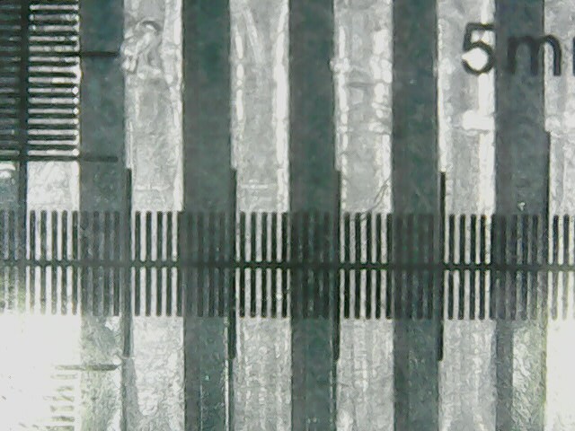
To my pleasure and suprise it's metric. You see a snap from the microscope which comes with some transparent scaling "thingy". (big lines 1mm, small ones 0.1mm). So I will do some CAD work for the dimension before I dig in the PCB design which I haven't entered before...
Oh, and I#m thinking about to put an optional connector for the thinkpads on the backside and perhaps some holes for standard headers for debugging in the area on the board which can't be populated when used inside the case.
I removed all components from the original PCB to get a good scan from it and to find out wher and how much space is there to place components there.

It's about 65 to 20 mm in square. (exact measurements and scan to follow).
And here the same with the top cover flipped:
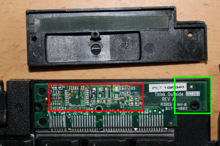
The board was populated on side only. The reason is the backside is lying nearly compleedly tight to the plastic housing with the only exeption beeing the part in the green marked area, where aspace of about 2mm is beneth the board.
the red marked area is where the components where paleced/ could be placed. There is a max of 3.5 mm in hight in the middle area, slping down to 2.5mm to both sides (to upperpart is what goes on top of the board.
The foodprint of the U1 is 7mm square for the housing, which is the sice of the QFN foodprint of the atmega32u4 chip, which is my faveroed chip for this poject because it has USB on board and is arduino compatible, so it could be used as mc itself or could be flashed with the arduino bootloader.
I'm currently thinking of double using this PCB for an USB -thinkpad keyboard adaptor, too. This would mean to place the according socket for those keyboards additionally onto the board, what will result in some space issues.
I can think of some solutions to this:
A) place all components for the palm keyboard inside the red area and the thinpad socket on the other side of the PCB and leave it unpopulated for the palm use. Will need to track 2 paths for the populating, but simple enough since it's just dropping a part.
B) place the little SMD parts, the thinkpad socket and the USB socket inside the red area and the atmeag on the other side of the PCB. Would require cutting a hole into the case where the atmega will rest in. This would give most space for routing the PCB, I'd think.
C) mostly ike B) but placing the atmega on the backside of the PCB fitting inside the spare gap in the green marked area. Most likely will give too little space for routing.
There is also the idea of having alle pins routed to standard plug connectors (like the ones at the arduino shields), most likely as option for debugging and not fitting inside the housing.
So I thougt to give the teensy I had in stock a run. (basicly because I got the information it's able to appear as a HID (USB Keyboard).
To make space for that, I removed the all parts that make the Palm stand and made some holes to fit the wires and connector.
Left the teensy inside the keyboard, right the orignal space with the Palm stand for comparison.
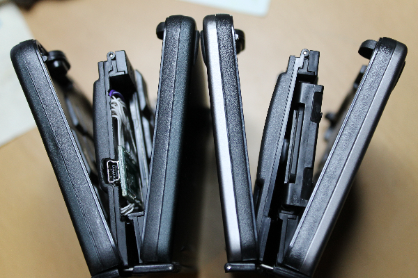
And here is one opend from the backside (I had to cut of half of the little plastic nob on which that part rests on the table).
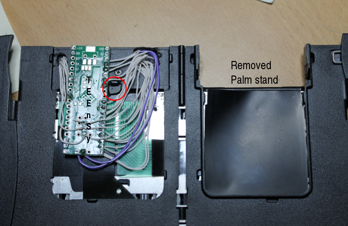
wiring is a bit ugly, but I thought it'll do for fisrt run. The other side is ever more difficult and I daaditionally needed to remove the reset switch from the teensy and wire it to the top, since I would otherwise had press it with most of the keyboard strokes, which pressed the switch underneath.
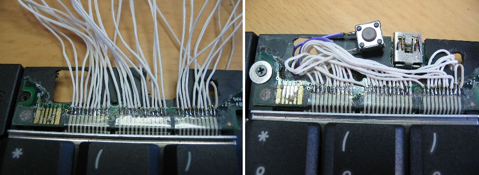
I drilled a little hole in the top of the case to get the reset switch pressed with the bended paper clip Trick.
As you can see, I cutted of all parts of the PCB to have only the contact pads for the wiring left. The rest was a little sketch (with the help of the arduino forum and sisam), to go for a test run. It BASICLY worked, which means I got some (but not all) keystrokes, but never random or false respond. So I guess I possibly riuned some contacts by soldering temperature, or mechanicly while several dis-/reassambling or simply broke some of the ribbon cables. But all in all I count it promissing enough to go for custom arduino (or at lest a breakout board first), which will the replace the cutted down original one and will use the z-axis conductive tape.
In the above setup the housing squeses on the the soldering pints, which is a additionally source of possible connecting problems.
After fiddeling around with some weired adapterchains trying to get some serial to usb working, I decited to look inside.
Above the 4-7 keys the connector for the Plam pilot is visable (can be unfolded to a stand for the device) and above th 8-0 keys is the housing of the PCB. 2 screws are visable from top:
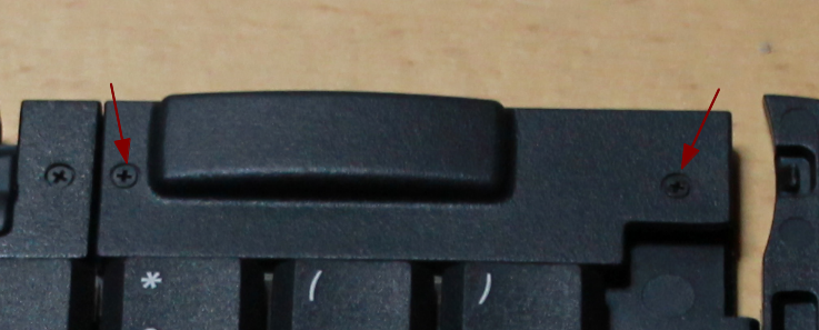
But there is a hidden one on the bottom side:
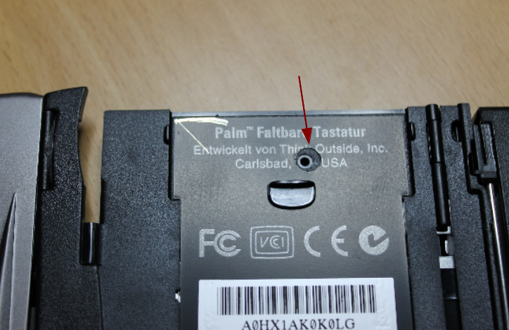
This is tricky to find, since the hole in the picture made by me. The label hiding it is not a simple sticker, but actually a thin metal plate glued to the plastic. I carfulle removed it (trying to bend it as little as possible), punshed the ole with a simple office hole punsh and put it back in place (the glue seems to be a contact adhesive one, so tha worked quite good. Maby now, knowing where the screw hides, it can be achived by using a tine curcular saw aswell.
An finally we se what's inside:
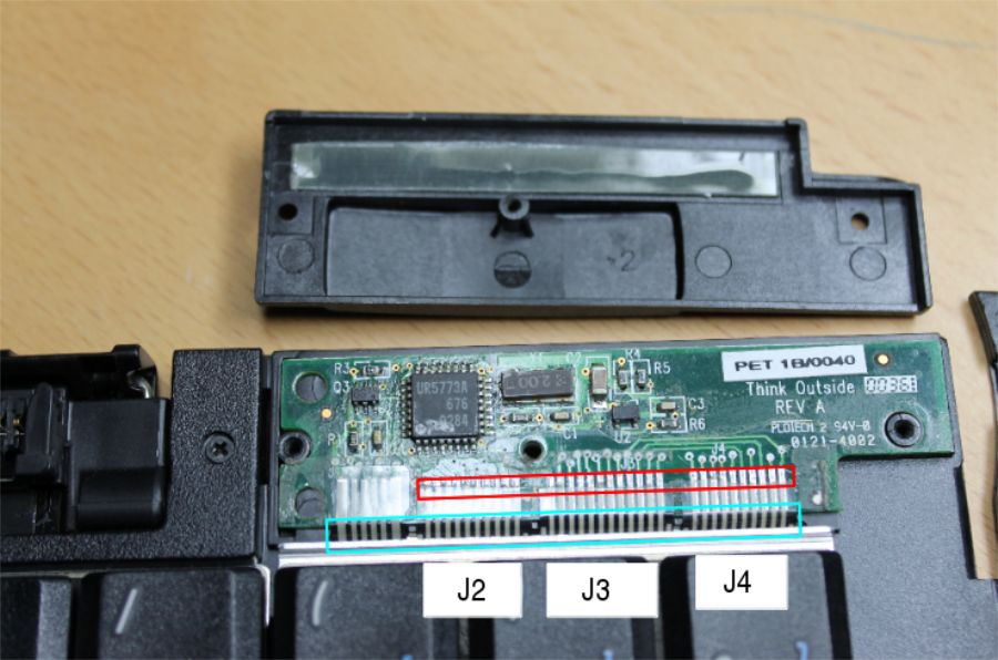
the cyan marking show the 4 lanes of wire, which are connected to the PCB by using a double sided adhesive tape, most likely this one:
http://www.adafruit.com/products/1656
blocks J2-4 are the ones connected to each subblock of the keyboard. The (not labeld) J1 is connectet to the Palm connector. I then spend some tedious work to decipher the matrix. I partly removed the flat ribbon in the rad marked area and used a circuit indicator on the pads. I started with holding the testing points on J1 pin 1 and 2 and started pressing keys until I had a beep, wrote that down in a spreadsheet and the tested J1 pin 1 and 3 and so forth (you get the tedious part, I guess).
But after some patience I finally had the matrix layout for the US and German keyboard (have to upload them some where..)
Create an account to leave a comment. Already have an account? Log In.
The original schematics are closed source by palm. I do have the the schematics for the newly designed (by Hamish) board, whih sadly by my fault has one mounting hole missing. I was also thinking about the 328p, becauseof the USb onboard thing. I#ll try to think of uploading the schematics from Hamish.
I suppose the original board has just two layers so you can easily reverse-engineer it.
In fact you don't even need an onboard USB as you can use Usnoobie and V-USB.
By the way, have you seen the alternative way?
https://github.com/cy384/ppk_usb
I've managed to fit this board on the original connector by cutting some plastic from it and cutting one edge of the board. So I didn't have to remove the original "cradle". But I'm still very much interested in implementing this project with a V-USB library...
the original board is at least 4 layers from the look of it.
I haven't seen the alternative so far, thanks for that. The idea of my approach is to have no extra dongles to care of plus the idea to make the same board available for the thinkpad keyboards (the one from the old laptops). The guy I was thinking about this in the novena board has somewhat little time to go ahead and I have no skills in PCB design. So if you have, I'll happily supply you with the layouts he has done so far. Perhaps best by providing them here for download and you joining this project?
In fact with pro micro (and, probably, pro mini) you don't need any dongles and you can even leave the original cradle in place. Just remove some plastic from the palm connector and cut the board a bit, see the picture: 
Can you share schematic of the original board? I wonder if this controller could be replaced with 328p one.
actually it was the 32u4 one that has USB onboard (re-read my own blog post...) and has the right foodprint in the QFN package, but I'm not sure if the universal board for this and the thinkpad keyboards is doable with that.
Thanks for documenting your efforts. I have one of these keyboards and I've often thought it would be fun to use with other projects. You work will make it easy to find a new use for my keyboard.
Hey, looks like you're going the route of replacing the built-in microcontroller? Well, if you decide to keep it, this page might be handy:
https://sites.google.com/site/geekattempts/home-1/commoncode/hsstowawaykb
Note, at least for the Visor, the power was supplied to the keyboard via the Tx pin. Note also that it was rated for 2.7V...
Good luck breaking free from the cloud!
Yes I intent to go to a replacement of the original controller to have it USB (and maybe bluetooth) connected. Most likely it'll be some arduino compatible, if speed isn't an issue.
What the hell. I just pulled mine out of storage an hour ago.
Did you find a golden ring resently and just after putting it on you thought of it ;-)
Stay tuned, I'll try to speed up my writing to what I've done so far..
Become a member to follow this project and never miss any updates
Stumbled across this while researching trying to bluetooth a couple of old palm k/bs. Can't stand/use the modern small portable keyboards - I've got big fingers.
Like you I don't really want to have lots of add-on plugins to cart around.
Maybe I'm being too timid, but how did you get into that compartment with circuitry without damaging the compartment lid?
On mine having undone the screws the top stays in and I'm guessing there's a one time plastic peg on the "lid" to hold it sealed, probably what looks like a plastic foot on the rear of that section.
Same Q for the side with the rest. While I have a spare I'd rather get two usable k/bs than one and a few spare pieces.
On a completely different question has anyone ever seen these with a UK keyboard layout (or at least keys with UK keyboard combos such as 2 & ", 3 & £ and @ & '