Eric Hertz
-
Link[ed!/s]
05/23/2021 at 19:11 • 0 commentsHey hey! We got linked! Thankya @dearuserhron and @Arsenijs!
#All About Laptop Display Reuse
Also, this project, frankly, I forgot that I had, here, so most recent updates regarding avr-lvds-lcd and similar hacks are in logpages over at: #Ridiculous [LCD] Display Hacks
And, since I'm obviously having a hard time keeping my display projects organized, I'll throw this here, too: #(VFD) Panel-filter
The idea is to remove the backlight from an LCD, and use it as a color filter for various purposes, e.g. stage-lighting (spotlights) or as a color-changing overlay for other display technologies like VFD, B/W CRT, or even analog gauges.
-
Repaired
10/16/2016 at 07:59 • 0 commentsSome months (years, now?) ago, I managed to rip the ground-lead out of the CCFL tube. Whoops!
Turns out the lead into the tube was fine, just the wire broke off the solder-joint... So it was a relatively easy fix. And now it runs again! In the simple binary-clock form shown in the main images.
Though, it's kinda fun to revisit the last log... wonder why I never got around to that... I dig the colorful "abstract art" aspect of it :)
-
"Holy balls, does that ever look awesome."
04/08/2015 at 18:03 • 8 commentsAlright, so it's not exactly a *binary* clock, but @Benchoff's project does look awesome...
If you like blinky-lights, click here: http://hackaday.io/project/5156-rgb-seven-segment-clock(UPDATE: See more conceptual-pictures below)
So.... a brief brainstorm...
It might be darn-near plausible, if not probable, to accomplish this sorta look with the system driving this LCD-binary-clock...
Again, it's absurd, maybe, to use something like an LCD with such high-resolution potential for something that could be done with LEDs designed for the job... but therein lies a challenge that appeals, a bit... Not only does it look cool because it's colorful, but also because it has that very clear 7-segment feel *while* being colorful; the angled edges, whatnot... I dig it. (Also, I kinda dig the brighter glow in the middle of the segments, but that's not realistic with this system).
Attempting something like this with this LCD thingamajig?
Well, first... masking,... that'd take care of some of it. But with the huge square pixels used in *this* system, as-configured, I don't think it'd be able to handle the angles of a seven-segger where three segments meet.
Several ideas:
- Masking
- (Row-segment buffer, for high-resolution)
- ROTATION (for those 3-segment corners!)
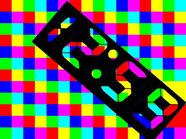
This is *VERY* quick and rough... But maybe the idea can be gotten from this:
("Mask" generated via Gimp from an image at the link, above. @Benchoff, hope you don't mind!).
![]()
Some work, obviously, would have to be done to align things better (I really only focussed on the '9'). Don't forget that 7-seggers generally have a *slant* toward the upper-right, slightly italic. Apparently that's quite a bit more complicated to work into square-pixels. Also, note the verticals are shorter than the horizontals... Another consideration, which makes square lighting a bit more difficult...
And, some vague idea that the mask would be intentionally movable, so that it just looks like a random color-pattern except when the mask is positioned properly...? (I guess there'd have to be lots of black pixels in that pattern)
Some finagling could be done, as well, with changing the number of pixels in either direction (within reason, there's only 512B of RAM!)... even, possibly changing the heights of *certain* rows... (And then, of course, there's always the possibility of the "row-seg buffer"... which could pretty much handle all this, with a bit of work... Maybe it could be used with roughly-random polygons and a movable-mask... intriguing)
------------------------
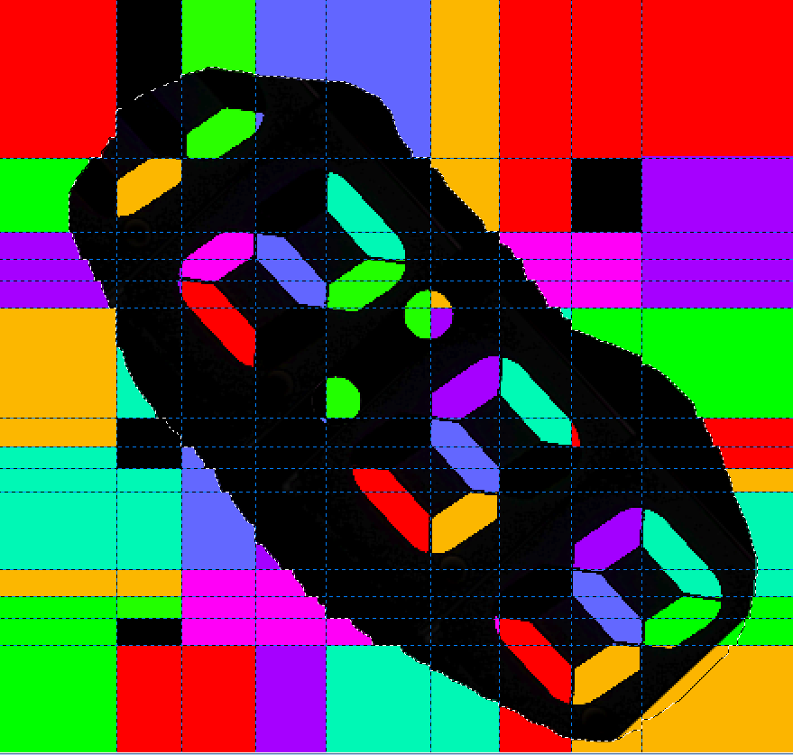
Here's some more Gimp-Experimentation...
Key Concept: There's absolutely no reason whatsoever why the pixels have to be square... Nor even consistent in height (though, width is quite a bit harder to mess-width, *especially* if not in columns).
![]()
The (majority of the) black blob,, again, is a mask... it could be laser-cut or something....
(The gridlines show the potential shapes of the pixels on the screen, they obviously vary dramatically, mostly in height. Width is harder to vary, as it's generally handled by Assembly-instructions for the fastest possible refresh-rate. But there're ways to tweak it a little bit, if necessary.
I think it's *just under* 16 pixels in *both* directions, so, no memory problems, even with a full frame-buffer :)
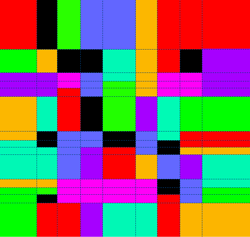
Below is what it could look like without the mask:
![]()
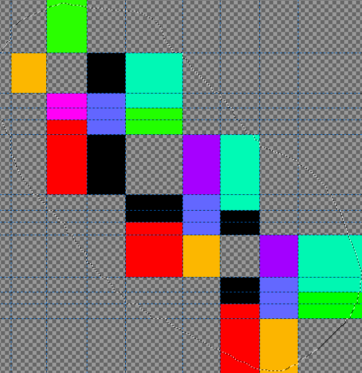
These are the *relevent* pixels...
![]()
Of course, there's no reason the *text* has to be diagonal... the display itself could certainly be rotated to make the text horizontal... There's no reason the rest of the display needs to be visible, either... it could be completely masked except where the segments are located.
Anyways, it's more a mental-challenge than anything else... opening up new ideas for how to make use of/improve this circuitry/software.
-
kit?
01/20/2015 at 00:46 • 0 commentsThis system could easily be developed as a kit... Just solder-up some through-hole components and connect it to an LCD...
Do you think people'd be interested?
---------- more ----------While working on this project, I've also been in-contact with someone interested in LCDs who happens to also have a (young) kid... It occurred to me that this entire system could probably be thrown into a kit with an LCD for around $20-30 in parts. (So, I guess I'd ask, maybe $50?)...It'd consist, maybe, of an unpopulated PCB, an already known-functional display, backlight-driver, a preprogrammed AVR, and the other support-components.
...
I'd been *trying* to make the LCD-driver software step-by-step enough that most interested tech-savvy folks could get the system working with whatever random LCD they have laying around... but that's a bit of a stretch, as different displays have different characteristics. I know the system inside-and-out, and it usually takes me two to three days to get a new display working. (OTOH, I do take the slower-route, as doing-so helps to figure out its unique characteristics that could be taken-advantage-of for new design-ideas... as well as also being slowed by spending a bit of time revising the "step-by-step" instructions as I go).
That level of dedication is probably hard to come by, as most people with that level of tech-skills are probably out developing/hacking their own projects...
But, if I settled on a particular display, then I could leave coding to the "advanced" users, if they chose to go that route... So, then, kit-wise, probably a 7-8y/o could assemble this... and then even code up their own ideas later down the road. It's an idea I'm mulling over.
I'm definitely open to thoughts!
avr-lvds-lcd binary-clock
A dead laptop's LCD, An ATtiny85, two 74LS86 XOR chips, and my first binary-clock