-
Solder Haze
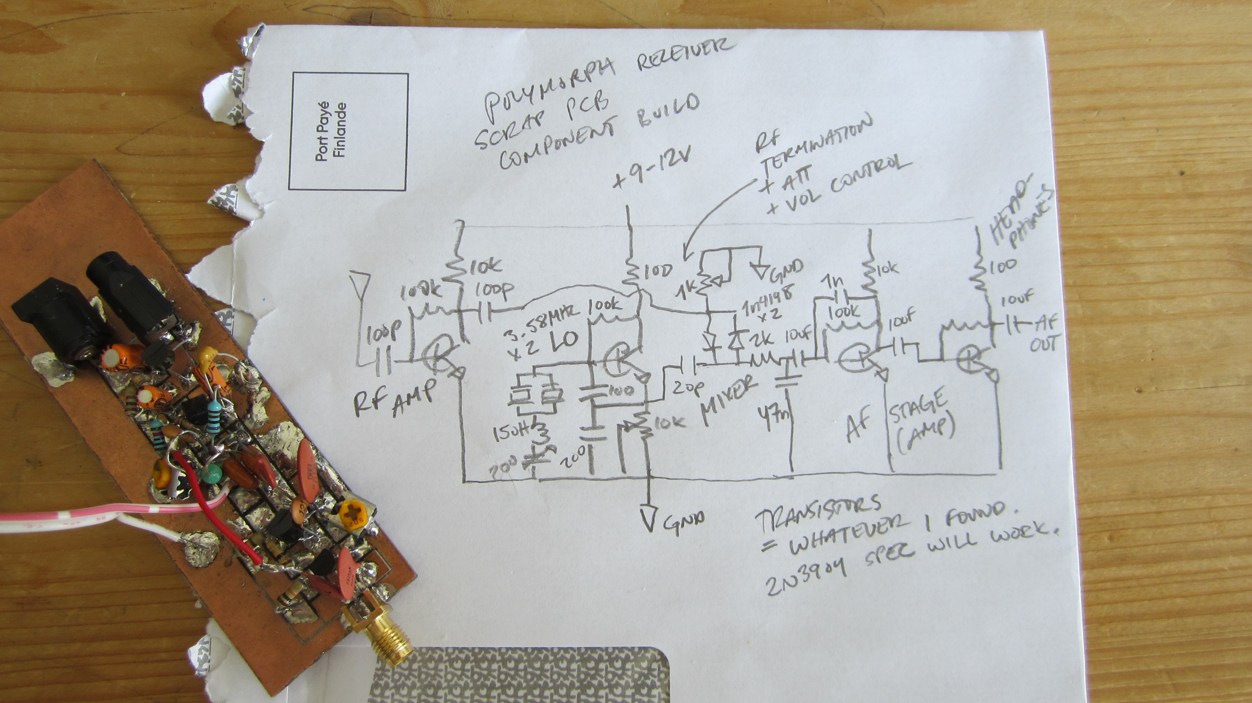
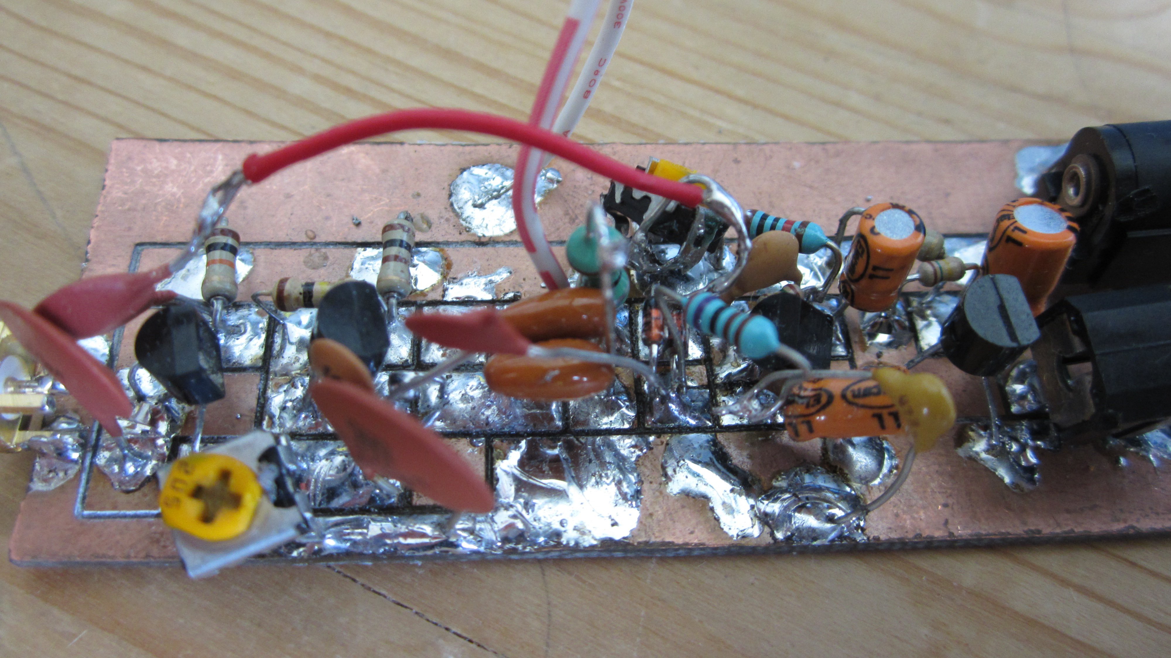
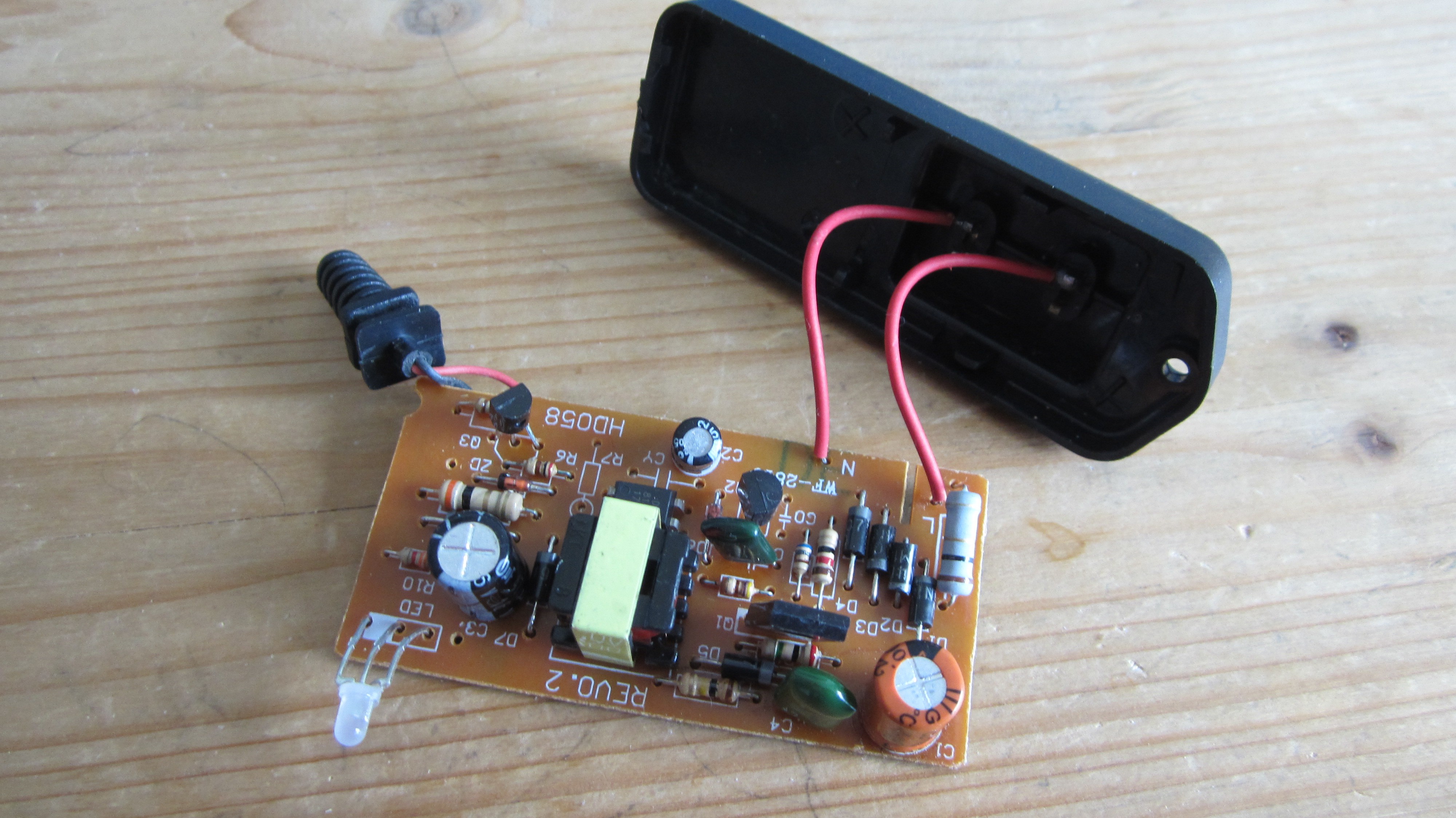
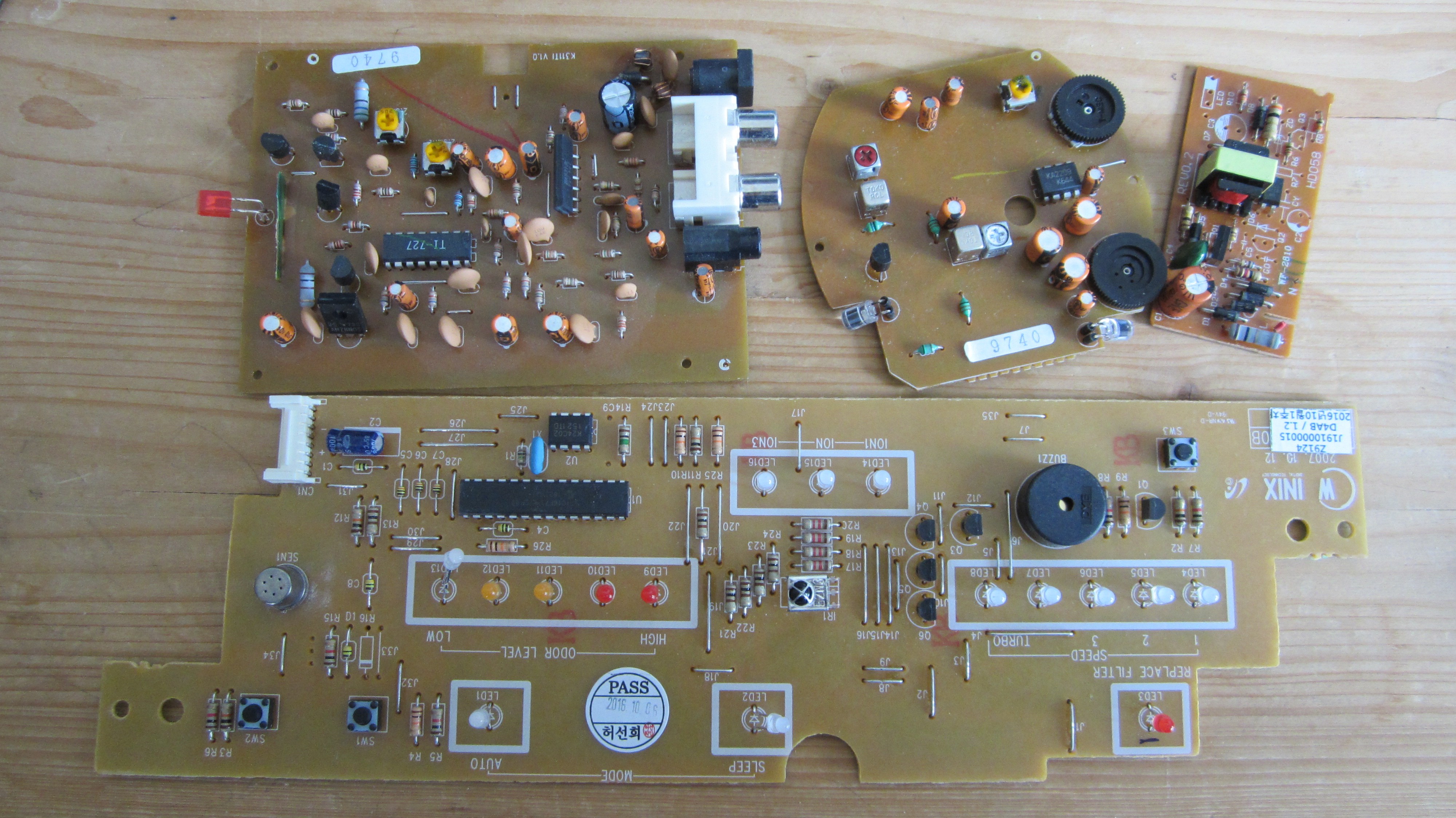
05/24/2020 at 11:41 • 0 commentsWe have a working prototype! Almost all the components are scavanged from PCBs that were meant for a completely different purpose, it makes me happy that they get a new purpose in this radio receiver.
Initially I built the VFO with salvaged varactor diodes as varicaps. It worked well and I could cover the 20m amateur band completely. I had two 1n4004 diodes back to back, and fed the control voltage at the cathode interconnection. Then I remembered that some years ago I had made this receiver topology with a ceramic resonator and I really didn't want to make this build about fighting VFO drift (which there certainly was). I'm trying to keep the components to a minimum and a trade off is that the VFO doesn't have a buffer stage. No problem though, super VXO to the rescue. Two 3.58 MHz ceramic resonators in parallel promises to cover the whole 40m amateur band, currently that's what I can see on the scope, I haven't tried this in the wild yet.
The diode mixer RF termination pot also serves as volume control. The amplification is pretty good for using two NPN transistors. In fact all the transistors are from the scrap boards, I had to twist the BJT legs around to match them to my board pads, this wasn't a problem. For anyone building this receiver from scrap, most of the component values are not critical and I'm sure mine aren't a perfect fit. For the transistors you should check online which ones are best for HF gain (RF amp and LO) and the others can be used in the audio amplification.
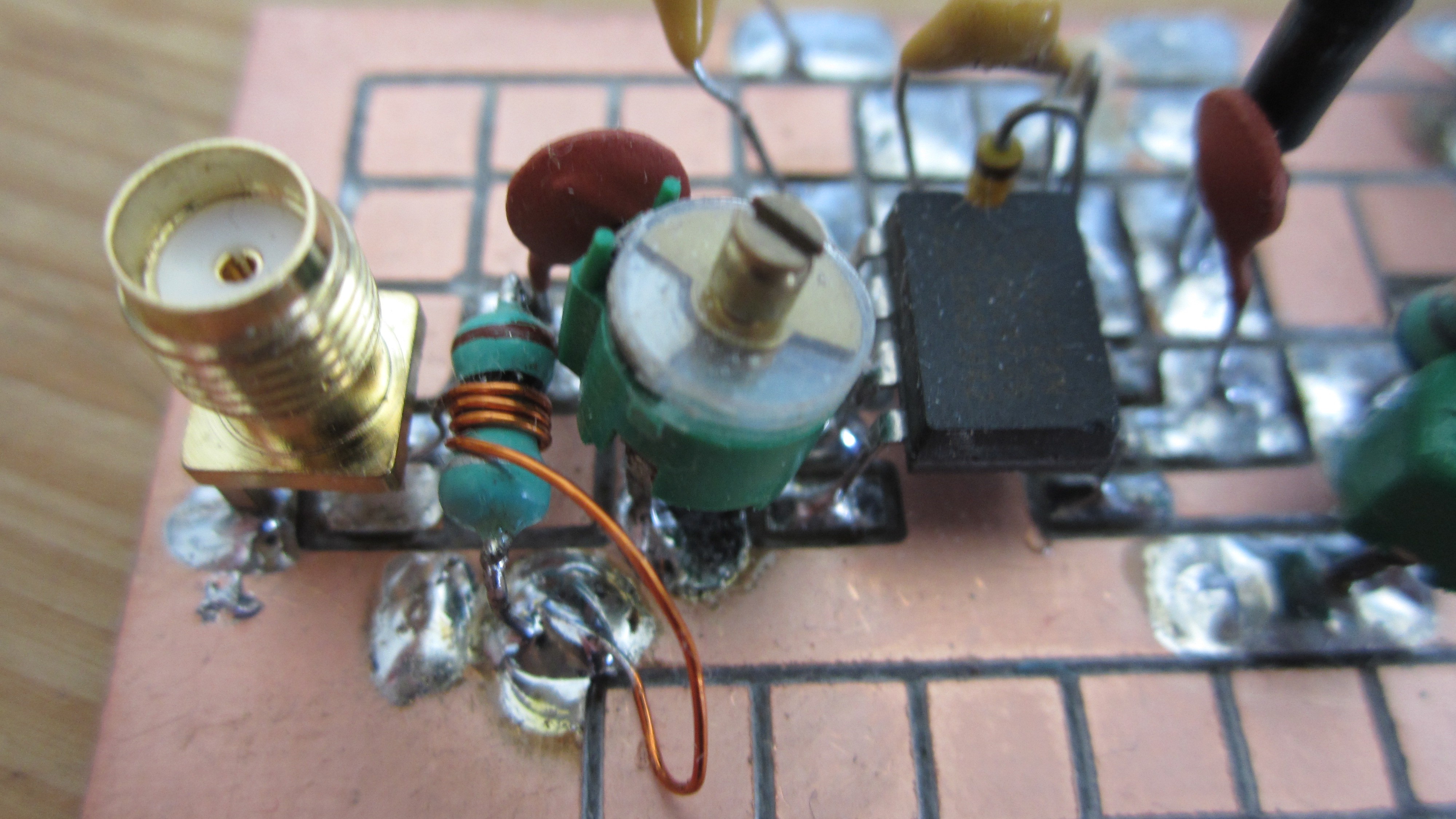
I tested the receivers 'ears' with a si5351 signal and it feel very promising, next I need to find a scrap enclosure and take the Polymorph receiver for a walk. I will probably add some form of a simple RF bandpass filter, a good chance to show some impedance matching tricks. Below is a sa612 superhet transceiver prototype.
-
Board Design
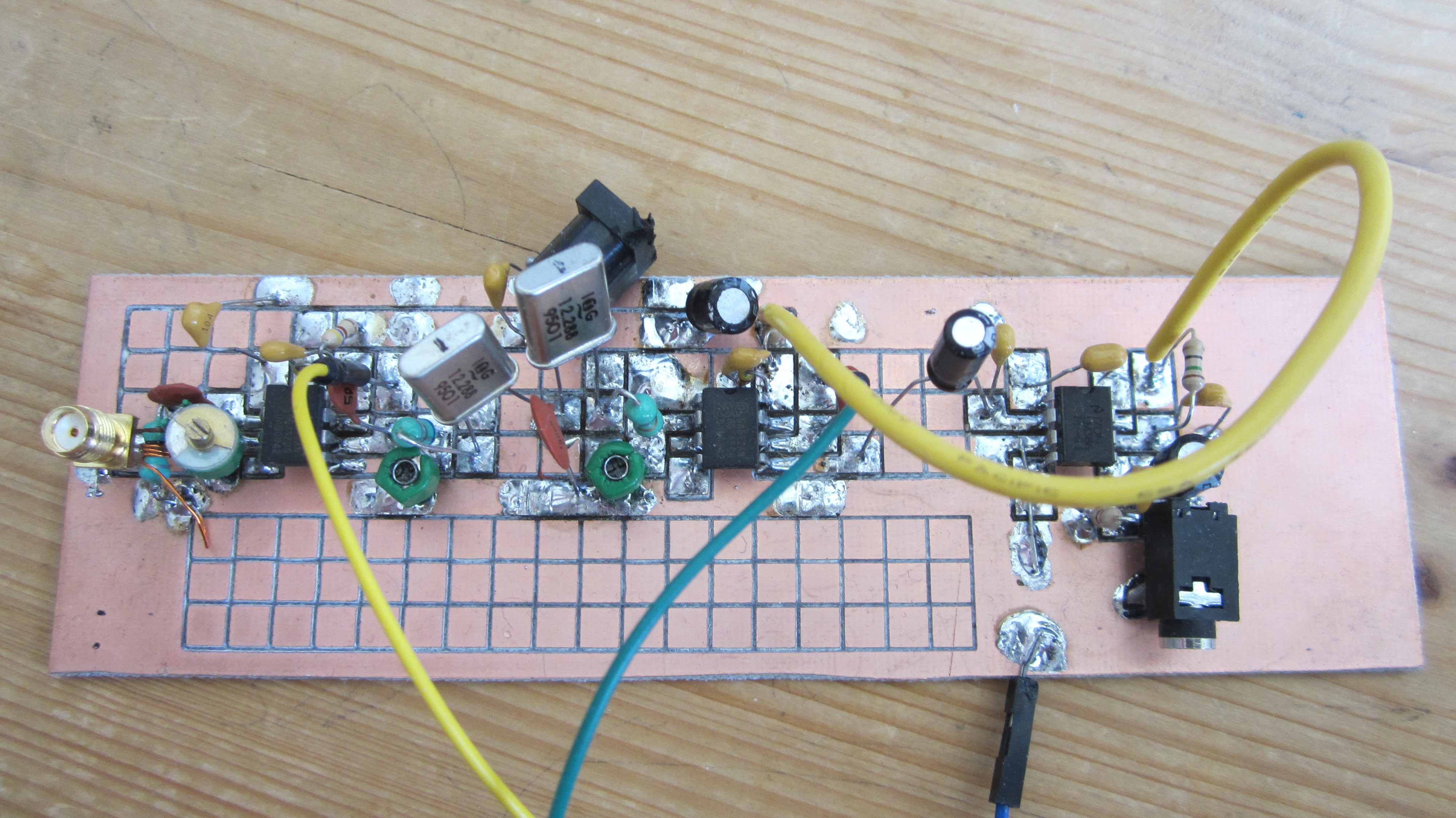
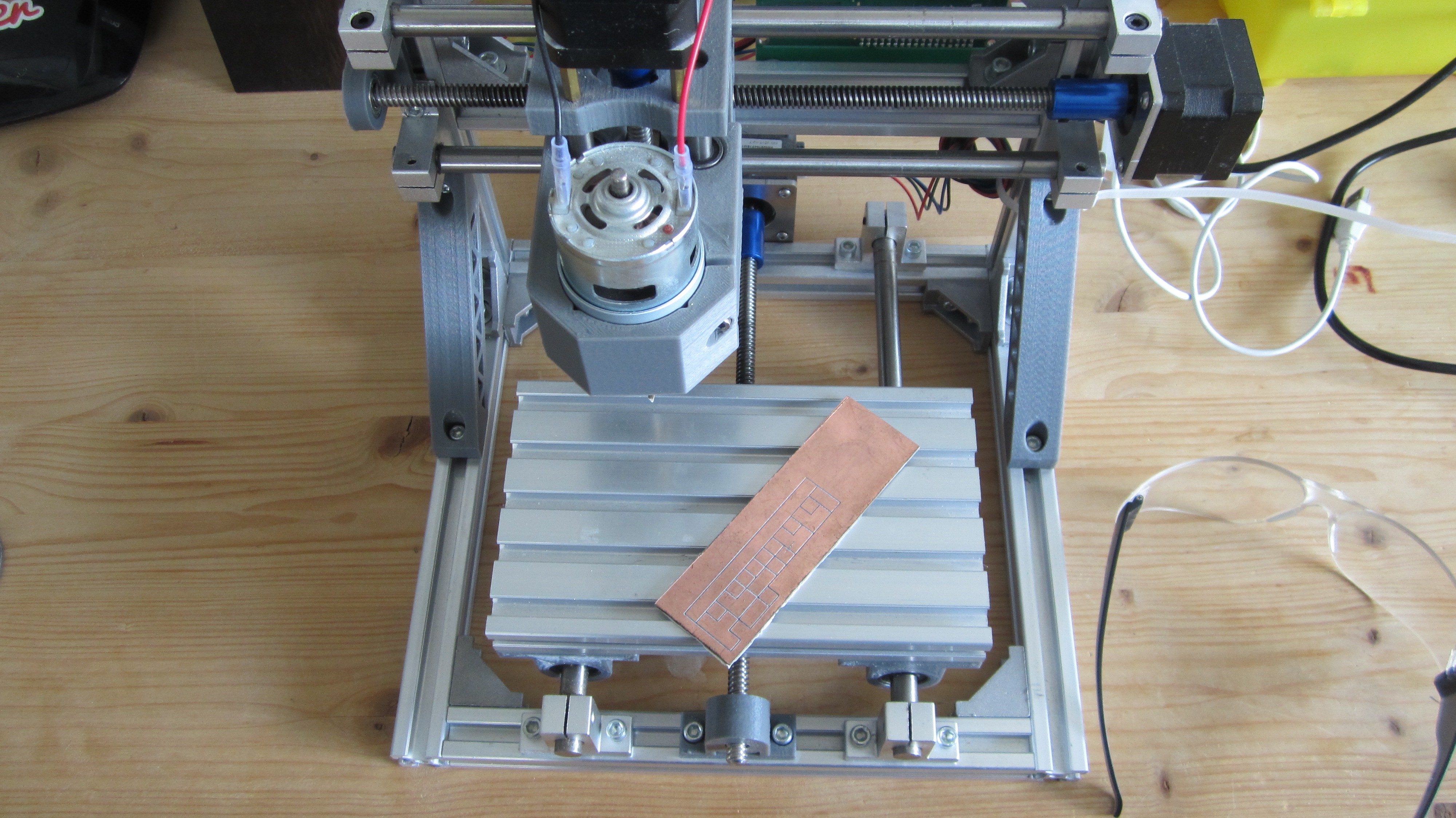
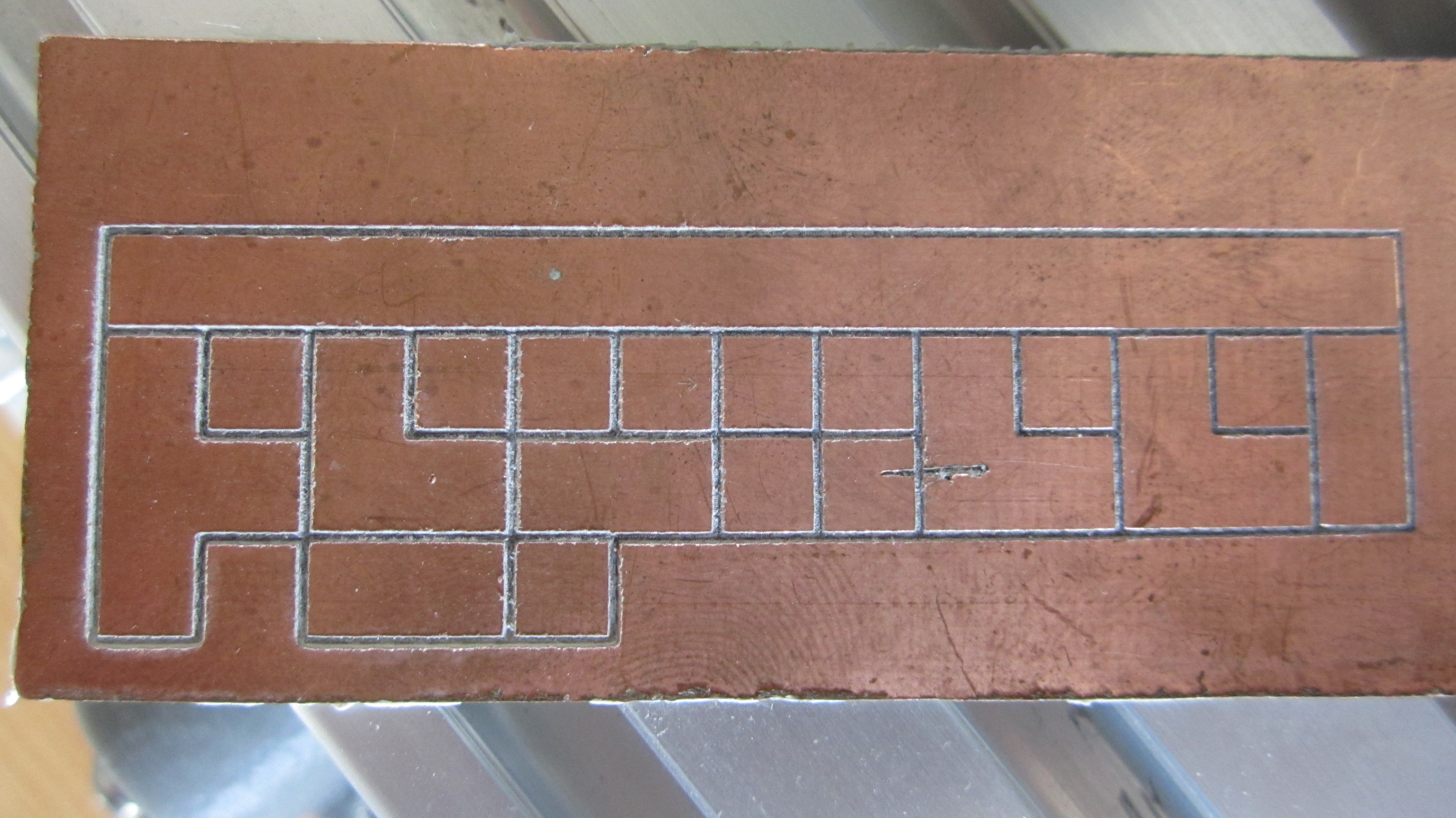
05/08/2020 at 17:24 • 0 commentsSince I ordered my small kit CNC machine after I saw a blog post about it on Hackaday I've been fine tuning my rapid prototyping techniques. Above is the machined PolyMorph receiver pcb board. Currently I'm experimenting with the muppet style construction with my own twist; I keep everything very close and squarey.
I start the design process on Inkscape. In the document properties I set the grid size to 2.54 by 2.54 mm, major lines every 4. I then make adjacent squares of 5.08 mm depending on what I want to lay on the board. For example on the far left of the pcb image there is a tetris T shape, that's for the base of a common emitter RF amp. The top long strip is the vcc.
Next, I open up JSCut in my browser, load the svg from Inkscape and generate some Gcode. Then it's time for Chilipeppr, still on the browser. Finally, voila a machined pcb!
I've made quite a lot of boards this way. I love the speed of it once you get the knack of it. I think of a design and in 30 minutes I'm soldering components onto the board. One big advantage of this unorthodox method is that I can mostly fix any mistakes by extending the through hole components to where they need to go and split squares by hand, or a blade... my hands are not that sharp :D
In the next update I will post some pictures of some scavenged components on the board and some component trickery. There'll some tips on how to get some serious 'pff' out of standard varactor diodes as varicaps and a relief for those of you who either don't have ferrite toroids on hand or would like to know another method of notorious e-imp-matching-dance courtship practice.
-
A New Build
05/01/2020 at 11:09 • 0 commentsBeginning of 2020 I decided that I'd start building electronics projects out of what I have and put ordering new parts on hold. It feels like now it's time to build the PolyMorph Receiver on a new board. I'll try to recycle as many parts as I can from old electronics that I have lying around. I'll test different configurations and tricks to make the most out of the sub-harmonic mixer. Nevertheless, the idea is still the same, anyone should be able to build this. I'll also document my construction methods.
-
Colpitts Oscillator
01/09/2019 at 13:58 • 0 commentsI added some pictures of just the colpitts oscillator of the circuit. In the picture the BJT is 2n3904 and it's collector resistor is 470 ohm, base to voltage supply rail is 150k ohm. 100 ohm and 100k ohm will work respectively. The supply voltage is 5v.
-
OH6UAV
12/23/2018 at 18:25 • 0 commentsOne of the goals of this project has been accomplished, I'm now a licensed radio amateur! I got my license over a year ago and have a lot of fun on the HF bands. My current DX record is a contact to Suriname from Finland, ~9000 km on the 15m band with an 13.5 m end fed antenna a 9:1 unun and only 10 watts. My rig is an 'old' Kenwood TS-50, but it works like a charm. Timing is key on the air and so is chasing your dreams!
-
RF Amp
05/22/2015 at 08:05 • 0 commentsAdded another common emitter amp, this time for incoming RF.
The performance boost is immense, small signals are much easier to hear and large ones boom (CW and SSB).
Unwanted outward RF leakage seems to have been greatly reduced.
I use an atennuator pot to better hear stations, diminish AM breakthrough and generally control audio volume.
Updated schematic and pictures coming soon!
-
Log
03/10/2015 at 15:41 • 0 comments10.03.2015
Uploaded modified schematic. There was a 100k resistor missing on the vfo transistors base. Without it the the vfo doesn't oscillate. The 1n4148 diodes seem to like a 1-1.2 peak to peak oscillator voltage for optimal performance. Currently I have a 4.7uH inductor as the vfo tank and a 1.5uH antenna tuning/impedance matching inductor next neck on neck with it (this is one of the places where the magic happens). The 120p antenna capacitor should be reduced to something like 20p to avoid hum/motorboating in the audio chain. especially when you use external speakers. Keep the audio transistor emitter connection AS SHORT AS POSSIBLE to ground. I'll put a demo video on youtube.
PolyMorph Receiver
A minimalist direct conversion radio receiver. 4 general purpose transistors and a Polyakov 2 diode mixer.
 morph
morph