Carl Bugeja
-
FlexPCB Motor + Steel Stiffener Test
10/08/2021 at 06:53 • 1 comment -
Version 4
08/05/2021 at 17:36 • 0 commentsOpen Source Files - https://github.com/CarlBugeja/PCB-Motor-v4
-
PCB Motor Wheeled Robot v1
05/19/2021 at 12:42 • 0 comments -
PCB Motor v3
06/05/2020 at 16:12 • 1 comment -
How to design a PCB Motor?
04/10/2020 at 13:46 • 0 comments -
Rotor Flux PCB Motor
07/13/2019 at 17:22 • 0 commentsThis video shows my attempt in trying to design a rotor-flux brushless pcb motor prototype:
-
SPEED!
06/04/2019 at 00:59 • 0 commentsHow fast can my PCB Motor go?
-
CORE PCB Motor
01/07/2019 at 19:06 • 0 commentsCheck out this teardown of the CORE-PCBMotor!! I came across this motor a few months ago, after a few people who saw my design sent me their website's link. There's not much information on it and its also patented but this guy managed to take it apart and review it.
http://build-its-inprogress.blogspot.com/2018/12/core-outdoor-power-pcb-motor-teardown.html
I have no idea why they decided to use it for a lawn trimmer (there's much more interesting applications) but its very interesting to see how it was designed, the way the windings are connected and that it has sufficient torque to rotate a blade!
-
Smallest PCB Motor
10/31/2018 at 00:11 • 0 commentsMy SUPER tiny 6-layer PCB Motor is spinning! Here's the full video describing how I designed it:
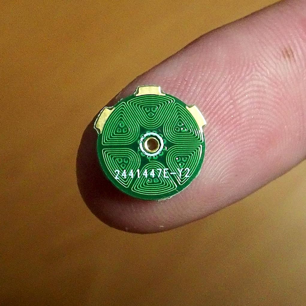
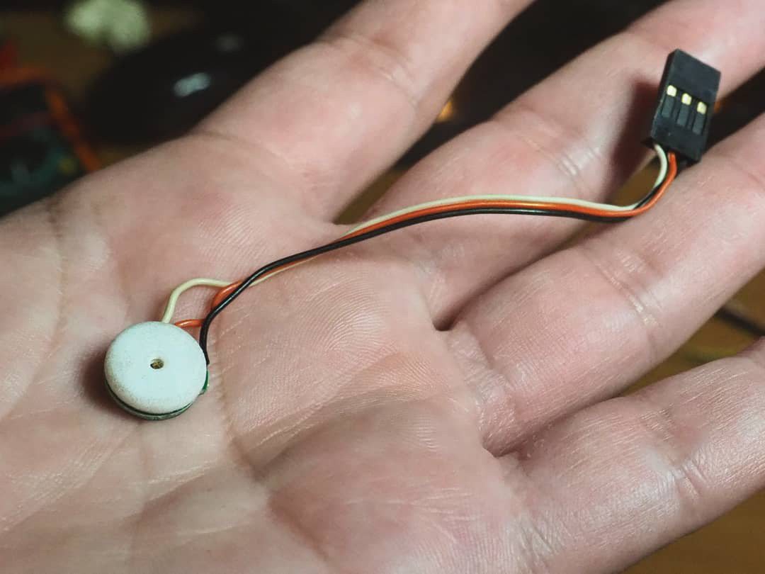
My original 4-layer PCB motor had a 16mm diameter. By adding two extra layers I was able reduce the number of turns per layer and get it to 11mm. The total height of the motor is 3.6mm and its weight is 0.5 grams.
No space is lost in this pcb! Each coils have 3 vias to connect the in-between layers. These forced a triangular shaped stator poles, which utilize the magnetic field area more efficiently.

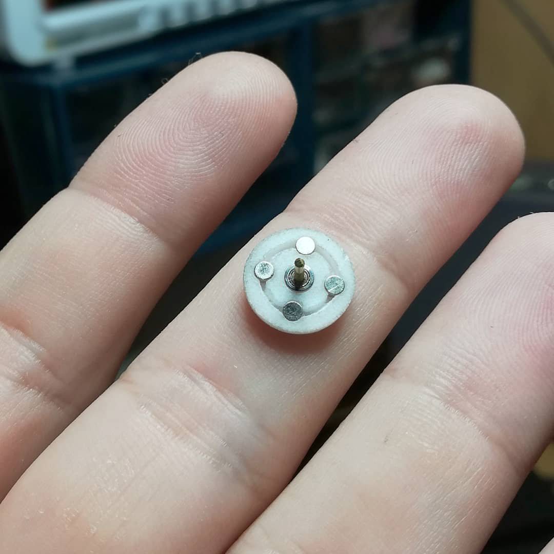
The tiny rotor design has four press-fit 2mm n52 magnets and a 3mm bearing. This new design has the shaft soldered onto the stator, so it is fixed and don't rotate with the rotor.
I had chosen to go with this design because of two things:
1. I couldn't find a bearing small enough to fit in the middle of the stator.
2.I'm not planning to use a shaft. Customized 3d-printed rotors makes much more sense.
The phase resistance of this motor was measured to be 15ohmsand its getting to 85℃ with a 4V supply, so it should be perfect for a 1s lipo. -
ESC details
10/20/2018 at 17:52 • 0 commentsThis video shows how i designed my PCB Motor's ESC and what where the challenges involved in getting my speed controller to work.
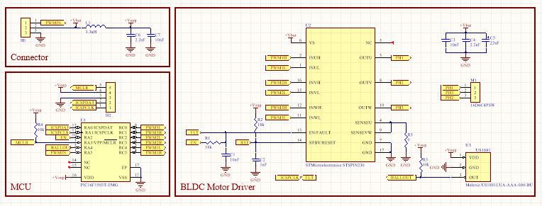
This is its schematics:
It has a PIC16F1503 as the main controller and a triple half bridge driver STSPIN230, to control the three phases of the motor. These are both powered from the same supply, to avoid having an extra power wire or on-board regulator, reducing the cost even further. I filtered the digital circuitry supply from an LC filter to attenuate any noise the motor can generate. It can operate from a 5V to 2.6V supply and draws around 220mA in total.
As i explained in my previous project logs, the back emf generated from my pcb motor was too weak to implemented a sensorless speed controller. So i decided to use a hall sensor to provide feedback to the microcontroller and then implemented a speed closed loop speed controller.
The open source gerber files and schematics for this PCB are available for download.
In the beginning of November I will be giving a demo of this project at the Hackaday Superconference so see you there!