Carl Bugeja
-
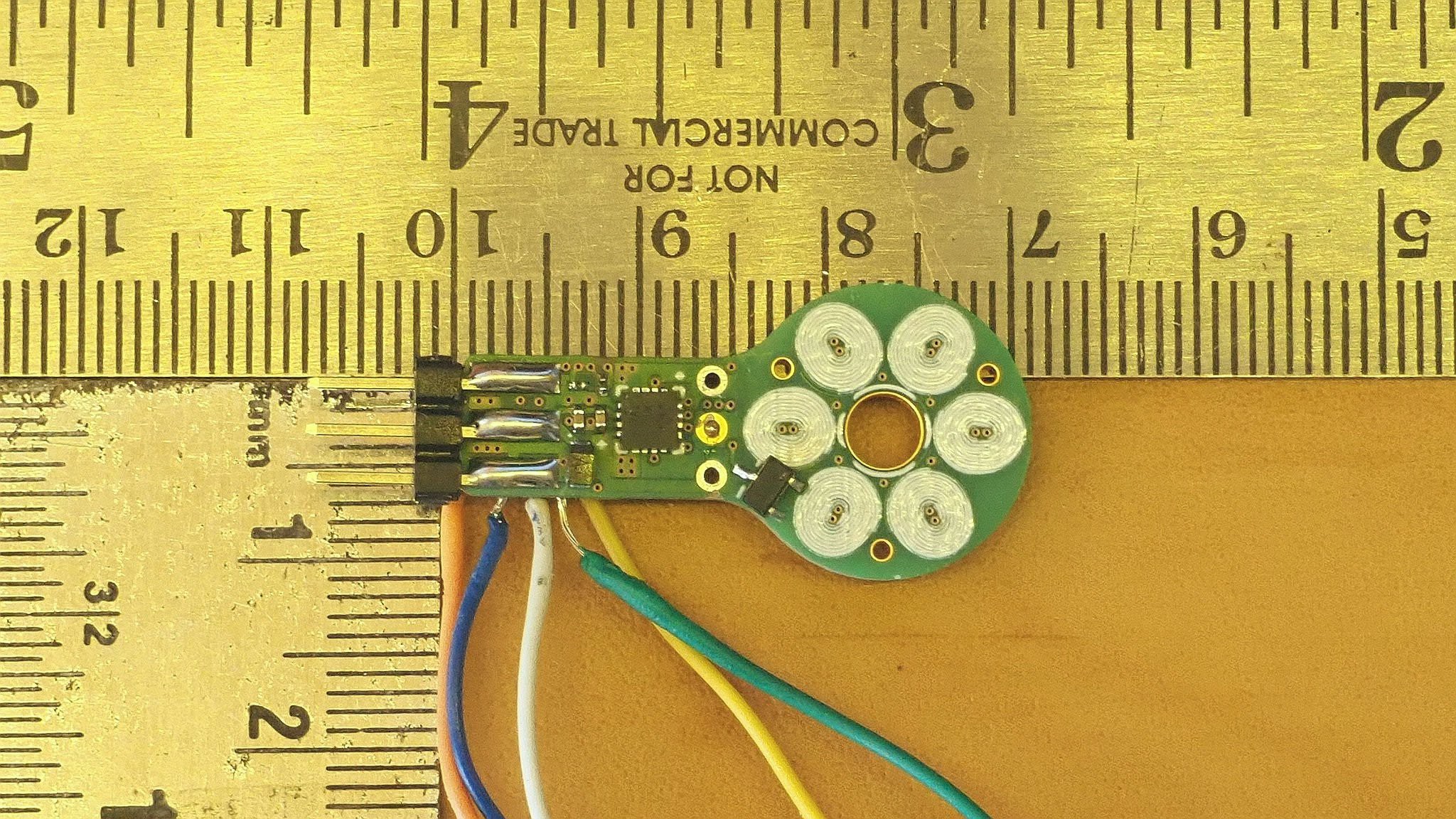
PCB Motor with integrated ESC!
10/14/2018 at 14:36 • 0 commentsI have finally finish my PCB Motor with the integrated ESC! Made this quick video showcasing it:
The PCB was hand soldered. It took me a little while to get it to work because I had some soldering flux residue on one of the motor driver chip that was acting as impedance. This was triggering the driver's on-board protection circuit. But after removing the chip and clean its pads, it was up and running.
I have managed to fit the ESC in such a small area by soldering parts on both sides of the PCB and using the smallest footprints I could find! Both the MCU and motor driver have a 3x3mm qfn package and most of the other discrete components are 0201s!
![]()
I'm currently making another video explaining how i design this driver and what were the challenges involved! So I will be releasing its schematics and gerber files in the next few days :)
-
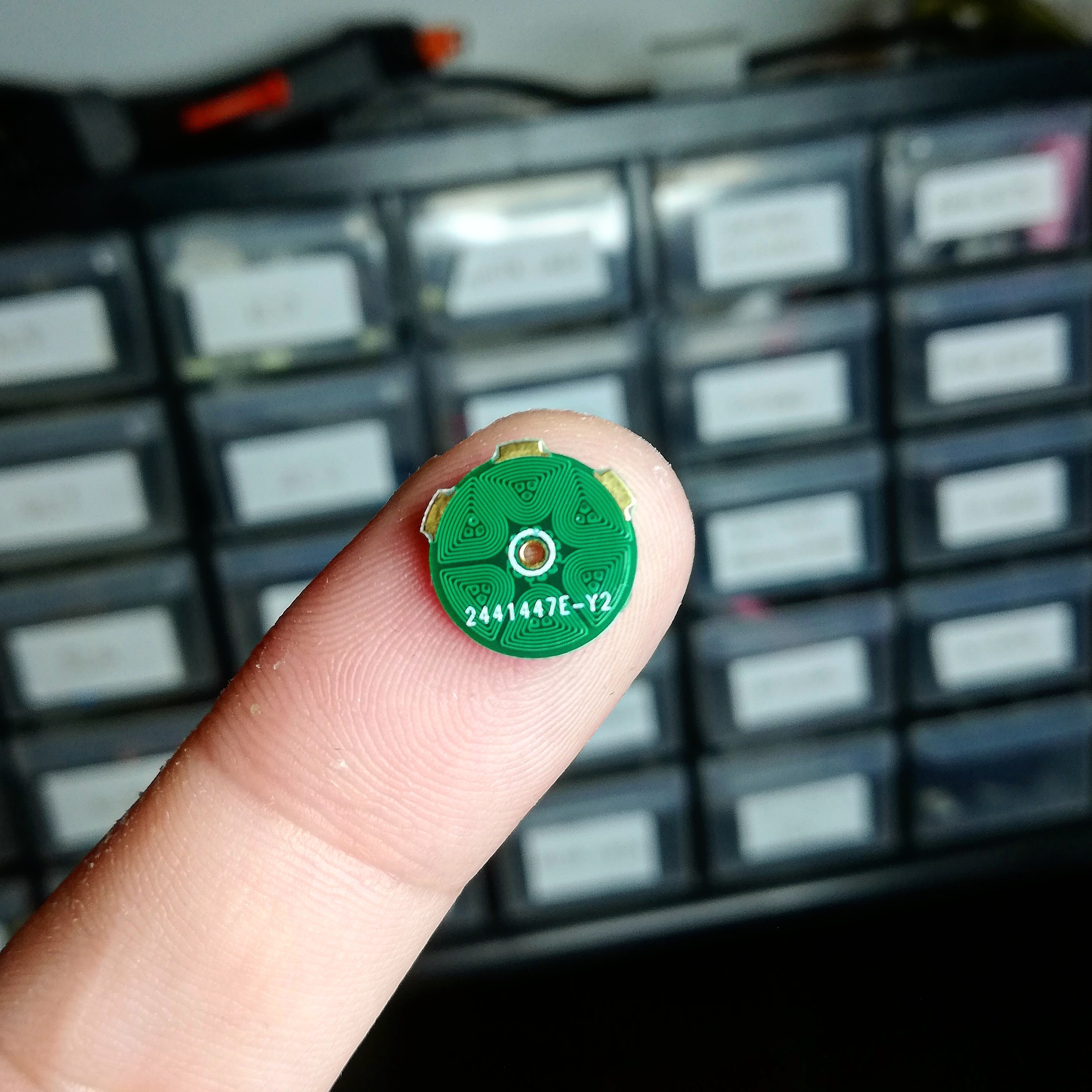
SUPER tiny 6-layer PCB Motor
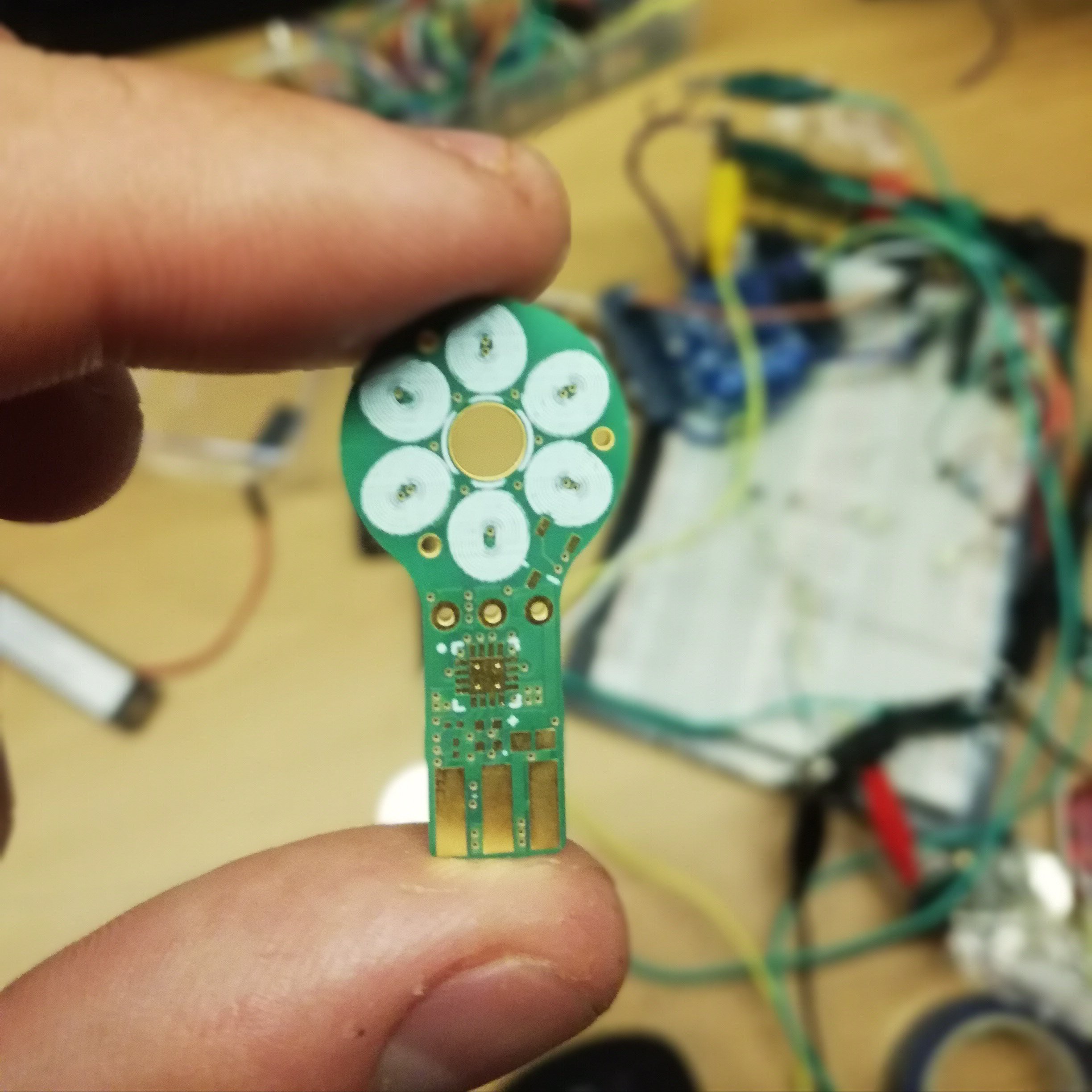
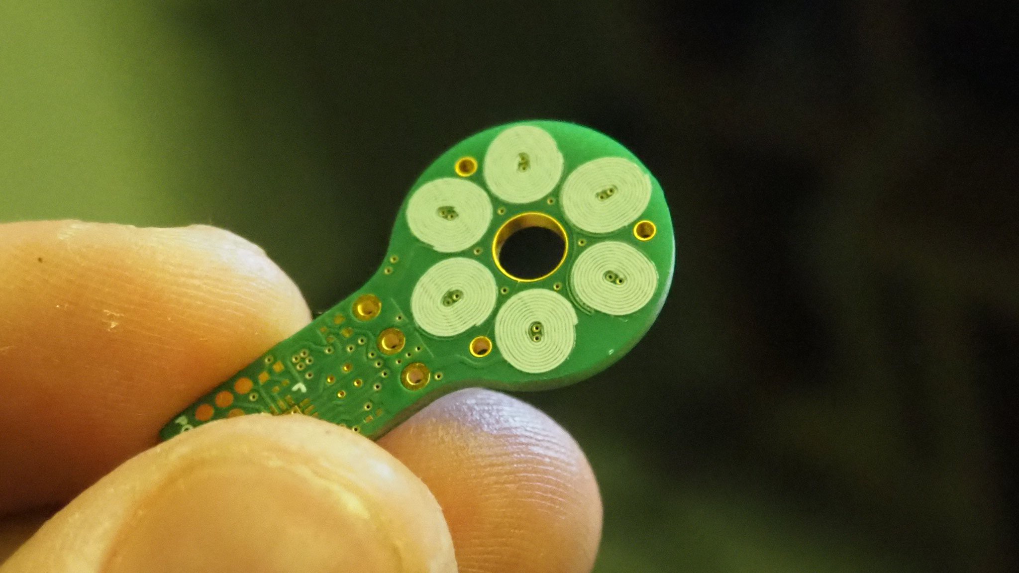
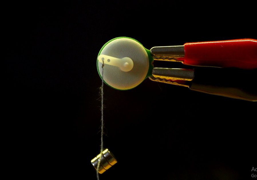
10/12/2018 at 21:22 • 1 commentToday I have received my super tiny 6-layer PCB stator measuring 11mm in diameter.
![]()
![]()
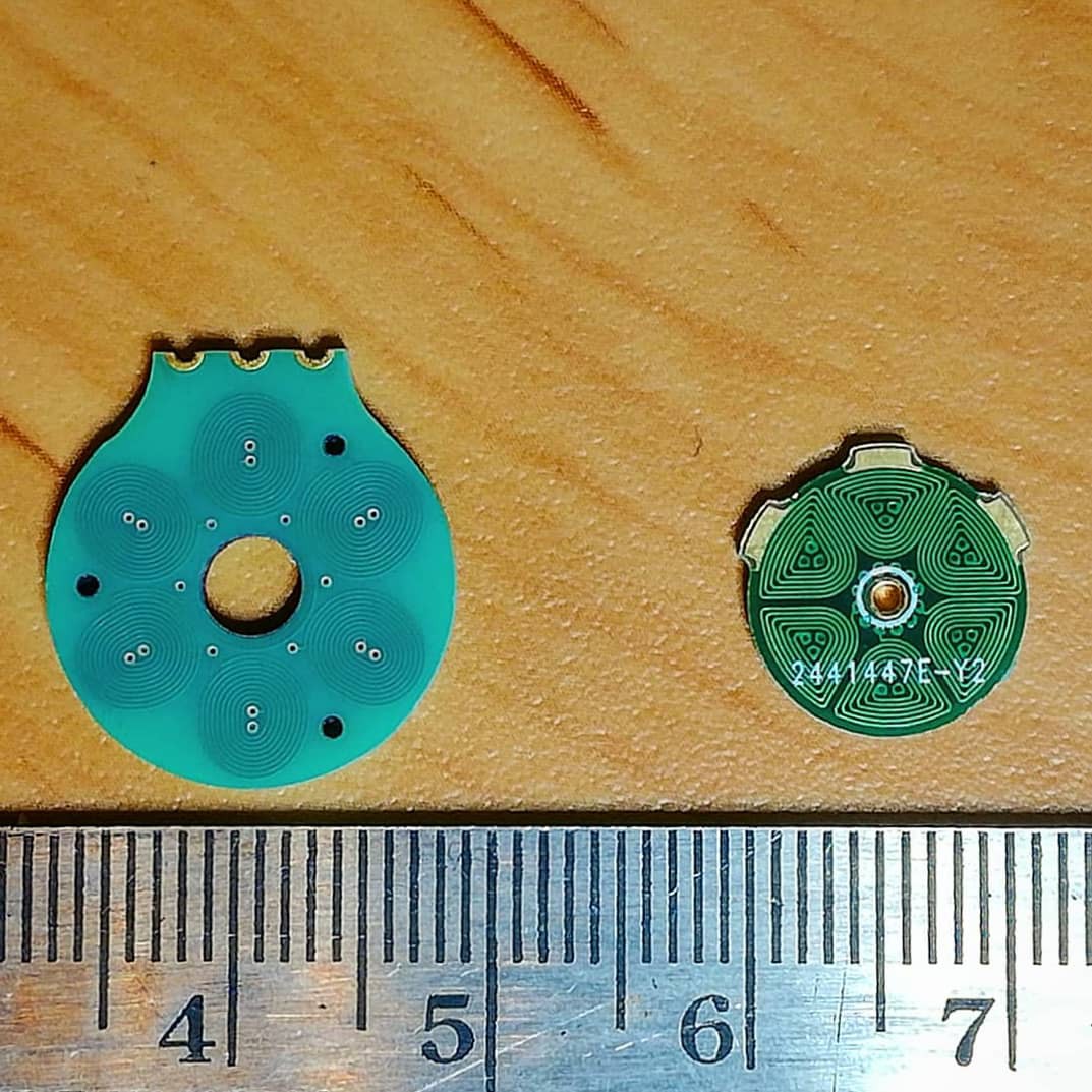
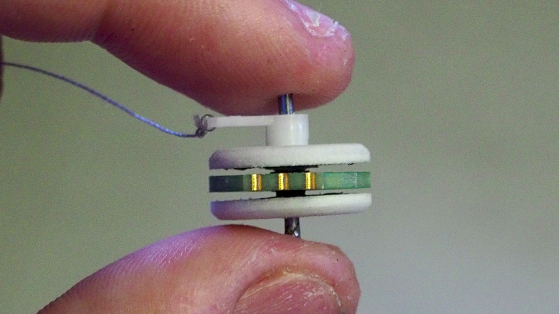
This is how it compares to my 4-layer prototype.
![]()
I'm super excited to test this thing out and see it run, but unfortunately the magnets still haven't arrived yet :/ stay tuned for more updates!
JLCPCB was cool enough to sponsor and manufacture this tiny 6-layer PCB Motor! I highly recommend them if your looking for super cheap pcb prototypes.
-
6-layers
10/02/2018 at 19:46 • 3 commentsI love designing electronics that fit in very tiny space. My 4-layer brushless PCB Motor is currently 16mm in diameter. So how can I make it smaller?
This 16mm design is already pushing the limits by having 4mils (0.1mm) track width and clearance. Using thinner pcb traces is possible, but would make its price (for prototyping) explode. My intent is to make this open source motor accessible to others, so it doesn't makes much sens to go in this direction. So I'm sticking to 4/4mil traces.
My motor has around 40 turns, so going much lower than that would make the coils too inefficient and the pcb would heat up way to much. Based on a my pcb coils tests the minimum number of turns for 4mil should be 40 turns and for 5mil it should be 60 turns, not to exceed 70°C with a constant (100% duty cycle) supply.
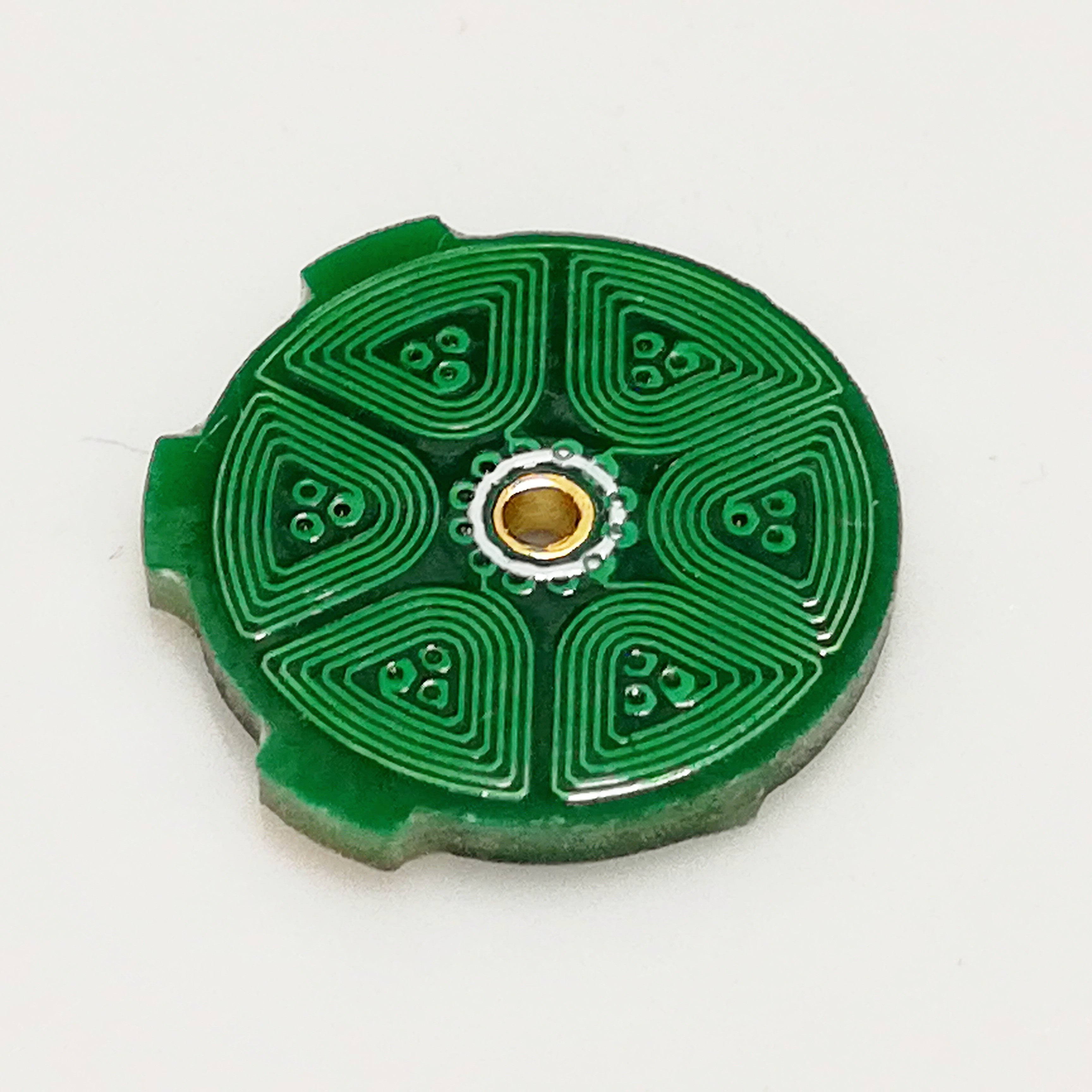
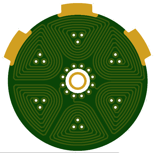
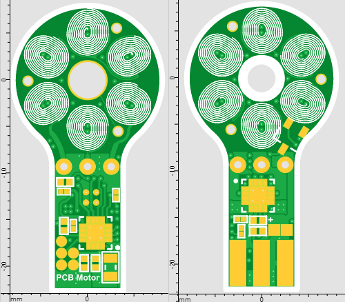
The only remaining option to try and make it smaller, is to increase the number of layers to decrease the number of turns per layer. The current design has 10 turns per layer, so for this tiny 6-layer motor I decided to go for 6 turns per layer, having a total of 36 turns. Setting a tight clearance of 4mil, the total diameter of the motor end up being 11mm.
The extra two layer, increased the number of vias in the middle of each coil to three. This naturally formed the spiral to have a triangular shape which use the area of the magnetic field more efficiently.
Another natural advantage of using a 6-layer pcb, is that the thickness between each layer is much smaller which increases the magnetic field strength.
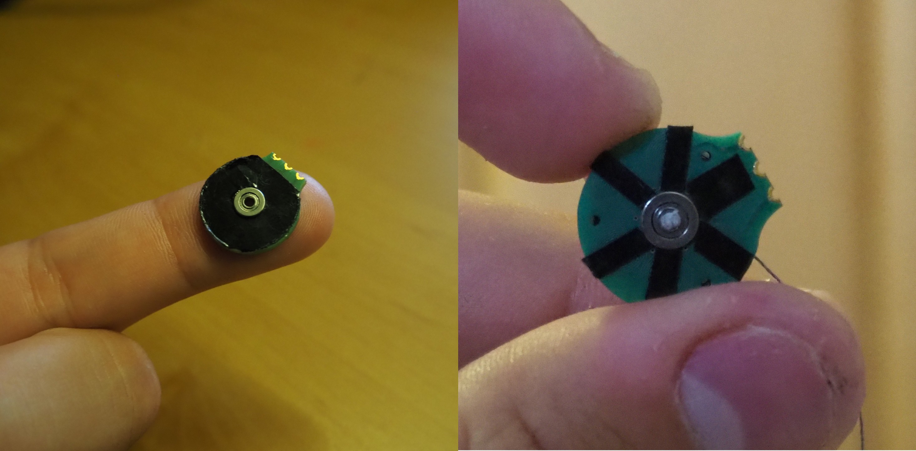
For this design I had to make some changes on the rotor, because I couldn't find a bearing small enough to fit at the center of the pcb (smallest bearing available is 2mm). So what i decided to do is extended a stationary-shaft from the pcb, and connect the bearing on the rotor. I'm still designing the 3d-printed part, so I will post more info on that soon.
I have just ordered this 6-layer pcb motor from JLCPCB which were kind enough to sponsor this design.
We'll see how it goes!
![]()
-
Project Update
10/02/2018 at 17:07 • 0 commentsHere's a quick update video on my brushless PCB Motor project, with a list of things I was working on and what I plan to do next.
-
IEEE Spectrum - “The Printable Motor.”
08/29/2018 at 18:09 • 0 commentsMy PCB Motor got featured on IEEE Spectrum! Check out their article bellow :)
https://spectrum.ieee.org/geek-life/hands-on/how-to-print-an-electric-motor
It will also appear in the September print issue as “The Printable Motor.”
-
New PCB Soldering
08/22/2018 at 22:05 • 0 commentsSoldering of the new pcb is done! I still have to test all the components though
![]()
![]()
-
New PCBs
08/09/2018 at 20:06 • 0 commentsThe new PCBs have arrived! The rest of the components should be delivered by next week
![]()
The silkscreen on the coil traces looks a little crappy but its my fault for not checking the manufacturer's print resolution.
![]()
-
PCB Motors HackChat
08/09/2018 at 00:19 • 0 commentsNext Friday there's going to be a HackChat on my PCB Motor! Join the event to ask me any questions on the project!
-
New PCB Motor with Driver
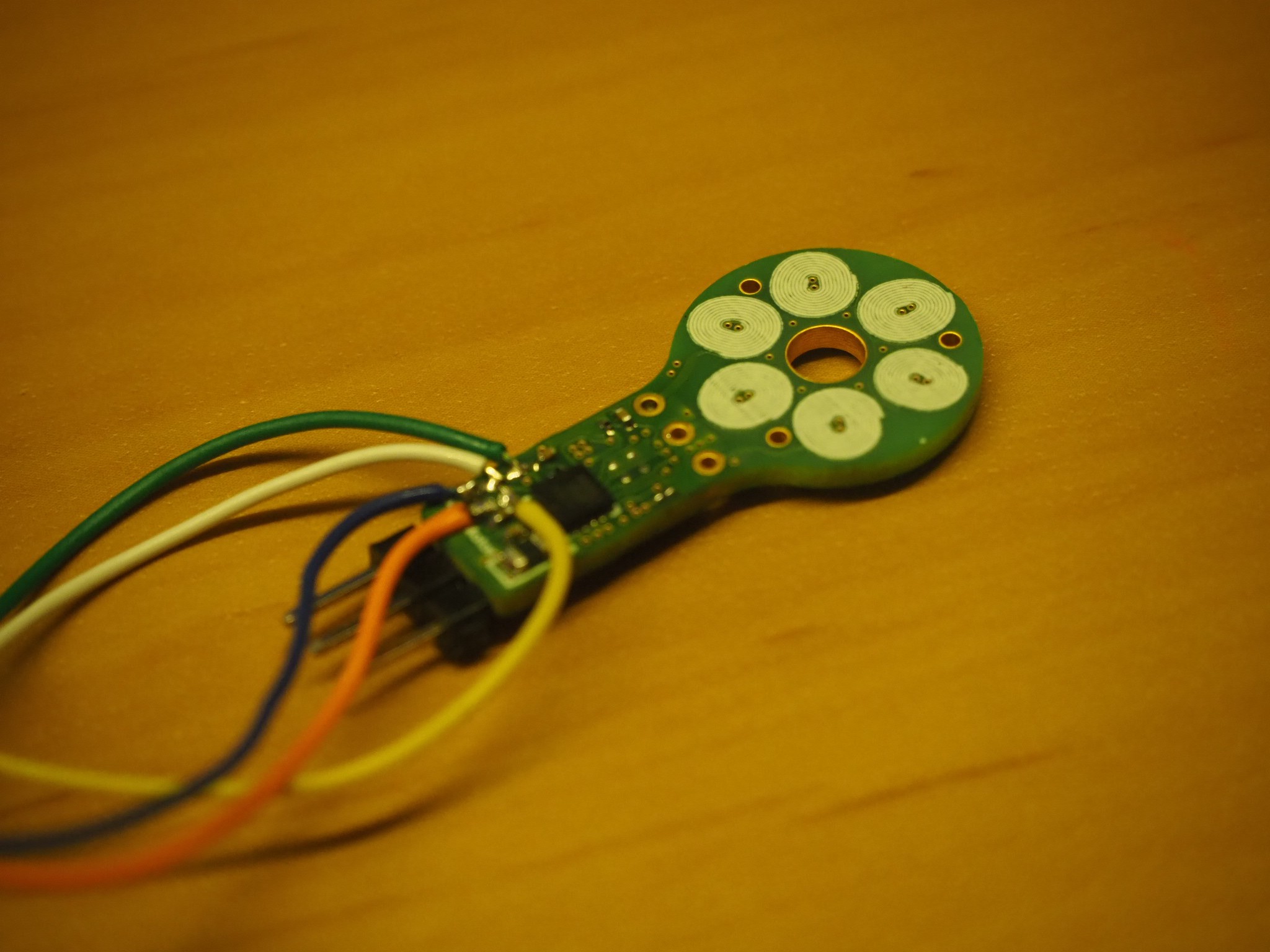
07/12/2018 at 23:24 • 1 commentI finally ordered a new PCB motor with an integrated ESC. I have managed to package the circuit in a very small space, 30x16mm including the stator. For now I have ordered the same star winding configuration that i've used in the first prototype. I'll be ordering more configurations soon.
![]()
The circuit basically consists from:
Hall Sensor (US1881) to detect the magnets inside the rotor.
- MCU (PIC16F1503) - I have shifted from the DSPIC33EP128 to the PIC16F1503. This MCU has less computational power (not much is required since I am no longer considering sensorless control) but is packaged in 3x3mm chip and is around $2 cheaper
- 3-Phase Motor Driver (STSPIN230) - which is rated at 1.3Arms, and has several types of fault protection build-in.
- A filtering circuit to supply the micro.
I will upload all the source code and gerber files once the PCB arrives and verify its functionality. Keep tuned!
-
Static Torque
06/19/2018 at 23:49 • 1 commentSo torque is the biggest weakness of my tiny PCB motor. This was measured it to be 0.9gcm.
![]()
But it is something that can be improved. These are three ways how I tried to improve it:
- Double Rotor - Some people in the comments suggested to try and use a double rotor. This will increase the magnetic field produced by the neodymium magnets and therefore will also increase the motor's torque. But in practice this was not the case and it barely had any effect. The measured torque was 0.9gcm (the same as with one rotor).
![]()
- Ferrite Sheet - This was used to act as a reflector for the magnetic field and increase its strength. Two different shaped cores were tested. The uncut one gave a higher torque value and has increased it from 0.9gcm to 1.5gcm. The only down side of this is that It has also increased the pcb's temperature from 70°C to 90°C due to eddy current losses.
![]()
- Delta configuration - Other simple way to increase the torque is by changing the configuration to a delta winding. This way the coils will be powered with a higher voltage, so it will also increases the torque and temperature (hopefully not by much). This approach was not tested yet.
Check out the full tested video: